Many cars have shiny VVT badges. They can be found even more often on engine covers. “What are these letters?” – the question sometimes confuses sales consultants and even service technicians. At best, you will hear something obscure about the gas distribution mechanism. Your request to clarify: what advantages and advantages these “three cheerful letters” provide – often remains “without comment”.
But the variable valve timing system (VVT [English Variable Valve Timing] is one of its trade names) or “phase shifter” will soon celebrate the 100th anniversary of its appearance on internal combustion engines. However, for too long such systems were used exclusively in motorsports and racing, and when they appeared on “ordinary” cars, they did not become an object of desire, such as, for example, turbocharging or “16 valves,” while playing a primary role in the perfection of engines.
In this article we will restore justice and tell you what VVT, CVVT, VANOS, MIVEC, and similar names are, which essentially refer to the same system, which is very important and useful.
Tools for setting valve timing
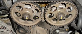
In order for the engine to operate without interruption, it is important to set the timing timing correctly and install the camshafts in the desired position relative to the crankshaft. On all engines, the shafts are set according to marks, and a lot depends on the accuracy of the installation
If the shafts are not aligned correctly, various problems arise:
- the engine is unstable at idle;
- The internal combustion engine does not develop power;
- There are shots in the muffler and popping noises in the intake manifold.
If the marks are wrong by a few teeth, it is possible that the valves may bend and the engine will not start.
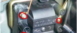
On some models of power units, special devices have been developed for setting valve timing. In particular, for engines of the ZMZ-406/406/409 family there is a special template with which the camshaft position angles are measured. The template can be used to check the existing angles, and if they are incorrect, the shafts should be reinstalled. The device for 406 motors is a set consisting of three elements:
- two protractors (for the right and left shaft, they are different);
- protractor
When the crankshaft is set at TDC of the 1st cylinder, the camshaft cams should protrude above the upper plane of the cylinder head at an angle of 19-20º with an error of ± 2.4°, and the intake cam should be slightly higher than the exhaust camshaft cam.
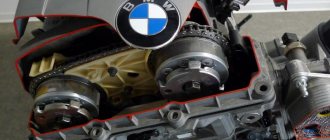
There are also special devices for installing camshafts on BMW engines of the M56/ M54/ M52 models. The kit for installing the valve timing of the internal combustion engine of the BVM includes:
- torque wrench with extension;
- adjustment plate for double VANOS system;
- pins for fixing the flywheel;
- sleeve with spindle for tensioning the primary chain;
- a device for tensioning the secondary chain, as well as for blocking the tensioner plunger;
- camshaft retainer.
Timing belt diagnostics
Window lifter mechanism for VAZ 2107
The gas distribution mechanism has 2 inherent problems - loose connection of the valves to the sockets and the inability to fully open the valves.
A loose connection of the valves to the sockets is detected by the following indicators: popping noises that sometimes occur in the intake or exhaust pipes, a decrease in engine power. Factors that cause leaky valve closure may include:
- the appearance of carbon deposits on the surface of valves and seats;
- formation of cavities on working chamfers and curvature of the valve head;
- faulty valve springs.
Incomplete opening of the valves is accompanied by a knocking sound in the engine and a decrease in its power. This breakdown occurs as a result of a significant gap between the valve stem and the toe of the rocker arm. Typical timing failures include wear of camshaft gears, pushers, valve guides, camshaft displacement and wear of bushings and rocker arm axles.
Practice shows that the gas distribution mechanism accounts for approximately a quarter of all engine failures, and preventing these failures and restoring the timing takes 50% of the labor intensity of maintenance and repair work. To diagnose breakdowns, the following parameters are used:
- determine the phases of the gas distribution mechanism of the car;
- measure the thermal gap between the valve and the rocker arm;
- measure the gap between the valve and the seat.
Valve timing measurement
Such diagnostics of the engine timing belt is performed with the engine turned off using a special set of devices, including a pointer, a torque scope, a goniometer and other additional devices. In order to fix the period of opening of the intake valve on the 1st cylinder, it is necessary to rock the rocker arm around its axis, and then direct the engine crankshaft until a gap appears between the valve and the rocker arm. A goniometer for measuring the desired gap is placed directly on the crankshaft pulley.
Measuring the thermal gap between valve and rocker arm
The thermal gap is measured using a set of probes or another special device. This is a set of metal plates 100 mm long, the thickness of which must be no more than 0.5 mm. The engine crankshaft is turned up to the upper limit point, during the compression stroke of the cylinder selected for control. Directly thanks to probes of different thicknesses, alternately inserted into the formed hole, the gap is measured.
Determining the gap between valve and seat
It can be estimated by the volume of air that will escape through the seal of the closed valves. This procedure goes well with cleaning the injectors. When they have already been removed, remove the rocker arm rollers and cover all the valves. Then compressed air is supplied to the combustion chamber under high pressure. Alternately, a device is placed on any of the controlled valves that allows you to measure air flow. If the air loss exceeds the permitted limit, the gas distribution mechanism is repaired.
Achieved results[edit | edit code]
Late closing of intake valves
(eng. late intake valve closing, LIVC). The first implementations of variable valve timing were systems that allowed the valve to be left open longer than in an engine not equipped with such a system. The result was the effect of pushing air out of the cylinder and into the intake manifold during the compression cycle. The air displaced from the cylinder increases the pressure in the intake manifold, as a result of which the next time the intake valve opens, air will be supplied to the cylinder at higher pressure. As a result of the introduction of late closing of exhaust valves, a reduction in losses in the intake tract of up to 40% is achieved, as well as a reduction in nitrogen oxide (NOx) emissions by up to 24%. Maximum engine torque is reduced by approximately 1% and hydrocarbon emissions remain unchanged.
Early closing of intake valves
(eng. early intake valve closing, EIVC). Another way to reduce losses in the intake tract, applicable at low engine speeds, is to create a high vacuum in the intake manifold using early closing of the intake valves. To achieve this, the intake valves must close during the intake cycle. At low load, the engine's need for the fuel-air mixture is small, but the requirements for filling the cylinders with it are quite high, which can be achieved by introducing early closing of the intake valves. Studies have shown that on engines with early closing of the intake valves, there is a reduction in losses in the intake tract by up to 40%, as well as an increase in efficiency by up to 7%. There is also a reduction in nitrogen oxide emissions of up to 24% in part-load modes. A possible negative side of introducing early closing of the intake valves is a significant decrease in the temperature in the combustion chamber, which can cause an increase in hydrocarbon emissions.
Early opening of intake valves
(eng. early intake valve opening). Opening the intake valves earlier is a way to significantly reduce emissions. A traditional engine uses a process known as valve overlap to control cylinder temperatures. When the intake valves open early, part of the exhaust gases flowing through the intake valve enters the intake manifold, where it is quickly cooled. Upon intake, the inert exhaust gases will largely fill the cylinder, resulting in a reduction in cylinder temperature and a reduction in nitrogen oxide emissions. Also, early opening of the intake valves improves volumetric efficiency since the volume of exhaust gases emitted is reduced during the exhaust cycle.
Early and late closing of exhaust valves
(eng. early/late exhaust valve closing). The introduction of these systems makes it possible to achieve a reduction in toxicity. In a traditional engine, during the exhaust cycle, the movement of the piston pushes the exhaust gases into the exhaust manifold and then into the exhaust system. By early and late closing of the exhaust valves it is possible to control the volume of exhaust gases remaining in the cylinder. By leaving the valve open longer than usual, it is more completely purified from exhaust gases and the cylinder is filled with a larger volume of fresh fuel-air mixture. When the exhaust valves close early, more exhaust gases remain in the cylinder, resulting in increased efficiency. The system allows the engine to maintain efficiency in all operating modes.
Why is valve actuation delayed and advanced?
To improve the filling of the cylinders, as well as to ensure more intensive cleaning of exhaust gases, the valves operate not at the moment the piston reaches the dead points, but with a slight advance or delay. Thus, the intake valve opens until the piston passes TDC (from 5° to 30°). This allows for more intensive injection of fresh charge into the combustion chamber. In turn, the closing of the intake valve occurs with a delay (after the piston has reached bottom dead center), which allows the cylinder to continue filling with fuel due to inertial forces, the so-called inertial boost.
The exhaust valve also opens early (from 40° to 80°) until the piston reaches BDC, which allows the majority of the exhaust gases to escape under its own pressure. Closing of the exhaust valve, on the contrary, occurs with a delay (after the piston passes the top dead center), which allows inertial forces to continue removing exhaust gases from the cylinder cavity and makes its cleaning more efficient.
The stage of engine operation in which both valves are open simultaneously is called valve overlap. As a rule, the amount of overlap is about 10°. Moreover, since the overlap duration is very short and the valve opening is insignificant, no leakage occurs
This is a fairly favorable stage for filling and cleaning the cylinders, which is especially important at high speeds
At the beginning of the intake valve opening, the current pressure level in the combustion chamber is higher than atmospheric pressure. As a result, the exhaust gases move very quickly towards the exhaust valve. When the engine switches to the intake stroke, a high vacuum will be established in the chamber, the exhaust valve will close completely, and the intake valve will open to a cross-sectional area sufficient for intensive filling of the cylinder.
Description
Valves in internal combustion engines are used to control the flow of gases flowing into and out of the combustion chamber. The moment at which the valve state changes (opening or closing), the duration of stay in one state and the lifting height of these valves have a high impact on engine efficiency. Without installing a variable valve timing system or a system for changing valve lift, the moment at which the state of these valves changes will be independent of the speed and operating conditions of the engine, which assumes an average setting of such parameters. Variable valve timing eliminates this limitation, allowing improved efficiency throughout the engine's operating range.
In piston engines, the valves are usually actuated by the camshaft. The fists open ( raise
) valve for a certain period of time (
duration
) during each intake and exhaust cycle.
timing
of the valves is important and depends on the position of the crankshaft. The camshaft is driven by the crankshaft via a belt, chain or gear.
To operate at high speeds, the engine requires a large volume of air. However, in this case, the intake valves may close early before the required amount of air enters the combustion chamber, reducing efficiency. On the other hand, if the engine is equipped with a camshaft that allows the valves to remain open longer, such as with sport cam modifications, the engine will experience problems when operating at low speeds. Opening the intake valves before closing the exhaust valves can cause unburned fuel to escape from the engine, reducing engine efficiency and increasing emissions.
Early variable valve timing systems had a discrete (step) operating principle. For example, one setting for the opening and closing timing of the valves when the engine is running at speeds below 3500 min−1, the second setting is when the engine is running at speeds above 3500 min−1. More modern systems produce smooth (stepless) adjustment of the opening and closing timing of the valves. Such systems allow for optimal adjustment of the gas distribution mechanism for any speed and operating conditions of the engine.
One of the simplest implementations of a variable valve timing system is a phase shift system, in which the camshaft can be rotated at a certain angle forward or backward relative to the position of the crankshaft. In this case, the valves close and open earlier or later, but the valve lift height and the duration of opening and closing remain unchanged. To be able to adjust the duration in a variable valve timing system, it is necessary to introduce more complex mechanisms, including, for example, several cam profiles or oscillating cams.
3-stage VTEC-E
What color and how are the neutral, phase and ground wires designated in electrical engineering?
The 3-stage SOHC VTEC gas distribution mechanism is a combination of the SOHC VTEC and SOHC VTEC-E systems. Unlike all the systems described above, this system has not two operating modes, but three.
At the first stage, when the crankshaft rotation speed does not exceed ~2500 rpm, the rocker (rocker arm) of the first and second ones operate independently. The almost round cam of the second valve actuates the second valve through the rocker, i.e. in fact, the intake process is carried out through the first valve, while the second valve is only slightly opened to avoid the accumulation of fuel above it. The cam of the second valve runs idle. In the second stage, starting at approximately 2500 rpm, oil supplied through a passage in the camshaft presses on the timing rod, which connects the rockers of the first and second valves, ensuring that both intake valves operate synchronously according to the cam profile of the first valve. The remaining cams work idle. In the third mode, the oil still presses on the rod in a position where synchronous operation of both valves is ensured, while, starting from ~4500 rpm, oil begins to flow through the channel into the other cavity and put pressure on the pin, ensuring the transfer of valve control from a third cam with a larger profile, providing greater lift height.
In the low speed zone, the system ensures economical engine operation with a lean fuel-air mixture. In this case, only one of the intake valves is used. At medium speeds, the second valve comes into operation, but the valve timing and valve lift do not change. The engine in this case produces high torque. At high speeds, both valves are controlled by one central cam, which is responsible for extracting maximum power from the engine.
Achieved results
Late closing of intake valves
(eng. late intake valve closing, LIVC). The first implementations of variable valve timing were systems that allowed the valve to be left open longer than in an engine not equipped with such a system. The result was the effect of pushing air out of the cylinder and into the intake manifold during the compression cycle. The air displaced from the cylinder increases the pressure in the intake manifold, as a result of which the next time the intake valve opens, air will be supplied to the cylinder at higher pressure. As a result of the introduction of late closing of exhaust valves, a reduction in losses in the intake tract of up to 40% is achieved, as well as a reduction in nitrogen oxide (NOx) emissions by up to 24%. Maximum engine torque is reduced by approximately 1% and hydrocarbon emissions remain unchanged.
Early closing of intake valves
(eng. early intake valve closing, EIVC). Another way to reduce losses in the intake tract, applicable at low engine speeds, is to create a high vacuum in the intake manifold using early closing of the intake valves. To achieve this, the intake valves must close during the intake cycle. At low load, the engine's need for the fuel-air mixture is small, but the requirements for filling the cylinders with it are quite high, which can be achieved by introducing early closing of the intake valves. Studies have shown that on engines with early closing of the intake valves, there is a reduction in losses in the intake tract by up to 40%, as well as an increase in efficiency by up to 7%. There is also a reduction in nitrogen oxide emissions of up to 24% in part-load modes. A possible negative side of introducing early closing of the intake valves is a significant decrease in the temperature in the combustion chamber, which can cause an increase in hydrocarbon emissions.
Early opening of intake valves
(eng. early intake valve opening). Opening the intake valves earlier is a way to significantly reduce emissions. A traditional engine uses a process known as valve overlap to control cylinder temperatures. When the intake valves open early, part of the exhaust gases flowing through the intake valve enters the intake manifold, where it is quickly cooled. Upon intake, the inert exhaust gases will largely fill the cylinder, resulting in a reduction in cylinder temperature and a reduction in nitrogen oxide emissions. Also, early opening of the intake valves improves volumetric efficiency since the volume of exhaust gases emitted is reduced during the exhaust cycle.
Early and late closing of exhaust valves
(eng. early/late exhaust valve closing). The introduction of these systems makes it possible to achieve a reduction in toxicity. In a traditional engine, during the exhaust cycle, the movement of the piston pushes the exhaust gases into the exhaust manifold and then into the exhaust system. By early and late closing of the exhaust valves it is possible to control the volume of exhaust gases remaining in the cylinder. By leaving the valve open longer than usual, it is more completely purified from exhaust gases and the cylinder is filled with a larger volume of fresh fuel-air mixture. When the exhaust valves close early, more exhaust gases remain in the cylinder, resulting in increased efficiency. The system allows the engine to maintain efficiency in all operating modes.
Service
Since the system includes a filter, it is recommended to change it. The average replacement interval is 30 thousand kilometers. It is also possible to clean the old filter. A car enthusiast can easily cope with this procedure on his own. The main difficulty will be finding a place to install the filter itself. Most designers place it in the oil line from the pump to the solenoid valve. After dismantling and carefully cleaning the CVVT filter, it is necessary to inspect it. The main condition is the integrity of the mesh and body. It must be remembered that the filter is quite fragile.
Without a doubt, the CVVT system aims to improve in all modes of its operation. Due to the presence of a system for advancing and retarding the opening of the intake valves, the engine has better fuel efficiency and reduced emissions of harmful substances. It also allows you to lower the idle speed without reducing the stability of operation. Therefore, this system is used by all leading automakers without exception.
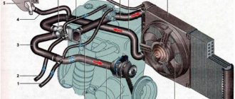
How does an internal combustion engine work?
Ignition of the air-fuel mixture in the engine cylinder leads to the release of exhaust gases and an increase in temperature. During the compression stroke, the piston moves to top dead center (TDC) compressing the air-fuel mixture or air (diesel engine).
Ignition occurs shortly before TDC. In a gasoline engine, the air-fuel mixture is ignited by a spark from the spark plug. In a diesel engine, atomized fuel is injected into hot air from compression. When the piston approaches bottom dead center (BDC), the exhaust valve timing begins. The exhaust valve opens and the piston rising to TDC squeezes the combustion products of the air-fuel mixture out of the cylinder. When the piston approaches TDC, the exhaust phase ends and the intake phase begins. The piston moves to TDC, a vacuum occurs in the cylinder, due to which air is sucked into the combustion chamber. Once TDC is reached, the intake phase ends and the compression stroke begins.
Gas distribution mechanism design
The gas distribution mechanism (GRM) consists of:
- one or two cam camshafts, each of which has its own gear;
- crankshaft gears;
- chain or belt drive.
The number of teeth on the camshaft gear is always 2 times greater than on the crankshaft gear.
Thanks to this, for two revolutions of the crankshaft, only one revolution of the camshaft occurs. This allows the cylinder head (cylinder head) valves to open and close depending on the engine stroke. The valve timing depends on the location of the camshaft cams. Therefore, on single-shaft engines, only simultaneous adjustment of the intake and exhaust phases is possible. On twin-shaft engines, separate adjustment of the intake and exhaust phases is possible. This allows you to optimize engine operation for various modes.
When the camshaft cam reaches the valve, it begins to press on it until the valve is completely open. Then the cam moves further and the spring begins to squeeze the valve, trying to close it. As soon as the pressure from the camshaft disappears, the spring completely closes the valve. The angle of rotation of the camshaft during which the intake or exhaust valves of one cylinder are open is called the valve timing.
Possible causes of valve failure
There are not many main causes of valve failure. There are two that are particularly common. So, the VVTI valve may fail due to breaks in the coil. In this case, the element will not be able to respond correctly to voltage transfers. Diagnosis of the malfunction is easily carried out by checking the resistance measurement of the sensor coil winding.
The second reason why the VVTI (Toyota) valve does not work correctly or does not work at all is jamming in the stem. The cause of such jamming may be simple dirt that has accumulated in the channel over time. It is also possible that the sealing rubber inside the valve is deformed. In this case, restoring the mechanism is very simple - just clean the dirt from there. This can be done by soaking or soaking the element in special liquids.
What do timing belt phases affect?
The engines of modern budget cars do not provide automatic adjustment of valve timing, so they are configured for medium operation. The shape of the camshaft cams of such engines is designed for maximum filling and emptying of the cylinders at rotation speeds close to maximum torque. It is usually located between 2/3 and 3/4 of maximum rpm. Therefore, such an engine “pulls poorly” at speeds below half of the maximum.
Why is this happening? The higher the engine speed, the faster the pistons move. As a result, the pressure inside the cylinder increases during the exhaust phase, but the flow rate of the exhaust valve does not change. During the intake phase, the piston moves faster than at idle speed, but the valve capacity does not change. Therefore, the higher the engine speed, the worse the filling of the cylinders. Therefore, it is not uncommon for the production and release phases to overlap. While the exhaust valve is closing but still open, the intake valve begins to open.
If you shift the valve timing from the optimal point, there will be a sharp drop in engine power. After all, the cylinders will either not be completely freed from exhaust gases or not completely filled with the air-fuel mixture. However, the optimal starting point of the phase and its duration depend on the motor load and engine speed. Therefore, tuning workshops and skilled motorists install a split gear instead of the standard camshaft gear, with which you can shift the phase by an angle of up to 10 degrees. They also use tuning camshafts designed for various modes and loads. Those who prefer to drive at maximum speed install shafts with maximum intake and exhaust phases. Those who drive at medium engine speeds, avoiding sudden starts and high speeds, install shafts with slightly reduced phases.
Timing belt replacement
Valve timing is the period from the moment the valves open to the moment they close, expressed in degrees of rotation of the crankshaft and marked in relation to the starting or ending moments of the corresponding strokes. The task of the valve timing mechanism is to ensure the highest efficiency of filling and cleaning the cylinder during engine operation.
The efficiency of the engine, power and developed torque depend on how well the valve timing is selected. In most engines, the phases cannot change and the operation of such engines is not highly efficient. Because of this, the speed and efficiency of filling the cylinders at different engine operating modes are not the same. For idling, narrow valve timing with late opening and early closing of valves without phase overlap (the time when the intake and exhaust valves are open at the same time) is appropriate. Why? Because this way it is possible to prevent exhaust gases from being thrown into the intake manifold and part of the combustible mixture being released into the exhaust pipe.
When operating at maximum power, the situation changes. As the speed increases, the valve opening time decreases, but to ensure high torque and power, a larger volume of gases must be driven through the cylinders than at idle. How to solve this problem? Open the valves a little earlier and increase the duration of their opening, in other words, make the phases as wide as possible.
When developing engines, designers have to balance a number of mutually exclusive requirements and make compromises. Judge for yourself. With the same phases, the engine should have good traction at low and medium speeds, and acceptable power at high speeds. And plus to everything, it can idle steadily, be as economical and environmentally friendly as possible.
Variable valve timing.
If you teach the gas distribution mechanism to adapt to different operating modes of the engine?
One of the ways is to use a phase shifter - a special clutch that, under the influence of control electronics and hydraulics, is capable of turning the camshaft to a certain angle relative to its original position. As the speed increases, the clutch rotates the shaft in the direction of rotation, which leads to earlier opening of the intake valves and, as a result, better filling of the cylinders at high speeds.
Engineers did not stop there and developed a number of systems capable of not only moving phases, but also expanding or contracting them. Depending on the design, this can be achieved in several ways.
For example, in the Toyota VVTL-i system, after reaching a certain speed (6000 rpm), instead of a regular cam, an additional one with a modified profile begins to work. The profile of this cam sets a different law of valve movement, wider phases and, by the way, provides a larger stroke. When the crankshaft is spun to maximum speed (about 8500 rpm) at a rotation speed of 6000-6500 rpm, the engine seems to get a second wind, which can give the car a sharp and powerful pick-up when accelerating.
What if you try to change the lift height? This approach allows you to get rid of the throttle valve and transfer the process of controlling engine operating modes to the gas distribution mechanism. The engineers' answer is a mechanical control system for lifting the intake valves. In such systems, the lift height and the duration of the intake phase change depending on the pressure on the gas pedal. Savings from using a throttleless control system range from 8% to 15%, the increase in power is in the range of 5–15%. Despite the fact that the number and size of valves have approached the maximum possible, the efficiency of filling and cleaning the cylinders can be made higher - due to the speed of opening of the valves. True, the mechanical drive is being replaced by an electromagnetic one.
What is the advantage of an electromagnetic drive? The valve lift can be adjusted to perfection, and the duration of valve opening can be varied within very wide limits. According to the program, from time to time the electronics may not open unnecessary valves or turn off the cylinders altogether. This is done in order to save money, for example, at idle or when braking the engine. Even during operation, the electromagnetic timing belt is capable of turning a conventional four-stroke engine into a six-stroke one.
If you liked the material, please like it on your social network.
HOW PHASES AFFECT ENGINE OPERATION
The behavior of gases inside the internal combustion engine changes depending on the operating mode of the engine. For example, at idle speed the pistons move much lower than in operating mode at maximum speed. Accordingly, fluctuations in the gas environment in the intake and exhaust manifolds significantly depend on the operating point of the engine. The mentioned oscillations can be both beneficial, creating a resonant boost, and harmful - parasitic oscillations, stagnation. That is why the speed and efficiency of filling the cylinders at different operating points of the engine differ significantly.
At low speeds, maximum cylinder filling will ensure late opening of the exhaust valve and early closing of the intake valve. In this case, valve overlap (the position in which the exhaust and intake valves are open at the same time) is minimal, so that the remaining exhaust gases in the cylinder are not forced back into the intake. It is precisely because of the wide-phase (“overhead”) camshafts on forced engines that it is often necessary to set higher idle speeds.
At high speeds, to get maximum performance from the engine, the phases must be as wide as possible, since the pistons will pump much more air per unit time. In this case, valve overlap will have a positive effect on the purging of the cylinders (the release of remaining exhaust gases) and subsequent filling.
That is why installing a system that allows you to adjust the valve timing, and in some systems, the valve lift height, to the engine operating mode, makes the engine more flexible, more powerful, more economical and at the same time friendlier to the environment.
Honda engineers are considered to be the pioneers of the variable valve timing system. They implemented the VTEC mechanism in the Integra model, which made it possible to add 40 to 60 hp to the 1.6 liter engine.
How do the couplings of this system function?
Now let's talk directly about changing the opening moment of the valves. For the entire system to function, it is necessary to ensure that the camshafts are free with respect to rotation and, therefore, with respect to the position of the crankshaft and pistons.
And this became possible thanks to hydraulic couplings that are controlled by spool valves. All manufacturers now use vane rotor couplings. The outer part is the stator, fixed with a timing belt or chain. And in the inner part there is a rotor that connects to the camshaft. The rotor blades divide the internal space into 3-5 cavities filled with oil, which is supplied not only in front of the blades, but also behind them. Thanks to which the rotor can turn. It turns out that the camshaft rotates relative to the crankshaft, either late or ahead of the crankshaft.
Another spool driven by a solenoid is responsible for the process of supplying engine oil. The body of this valve is also supplied with oil, which enters the central channel. And it is quite logical that there are oil supply channels before and after the blades. During movement, the spool directs oil into the channel of the “early” or “late” phases. The solenoid is an inductance coil that is responsible for moving the spool according to a signal from the “brains” (ECU).
The intake camshaft clutch sets a wider rotation relative to the crankshaft: about 25-30 degrees of advance/lag, and in general the system can set the camshaft position within this range.
As a standard, or if there is a malfunction of this system, the clutch is fixed in idle mode, in which case the intake valves will open much later than the BMT.
The exhaust camshaft clutch can set the advance by 20 degrees, and the system does not allow you to select intermediate positions. At the moment the engine starts, the clutch ensures a normal position in which the exhaust valve closes a little earlier than the BMT. This mode always works, except at idle.
During the transition to idle, the exhaust camshaft clutch moves to the second position - when the intake valve opens a little earlier than the HMT, and closes much earlier than the BMT.
What problems can you encounter in the operation of variable valve timing clutches?
In principle, there are not many faults. Clutches literally have several friction pairs between the stator and rotor. Old and dirty oil causes wear of these pairs, which is why oil leaks occur. And yes, do not forget that oil is not supplied continuously to the clutch chambers: the spool opens until the desired camshaft angle is reached and closes. So if the oil pumped into the chambers leaks out, then the camshaft installation angle becomes later. The ECU begins to re-command to reach the early angle. All this leads to an increase in the number of operations, which means that even more contaminated oil will enter inside, which will lead to accelerated wear of the clutch.
In the first versions of motors, rotor blades were an integral part of it. Then designs were introduced where the blades were made in the form of a vane blade, similar to a power steering pump, and were inserted into the grooves of the rotor. The result was not the most reliable design: the gates quickly tilted in the mounting grooves, and this led to oil leaks.
Vane clutches have a stopper, a miniature pin that locks the rotor and stator in place when oil pressure drops to zero. Sometimes the stopper simply wears out, so that during startup it rattles a lot, but the nasty sound disappears after it is filled with oil.
You may encounter failure of certain parts of the system, for example, the camshaft position sensor or control valve often fails, causing the system to go into late opening mode. This leads to a decrease in engine power.
Old style screw couplings
In the first variations of motors you can see screw couplings. The rotor slides longitudinally relative to the stator on splines, like a nut on the threads of a screw. Due to this, the camshaft rotates relative to the crankshaft. A similar design is used on engines of companies: BMW, Volvo, Mercedes, Lexus.
Volvo clutches often have problems with tightness, which leads to oil leaks. And from exhaustion, a backlash may appear between the stator and the rotor, which will also lead to leaks.
But the Mercedes clutch can only be praised, although it will have to be changed in the case when a worn timing chain has ground its teeth.
How the phases move
Different manufacturers have different designs of such systems. Some change the valve lift time, others change the lift height, and still others change both. Variable timing systems can be installed on the intake valves only or on both intake and exhaust valves. Currently, three methods of changing valve timing are used.
- The first method is to rotate the camshaft in the direction of rotation as the engine speed increases. This ensures earlier opening of the valves. The main part of such systems is a phase shifter (another name is a hydraulically controlled clutch). It is a rotor mounted in a camshaft pulley, between which there are cavities. These cavities, upon a signal from the engine controller through a solenoid valve, are filled with oil, which causes the camshaft to rotate. The angle of rotation depends on which cavity is filled. In most cases, the phase shifter is installed only on the intake camshaft; on some systems, it is also installed on the exhaust camshaft. The described method is used in VANOS and Double VANOS systems from BMW, VVT-i and Dual VVT-i(Variable Valve Timing with intelligence) from Toyota, VVT(Variable Valve Timing) from Volkswagen, VTC(Variable Timing Control) from Honda, CVVT( Continuous Variable Valve Timing) from Hyundai, Kia, Volvo, General Motors, VCP (Variable Cam Phases) from Renault.
- The second method is to use cams of different profiles in different operating modes. At low speeds, cams are used that provide “narrow” phases, that is, low lift height and valve opening time. As the speed increases, at the command of the control unit, a switch to “wide-phase” cams occurs. Thus, the phases change in steps, and not smoothly, as in the previous system. But, in addition to the phases, the valve lift height is also adjustable. Multi-profile cams are used in their systems: VTEC (Variable Valve Timing and Lift Electronic Control) from Honda, VVTL-i (Variable Valve Timing and Lift with intelligence) from Toyota, MIVEC (Mitsubishi Innovative Valve timing Electronic Control) from Mitsubishi.
- The third, most advanced group of systems, smoothly regulates the valve lift height. The main advantage of such systems is that they eliminate the need for an intake throttle valve. This significantly reduces pumping losses and fuel consumption. For the first time such a system called Valvetronic was used by BMW. In it, between the camshaft and the valve, there is an additional lever, one end of which presses on the valve rocker arm, and the second is connected to the eccentric shaft. By turning this shaft using an electric motor, the control system thereby changes the tilt of the lever and its arm. Increasing the shoulder leads to an increase in valve lift and the amount of air entering the cylinders. The lifting height is adjustable from 0.5 to 12 mm.
Following BMW, similar systems were created by Valvematic from Toyota, VEL (Variable Valve Event and Lift System) from Nissan, MultiAir from Fiat, VTI (Variable Valve and Timing Injection) from Peugeot.
The MultiAir system uses a single camshaft that drives both the intake and exhaust valves. But if the exhaust valves are mechanically controlled by cams, then the influence from the cams is transmitted to the intake valves through a special electro-hydraulic system. This is where the novelty lies. The intake cams press on the pistons, and they, through an electromagnetic valve, transmit force to the working hydraulic cylinders, which already act on the intake valves. The main unit is the valve that regulates the pressure in the system. It has only two positions: open and closed. If it is open, there is no pressure in the system and no force is transmitted to the valve. Therefore, by controlling the moment and duration of opening of the solenoid valve during the time the cam acts on the piston, you can achieve any algorithm for opening the intake valves. This means that the phase width can be smoothly adjusted from 0 to 100%. The maximum phase width is determined by the profile of the intake camshaft cam.
What does all of the above have to do with ecology? Variable valve timing systems, optimizing the fuel combustion process, thereby reduce fuel consumption and, therefore, the amount of harmful emissions.
Possible problems and solutions
- Engine oil for engines with variable valve timing must strictly comply with the approval or standards of the automaker. Example: in the lubrication system of an “atmospheric” gasoline EW10A, it is prescribed to use Total Quartz 9000 5W-40 or approved PSA B71 2296. The fact is that the correct operation of the phase shifter, namely, displacement by a certain angle at a given speed and load, is directly “tied up” » on viscosity and oil pressure. If it turns out to be more fluid or too viscous, the system’s functioning algorithm will be disrupted, which will worsen engine performance and can subsequently lead to a large number of problems. Therefore, do not “buy” into advertising statements about the “phenomenal benefits” of the products of some fuel and lubricants manufacturers - expectations of a miracle can turn into a shameful fiasco and a big loss of money.
- Saving on the quality of engine oil will also end in failure. Low-quality, counterfeit and surrogate “slurries” will inevitably lead to abundant deposits of wear and oxidation products in the stator chambers of the VVT coupling (there are more than enough places for dirt and debris to accumulate in them). Scores will appear on the friction surfaces. The wear process will become an avalanche. After some time, the phase regulator will begin to “mope.” If this is not “cured” in time, the coupling will jam, after which a long and expensive repair may be required. To prevent this from happening, use engine oil only as prescribed by the manufacturer, change it at the required intervals, and use only those fuels and lubricants of which you are 100% sure of their high quality!
- couplings are just as reliable as “regular” timing belt pulleys and timing chain sprockets. However, even with high mileage they require replacement due to natural wear and tear. Here, too, lurks a potential “time bomb”: on the market there are a large number of fakes and counterfeits from the “Heavenly Empire” made by handicraft methods, because VVT couplings are, although “long-lasting” products, but by no means cheap. Therefore, if replacement is still required, use only “original” or “branded” products from reputable manufacturers. Example: some redneck-minded owners of Peugeot and Citroen, when it is necessary to replace phase shifters on PSA EW7A/10A/12A engines, completely cross out their undeniable durability by using Chinese VVT couplings from Baificar instead of standard Japanese Denso or INA. Result: 30-40,000 km after replacement, they begin to “rattle”, leak oil, the engines run unevenly and refuse to start in winter, while the “original” from Denso and INA work reliably and do not cause problems for 200-300 000 km.
- VVT couplings, be sure to replace all associated rubber gaskets, seals, and seals. After all, phase regulators: units that change “once and for all,” because If there is a mistake or miserly economy “on matches”, to fix the problem you will inevitably have to disassemble everything again and adjust it again and at great expense. Therefore, it is much more profitable to carry out the entire, comprehensive set of component replacements during one act, even if they seem intact and functional, but this is prescribed by technical regulations or repair and maintenance manuals.
- Rubber rubber and gaskets , when replacing phase shifters, of course, must also be from reputable manufacturers or original. When purchasing them, preference should be given only to brands known for their quality and not chase low prices (there are plenty of fakes here too). If you are not an “expert” in this matter, we recommend products – Elring, Febi, Glaser, Goetze, SWAG, Victor Reinz, provided that the purchased product is genuine and purchased from an official dealer of these brands (you can find out on the manufacturer’s website).
- Work on servicing and replacing VVT should only be carried out at specialized service stations by the hands of experienced craftsmen. It will be necessary to use a certain amount of special tools (for some German and Japanese brands, this operation may require up to a dozen special devices!), which are not sold even in reputable auto parts stores, and once in your hands, they require experience and professional use skills. “Improved means” and “it’s not the gods who burn the pots” are inappropriate in this matter - in the event of even an innocent mistake, everything can end in a major overhaul of the engine. The reason for all this is the need to maintain pinpoint accuracy of the work performed and strict adherence to technical regulations, regardless of the brand and degree of complexity of the engine.
- Computer diagnostics of VVT on modern cars does not cause problems. The parameters of its operation are recorded by several sensors, and the operation of the control valve(s) is managed by a separate computer or ECU program. Moreover, testing only in rare cases requires a special dealer diagnostic complex - in the vast majority of cases it is possible to “read” information about the performance of the phase shifter using “unofficial” test computers. The main thing is that the specialist is experienced and understands the essence of VVT.
- Phase control valve can cause interruptions in engine operation and jumps in its speed. Often this is not the cause, but a consequence of the above problems. The consequences are:
- The spool rod is covered with an excessive amount of deposits and jams;
- Too much debris has settled on the protective nets and their permeability has decreased;
- Due to the large amount of metal “powder”, wear increased the gaps, the tightness was broken, and axial “beating” occurred.
The influence of external influences cannot be ignored:
- Oxidation of VVT valve electrical contacts;
- Natural aging of the insulation of the solenoid coils due to external (if, as a result of tuning, some hot element is installed next to it) or internal (when the housing is covered with a layer of dust or dry dirt, playing the role of a heat-insulating “fur coat”) overheating;
- Mechanical damage caused accidentally and/or unnoticeably during ICE maintenance.
Washing the valve in powerful solvents in order to restore its functionality sometimes helps for a short time, but this does not solve the main problem: if it does not work correctly, especially if it is jammed - in order not to waste a lot of unnecessary time and extra money, it is better to replace it with a new one.
9. Flushing the VVT should only be done after it has been dismantled. Attempts to do this by adding “miracle” detergent additives to the oil are doomed to failure. You need to understand that if the phase regulator is dirty inside, then the amount of slag and deposits in the oil system is no less large. During the dissolution process, heaps of debris can rush through the channels and settle right in the phase shifter chambers, thereby further worsening the situation.
If the coupling is dismantled and immersed in a bath of powerful solvent (even white spirit will do), then its functionality can often be restored. Of course, after such a “bath” it should be additionally and thoroughly washed from the inside with streams of solvent injected through the appropriate channels using special syringes or douches. It will take a fair amount of time - all movements must occur without jamming. This method allows you to free jammed locking pins, clamps and other moving elements of the clutch mechanism. Many of them will have to be pressed using a handy tool - use suitable plastic or wooden sticks for this, which will not scratch the very thin and delicate surfaces of the phase shifters.
However, the effect of such measures may be zero. The reason is that in an environment of accumulating contaminants, the coupling has to work for too long, and by the time it jams, all its internal working surfaces may have supercritical wear. Having dissolved all the “adversaries” and brought the phase regulator into seemingly working condition, the size of its gaps and axial beatings can make its subsequent normal operation impossible. If this is not noticed in time, you can cause fatal damage to the engine.
We dare not deny the effectiveness of VVT clutch flushing, just as we cannot argue with the “miracle of the last straw”. At the same time, based on experience, arguments and facts, it is too often and excessively regularly necessary to state that the purchase and installation of a new VVT clutch to replace a worn one turns out to be tens of times more profitable in all respects than attempts to revive a failed device.
Malfunctions of the variable valve timing system
The valve timing can be changed in various ways, and recently the most common is turning the r/shafts, although the method of changing the amount of valve lift and using camshafts with cams of a modified profile are often used. From time to time, various malfunctions arise in the gas distribution mechanism, due to which the engine begins to work intermittently, becomes “stupid”, and in some cases does not start at all. The causes of problems may be different:
- the solenoid valve is faulty;
- the phase change clutch is clogged with dirt;
- the timing chain has stretched;
- The chain tensioner is faulty.
Often when malfunctions occur in this system:
- Idle speed decreases, in some cases the internal combustion engine stalls;
- fuel consumption increases significantly;
- the engine does not develop speed, the car sometimes does not even accelerate to 100 km/h;
- the engine does not start well, you have to turn it with the starter several times;
- a chirping sound is heard coming from the SIFG coupling.
By all indications, the main cause of problems with the engine is the failure of the SIFG valve; usually, computer diagnostics reveal an error in this device. It should be noted that the Check Engine diagnostic lamp does not always light up, so it is difficult to understand that failures are occurring specifically in the electronics.
Often, timing problems arise due to clogging of the hydraulics - bad oil with abrasive particles clogs the channels in the coupling, and the mechanism jams in one of the positions. If the clutch “wedges” in its original position, the internal combustion engine runs quietly at idle, but does not develop speed at all. If the mechanism remains in the maximum valve overlap position, the engine may not start well.
What about our VAZs?
As I already wrote above, old engines (and VAZ is no exception here) simply had an ordinary sprocket, on which either a chain or a timing belt was put on. Now we are not talking about new ones, but about old ones.
As you might guess, they had average phase values (and, accordingly, overlap).
Using the factory method, the phases were practically not adjusted in any way; I am now silent about adjusting the valves. Also, sports camshafts will not be discussed here (this is a slightly different topic).
However, our craftsmen, in the garage and various tuning studios, installed the so-called “split camshaft gears”. What it is? This is a gear that consists of two parts: The inner part is connected to the camshaft.
The outer part - which connects to the chain - timing belt.
They are fastened together with bolts; the holes for these bolts have a small stroke. That is, these parts can rotate slightly (at a small angle) relative to each other. In this way, it was possible to change the angle and, using the selection method, set the required power, consumption and operation of the motor.
BUT this is rather an exception to the rule, and now modern engines, say, on LADA VESTA, already have phase shifters (so there are no problems with correct valve overlap).
Now we are watching the video version
I’ll end here, I think my materials were useful to you. Subscribe to the channel, read our AUTO SITE
63,50
Similar news
Hydraulic compensators: what are they and why do they knock?
Iridium spark plugs. Reviews, service life, pros and cons –.
Bi-turbo (Bi-Turbo) and Twin-turbo (Twin-Turbo), double supercharging – .
Logic of CVVT operation
The CVVT system operates across the entire engine speed range. Depending on the manufacturer, the operating logic may differ, but on average it looks something like this:
- Idling. The system's task is to rotate the intake shaft in such a way as to ensure late opening of the intake valves. This position increases engine stability.
- Average engine speed. The system ensures an intermediate position of the camshaft, reducing fuel consumption and the emission of harmful substances from exhaust gases.
- High engine speed. The system's action is aimed at maximizing power. To do this, the intake shaft is rotated so as to advance the opening of the valves. Thus, the system provides better filling of the cylinders, which improves the performance of the internal combustion engine.
Principle of operation
The principle of operation of the system is to change the position of the camshafts relative to the crankshaft pulley.
The system has two directions of operation:
- Advance valve opening.
- Delay in valve opening.
Advance
When the internal combustion engine is running, the oil pump creates pressure, which is supplied to the CVVT solenoid valve. The ECU uses pulse width modulation (PWM) to control the position of the VVT valve. When it is necessary to adjust the actuator to the maximum advance angle, the valve moves and opens the oil passage to the CVVT fluid coupling advance chamber. At the same time, liquid begins to drain from the delay chamber. This allows you to move the rotor with the camshaft relative to the housing in the direction opposite to the rotation of the crankshaft.
Lag
The principle is similar to the previous one, however, the solenoid valve at maximum lag opens the oil channel to the lag chamber. At this time, the CVVT rotor moves towards the direction of rotation of the crankshaft.
Advantages of a variable valve timing system
This system had the best effect on engine operation in various modes: at idle, at partial and full loads. In addition, as a result of its implementation, it was possible to reduce fuel consumption while increasing engine power. An equally significant advantage is the change in torque under different engine operating modes. This allows you to extract the most power from the engine and experience excellent acceleration dynamics.
In general, we can only talk about the positive features of this system. It may be complicated and not easy to repair, but against the background of the existing advantages, these disadvantages are not serious.