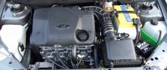
In any modern automobile engine, continuous fault diagnosis and adjustment of adjustment data are carried out using electronic systems. All VAZ injection engines, including the eight-valve engine on the 2110, are equipped with an engine management system. Each of the important indicators is monitored using a mass of sensors, and the knock sensor is one of them.
Knock sensor VAZ 2110 - purpose of the device
Detonation is a rather unpleasant phenomenon caused by spontaneous uncontrolled combustion of fuel in the combustion chamber.
It can occur due to many reasons - low-quality fuel or inappropriate compression ratio, incorrect operation of spark plugs.
But basically, detonation occurs due to an incorrectly set ignition timing.
A knock sensor will help identify the occurrence of undesirable phenomena in engine operation.
It is in this case that the knock sensor will help to determine the occurrence of an undesirable process at the very initial stage and transmit information about the beginning of detonation to the electronic engine control unit. The ECU, in turn, will adjust the ignition timing automatically to counteract the incipient detonation.
Pros of a working sensor
A working knock sensor will completely relieve the engine from overheating, ensure fuel savings and optimal power and traction.
Operating principle and location
Ignition too early can result in engine overheating, detonation, loss of power and excessive fuel consumption. Too late - the same, but at the same time starting the engine, especially a cold one, is quite difficult.
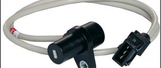
The piezoelectric knock sensor converts vibrations and noise in the cylinder head into an electrical impulse and transmits this data to the electronic control unit - the greater the one-time pressure on the sensor (micro-explosion, increased vibration), the stronger the signal from it.
The VAZ-2110 is equipped with two types of knock sensors.
There are two types of knock sensors:
- resonant type;
- broadband sensor.
Knock sensor diagram.
The first type of sensor is configured to oscillate at a certain frequency, it is more accurate and is used on cars manufactured after 2002–2003 . A wideband sensor perceives the entire spectrum of frequencies and its readings are approximate, and the range of the transmitted signal is quite wide.
The two types of sensors are not interchangeable, and before checking and installing a new one, you must know exactly what type of sensor is installed on the engine.
The knock sensor on the VAZ-2112 is located on the front of the engine, next to the oil dipstick.
The sensor is screwed into the cylinder block on the left side under the spark plugs; its replacement and diagnostics take a few minutes.
General electrical circuit VAZ-2111
- Block lights;
- Sound signal;
- Engine cooling fan electric motor;
- Starter VAZ-2111;
- Accumulator battery;
- Generator;
- Reversing light switch;
- Electric drive for locking the right front door lock;
- Power window relay;
- Starter activation relay;
- Heater motor;
- Micromotor-reducer for heater damper drive;
- Windshield washer motor;
- Washer fluid level sensor;
- Electric drive for locking the left front door lock;
- Right front door power window switch;
- Electric trunk lock;
- Additional resistor for heater fan motor;
- Windshield wiper gear motor;
- Left front door power window switch;
- Electric power window of the right front door;
- Door lock system control unit;
- Outdoor lighting switch;
- Brake fluid level sensor;
- Electric window lifter of the left front door;
- Indicator lamp for turning on the fog light;
- Fog light switch;
- Instrument cluster;
- Rear window heating indicator lamp;
- Rear window heating switch;
- Understeering's shifter;
- Fog light relay;
- Ignition switch;
- Mounting block;
- Illumination lamp for heater control levers;
- Hazard switch;
- Automatic heater control system controller;
- Glove compartment lamp;
- Glove compartment lamp switch;
- Cigarette lighter;
- On-board control system display unit;
- Ashtray lighting lamp;
- Socket for portable lamp;
- Instrument lighting switch;
- Electric drive for locking the right rear door;
- Right rear door power window switch;
- Watch VAZ-2111;
- Electric window lift of the right rear door;
- Brake light switch;
- Electric window lifter of the left rear door;
- Left rear door power window switch;
- Electric drive for locking the left rear door;
- Side direction indicators;
- Parking brake warning lamp switch;
- Luggage compartment lighting;
- Individual lighting lamp;
- Interior lighting;
- Heating system temperature sensor;
- Switches in the front door pillars;
- Switches in the rear door pillars;
- Exterior tail lights;
- Interior tail lights;
- License plate lights;
- Rear window wiper motor;
- Rear window washer motor;
A – Pads for connecting the right front speaker; B – Pads for connecting audio equipment; B – 110: Blocks for connecting the rear window washer motor; G – Pads for connecting the left front speaker; D – Block for connecting the injection system wiring harness; E – Connector for diagnosing electric power steering; G – Connector for diagnosing the automatic heater control system; 3 – Pads for connecting the right rear speaker; I – Pads for connecting the left rear speaker; K – socket for connecting the on-board computer; L – to the electric trunk lock; M – Blocks for connecting additional brake signals; H – to the rear window heating element.
A more detailed diagram of the same thing, consisting of two parts:
Symptoms of a problem
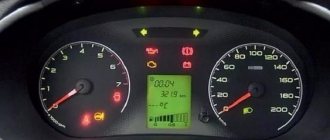
Before replacing the knock sensor, make sure that it is not working. Most often, sensor failure is due to an open circuit. This is expressed primarily in engine overheating and loss of power. In addition, the Check Engine warning light may come on when the load on the engine increases , the engine may stall and operate unstably regardless of speed.
When the knock sensor fails, the Check Engine light comes on.
Search
The easiest way to start troubleshooting is by reading the error codes. Depending on the type of error, we will take appropriate measures:
- code 0325 indicates that there is no contact in the sensor circuit, most likely the sensor connectors have oxidized, and in this case it is enough to ring its circuit and clean the contacts;
- with the same error, it is possible that the timing belt has slipped one tooth; it does not hurt to check the correct installation of the belt according to the marks;
- 0326, 0327 — low signal from the knock sensor, first let’s check the contacts and the tightening torque of the device fixing nut, it needs to be tightened with a force of 10–23 Nm, only then the sensor will work correctly;
- 0328 - the signal from the sensor exceeds the norm, this error basically indicates a malfunction of the sensor.
Depending on the manufacturer, the price of the sensor can be either 1200 rubles (Bosch, article number 2112–3855010 or 0 261 231 046 ), or 200–300 rubles for a domestically produced device. Their articles are 18.3855–01/18.3855 , 18.3855–01 and 2112–3855010 .
Stable operation of the 8-valve injector of the VAZ 2110 is ensured by a number of sensors. Each of them performs specific functions. Therefore, the failure of one regulator prevents the transfer of information to the electronic control unit. As a result, the ECU does not send signals to the power unit or transmits incorrect information.
Today, no one doubts that an injection engine demonstrates maximum efficiency and efficiency compared to a carburetor unit. Electronic fuel injection into the cylinders is one of the functions of the injector and provides it with a number of advantages.
Stable system operation, increased power and reliability are only possible if the electronics are functioning properly.
The functionality of the system is directly related to the huge number of sensors, which are the topic of this article, in particular:
- crankshaft sensor;
- speed;
- DTZHO;
- air regulator;
- turning on the fan;
- TPDZ;
- detonation.
Let us dwell in more detail on the listed, as well as some other regulators.
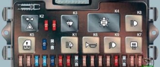
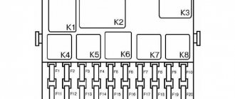
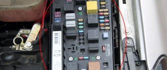
Fuse and relay box
The VAZ-2111 relay and fuse mounting block is located on the left side of the steering column in the instrument panel. To access the unit, press the latch switch and lower the unit down.
K1 - lamp health monitoring relay;
K2 - windshield wiper relay;
KZ - relay-interrupter for direction indicators and hazard warning lights;
K4 - headlight low beam relay;
K5 - headlight high beam relay;
K6 - additional relay VAZ-2111;
K7 — relay for turning on the heated rear window;
K8 - rear fog lamp relay;
F1-F20 - fuses
| Number | Current, A | Description of fuses |
| F1 | 5 | License plate lamps. Instrument lighting lamps. Side light indicator lamp. Trunk light. Left side marker lamps |
| F2 | 7,5 | Left headlight (low beam) |
| F3 | 10 | Left headlight (high beam) |
| F4 | 10 | Right fog lamp |
| F5 | 30 | Door window motors |
| F6 | 15 | Portable lamp (socket) VAZ2111 |
| F7 | 20 | Engine cooling fan electric motor. Sound signal |
| F8 | 20 | Rear window heating element. Relay (contacts) for turning on the heated rear window |
| F9 | 20 | Recirculation valve*. Windshield and headlight cleaners and washers (wiper protection). Relay (coil) for turning on the rear window heating |
| F10 | 20 | Spare |
| F11 | 5 | Starboard side marker lamps |
| F12 | 7,5 | Right headlight (low beam) |
| F13 | 10 | Right headlight (high beam). High beam warning lamp |
| F14 | 10 | Left fog lamp |
| F15 | 20 | Electrically heated seats. Trunk lock lock |
| F16 | 10 | Relay-breaker for direction indicators and hazard warning lights (in hazard warning mode). Hazard warning lamp |
| F17 | 7,5 | Interior lighting lamp. Individual backlight lamp. Ignition switch illumination lamp. Brake light bulbs. Clock (or trip computer) |
| F18 | 25 | Glove box lighting lamp. Heater controller (heater fuse). Cigarette lighter fuse for VAZ 2110, VAZ 2111, VAZ 2112. |
| F19 | 10 | Locking door locks. Relay for monitoring the health of brake light lamps and side lights. Direction indicators with warning lamps. Reversing lamps. Generator excitation winding. On-board control system display unit*. Instrument cluster. Clock (or trip computer) |
| F20 | 7,5 | Rear fog lamps |
A fog lamp fuse is installed in the niche of the instrument panel behind the mounting block. The central locking fuse is located behind the fuse box in a plastic box. And additional relays and fuses (all 15 A) are located in the cabin on the right side of the instrument panel behind the side trim attached with two screws.
- 1 — ignition module, controller;
- 2 — canister purge valve, vehicle speed sensor, oxygen concentration sensor (heating), air flow sensor VAZ-2111;
- 3 - fuel pump relay, fuel pump fuse, injectors.
- 4 — electric fan relay;
- 5 - fuel pump relay,
- 6 - main relay (ignition relay).
Relay and fuse box diagram
This is a schematic diagram of the VAZ 2111 relay and fuse mounting block. The outer number in the wire tip designation is the block number, and the inner number is the conventional number of the plug.
| Block | № | Color | Electrical circuits |
| Ш1 | 1 | ZhCh | fog lamp (left) |
| 2 | GP | trunk lock motor, heated seats | |
| 3 | R | door lock relay | |
| 4 | ABOUT | power window relay | |
| 5 | ZhP | fog light relay | |
| 6 | AND | fog lamp (right) | |
| 7 | MS | power window relay | |
| 8 | — | reserve | |
| Ш2 | 1 | — | reserve |
| 2 | — | reserve | |
| 3 | — | reserve | |
| 4 | H | weight " - " | |
| 5 | ZhP | size (left rear) | |
| 6 | Warhead | outdoor light switch | |
| 7 | — | reserve | |
| 8 | ZhCh | license plate lamps, off instrument lighting | |
| 9 | KP | size (right rear) | |
| 10 | TO | size (right) | |
| 11 | ZhG | email windshield wiper motor, windshield wiper and washer switch. | |
| 12 | Z | outdoor light switch | |
| 13 | ABOUT | fog light switch | |
| 14 | Emergency | hazard switch | |
| 15 | — | reserve | |
| 16 | GP | Ignition switch (terminal 15), steering column switch | |
| 17 | R | windshield wiper and washer switch | |
| 18 | JV | steering column headlight switch | |
| 19 | — | reserve | |
| 20 | — | reserve | |
| 21 | AND | size (left) | |
| Ш3 | 1 | midrange | low beam (left headlight) |
| 2 | — | reserve | |
| 3 | WITH | low beam (right headlight) | |
| 4 | R | generator (cl. 30) | |
| 5 | TO | generator (cl. 30) | |
| 6 | TO | generator (cl. 30) 2111 | |
| Ш4 | 1 | PZ | on-board display system |
| 2 | GO | hazard switch | |
| 3 | IF | hazard switch | |
| 4 | H | weight " - " | |
| 5 | PG | portable lamp plug | |
| 6 | Salary | heated rear window switch, heated rear window lamp | |
| 7 | — | reserve | |
| 8 | — | reserve | |
| 9 | — | reserve | |
| 10 | ZhZ | steering column washer and windshield wiper switch | |
| 11 | B | email windshield wiper motor | |
| 12 | BW | steering column washer and windshield wiper switch | |
| 13 | GB | steering column switch, ignition switch lamp | |
| 14 | BP | brake lights, clock, interior lamp | |
| 15 | P | brake lights | |
| 16 | RP | off brake lights | |
| 17 | ABOUT | generator (cl. 30) VAZ-2111 | |
| Ш5 | 1 | AF | high beam (left lamp) |
| 2 | JV | rear window heating element | |
| 3 | G | heater controller, glove compartment lamp | |
| 4 | Z | high beam (right lamp) | |
| 5 | ZhG | Windshield wiper motor, SAUO recirculation valve | |
| 6 | PB | email cooling fan, beep |
To locate the faulty fuse, use the table of circuits protected by fuses. Before this, of course, you need to find the cause of the blown fuse, eliminate it, and only then install a new one. The table shows the circuits that each fuse protects, but on each model some of them may not be installed due to the lack of certain devices (for example, power windows, lock drives and other units).
Source
Speed sensor
The device is located on the speedometer output shaft. If a malfunction occurs, the vehicle may not idle smoothly. The design is simple and reliable. The operating principle is based on the Hall effect. There were two types of meters installed on the ten - with a square and a round block.
When the speedometer needle jumps, it is recommended to check the device in question, since failure can affect the speed performance of the vehicle.
Signs of the need for internal combustion engine repair
The reasons why the operation of the engine is disrupted are arranged in a small list, starting with refusal to start and ending with floating idle speed (this problem was removed on the 127 “engine”). Not all breakdowns end in capital damage - sometimes it’s enough to add oil, sometimes it’s enough to adjust the ECU settings.
Compression reduction
A decrease in cylinder compression below 16 atmospheres is a bad sign. Such a high limit corresponds to a compression ratio of 11.
Knocks in the engine
Engine knocks can come from several points. These could be hydraulic compressors, timing belt rollers or pins. The knocking noise could also be caused by low oil level. The answer to the question will be given by a thorough detailed inspection of all parts of the unit and checking the oil level.
Blue smoke from the exhaust pipe
The blue smoke that comes from the exhaust pipe appears when oil enters the combustion chamber. It can leak either from the valves or from under the piston. The result is the same: the oil is eaten up and blue smoke pours out of the chimney. Once the leak is located, half the problem will already be solved.
Troit motor
Sometimes in the cold the engine may stall - don’t be alarmed by this, because it may simply be one of the spark plugs that fails. In this case, we advise you to simply restart the engine and it will stop running.
How much does it cost to overhaul a Priora engine - average price
Self-repair of a Priora engine with 16 valves costs an average of 16-20 thousand rubles. The cost depends on the severity of the breakdown and may be lower or higher than this average range. Repairing a Priora engine can be entrusted to the wrong hands, but then you will have to pay for the work - sometimes the cost of repairs reaches as much as 40 thousand rubles.
This is an unreasonably inflated figure, because, as practice shows, you can rebuild the engine on a Priora, working at a moderate pace, in just three days - and three days of work is definitely not worth that kind of money. Don’t be afraid of not being able to cope - your Lada is easy to repair, and using the advice and “tutorials”, you will conquer even such a task that is impossible at first glance.
DTZO: temperature indicator
The regulator screws directly into the cooling system pipe. Located between the filter housing and the power unit. The task of the coolant sensor is as follows:
- when starting a cold engine – informing the system about the supply of an enriched mixture;
- if it overheats, turn on the fan to cool the radiator.
If we talk about carburetor engines, then one of the listed functions was performed by the choke. The measuring element (DTZO) plays an important role for the stable operation of the power unit. It is characterized by the following problems:
- violation of contacts;
- high probability of failure if the fan starts when the engine is cold;
- difficulty starting a hot engine;
- increased fuel consumption if the indicator fails.
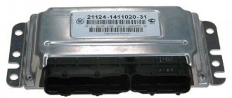
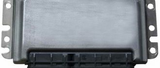
Instructions for removing and replacing the computer
The need to dismantle the ECM unit 16 of the ten valve engine arises if repairs are necessary when faults are identified. The repair process itself will depend on what exactly happened in the operation of the ECU. For example, if the contacts on the module connector have oxidized, the unit must be dismantled to clean or replace them. If the reason lies in damage to the housing, then the device must be removed for replacement; if water has gotten inside, then the module should be removed in order to dry it. Only after you have dried the block can it be tested.
If the problem lies in the performance of the board and some burnt-out elements, then you can try to repair it yourself by re-soldering some components. But we would still recommend turning to specialists for help, especially if you have never encountered such a problem before (the author of the video about repairing the control controller is Vyacheslav Chistov).
Work sequence
Before dismantling the device, you should disconnect the negative terminal from the car battery:
Do not repair the control unit if you have never had to deal with such a task before!
Mass air flow sensor: air regulator
The tens electronic system needs information about the amount of air required. This is necessary to create the optimal volume of the warm-air mixture.
Considering the sensors of the VAZ 2110 injector 8 valves , it should be noted that the mass air flow sensor is the most sensitive of all devices.
A small amount of moisture or dust can cause damage. This must be taken into account during the car repair process. So, the sensor determines the volume of air before entering the system. The disadvantages of the device are:
- sensitivity to moisture and dust;
- malfunctions during operation of the power unit at idle speed;
- increased fuel consumption;
- difficulty starting the engine;
- at increased speeds and significant loads, the power unit may stop abruptly.
All of the above reasons are due to the fact that a mixture that is too lean (or rich) gets into the cylinders. The operating principle of the device in question is quite simple. There are several heating elements inside the structure, which “lose” temperature as air passes through. The more electricity used to heat these components, the more air enters the system.
Thus, the change in electrical power is directly related to air flow. The information is transmitted to the system, which turns on the appropriate modes and controls air flow.
Fan sensor
This tool is necessary for measuring temperature and then turning on a fan designed to cool the engine. Unlike other devices, it is reliable and has a long service life. The sensor is filled with a solid substance that expands as the temperature increases. By purchasing high-quality products, owners of the VAZ-2110 model will be able to forget about the need for replacement for a long time.
The task of the device in question is reduced to transmitting a signal to the computer as a result of pressing the gas pedal. Thus, the amount of fuel injected increases. The design of the regulator is quite reliable. Failure is indicated by jerking when pressing the accelerator pedal. Also, sometimes “failures” occur. A regular tester is used for testing.
If the damper is closed, the voltage is about 0.5 Volts. When you press the pedal as hard as possible, the voltage increases to 4 volts.
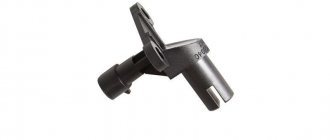
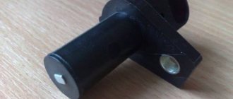
Knock sensor
The device is mounted on the cylinder block. Its function is reduced to transmitting information about detonation to the electronic control unit. As a result of increased detonation, the ECU (in accordance with the software) changes the operation of the power unit. Dozens of recent series have piezoceramic devices installed. Functionality testing is performed using a tester. To do this, you need to connect the meter to the contacts of the device and lightly knock. The measuring device should record voltage drops, which indicates proper operation.
There are other sensors, such as valve timing and a lambda probe, that can be installed on cars with 8 and 16 valves. To study the features of each device, it is recommended to use the instruction manual for the VAZ 2110 car.
Any modern car is equipped with many different sensors that allow the driver to know about the condition and performance of certain components. And the VAZ 2110 car is no exception; in this article we will talk about what sensors are used in it and what their location is.
As you know, the VAZ 2110 injector with 8 or 16 valves is significantly superior to the carburetor version in many ways. At least because in this case the supply of gasoline, as well as the combustible mixture, is regulated by electronics. Accordingly, the use of electronics implies the use of many different regulators and controllers. Their breakdown can lead to certain consequences, so the car owner should always know what certain regulators are responsible for. Below we consider almost all VAZ sensors that are in the top ten.
The power unit of the "tens" is controlled using the ECM - an electronic system. This system must always know how much air needs to be supplied for a certain volume of gasoline. These two parameters are closely related to each other, since with their help a combustible mixture with the required density is formed in the engine power unit. After the system determines the required volume of air, it begins to select the appropriate amount of gasoline. As for the regulator, it is responsible for the suction volumes.
Throttle controller
Designed for dosing fuel in cylinders. When you press the gas pedal on an injection engine, only the air damper mechanically opens. The amount of gasoline to create the working mixture changes according to a command from the ECU. This is what the throttle position sensor (TPS) is designed for.
The controller is a variable resistance, essentially the same as the volume control on a car radio. Only the voltage supplied to the control unit changes here. Roughly speaking, TPS converts the force of pressing the gas pedal into a certain electrical signal. It goes to the ECU, in which the voltage/fuel quantity relationship is hard-wired with great precision.
The signal amplitude varies from 0.7 to 4 V (with the damper fully open). The incoming gasoline also changes linearly. The TPS is installed directly on the throttle assembly.
Coolant temperature sensor
On the VAZ 2110, sensors can be used for different purposes, but most of them are mounted in the engine compartment. On an 8 or 16 valve engine, the fan sensor is a device designed to activate the fan. We are talking directly about a fan designed to cool a hot engine.
The controller turns on automatically when the power unit reaches a certain temperature. But it can also turn on when the engine is off. At first, this fact may be alarming for many owners of the “ten”, but there is nothing wrong with it, so there is no need to worry.
It is necessary to highlight the advantages of this controller:
- As practice has shown, the fan sensor is one of the most reliable vehicle devices, since its design is based on a solid filler. When the ambient temperature increases, this filler begins to expand.
- The design of this device also includes a special spring-loaded lever. Thanks to this component, no defects occur during the operation of the regulator.
- The device prevents sparks from appearing, which is especially important for ensuring vehicle safety.
- In fact, this type of regulator itself is reliable. If you buy a high-quality device, then in the future you will notice that it will function for quite a long time; you can forget about the need to replace it for the next few years.
How to independently diagnose the unit?
At first glance, it may seem that diagnosing an ECU is a difficult task that not everyone can handle. Indeed, checking your block is not so easy, but having theoretical knowledge, it is quite possible to apply it in practice.
Required tools and equipment
To check the functionality of the module yourself, you will need to perform a number of steps to connect to the ECU.
To perform the test you will need the following devices and elements:
- Oscilloscope. It’s clear that not every car enthusiast has such a device, so if you don’t have one, you can use a computer with the necessary diagnostic software pre-installed on it.
- Cable for connecting to the device. You need to select an adapter that supports the KWP2000 protocol.
- Software. Finding diagnostic software today is not a problem. To do this, just monitor the network and find a program that is suitable for your vehicle. The program is selected taking into account the car, since different control units are installed on different cars.
Algorithm of actions
The diagnostic procedure for the electronic control system is discussed below using the Bosch M 7.9.7 module as an example. This control unit model is one of the most common not only in domestic VAZ cars, but also in foreign-made cars. It should also be noted that the verification process is described using the example of using the KWP-D software.
So, how to check the ECU at home:
First of all, the adapter used must be connected to a computer or laptop, as well as the ECM itself. To do this, connect one end of the cable to the output on the unit, and the other to the USB output on the computer. Next, you need to turn the key in the car's ignition, but you do not need to start the engine. By turning on the ignition, you can launch the diagnostic utility on your computer. After completing these steps, a window with a message should pop up on the computer screen, which confirms the successful start of diagnosing malfunctions in the controller. If for some reason the message does not appear, you need to make sure that the computer successfully connected to the controller
Check the quality of the connection and connection of the cable to the unit and laptop. Then a table should be displayed on the laptop display, which will indicate the main technical characteristics and operating parameters of the vehicle. At the next stage, you need to pay attention to the DTC section (it may be called differently in different programs). This section will present all the faults with which the power unit operates
All errors will be displayed on the screen in the form of encrypted combinations of letters and numbers. To decipher them, you need to go to another section, which is usually called Codes, or use the technical documentation for your car. If there are no errors in this section, then you now don’t have to worry, since the vehicle’s engine is working perfectly (the author of the video about ECU repair at home is the AUTO REZ channel).
But this verification option is most relevant if the computer sees the block. If you have problems connecting to it, then you will need an electrical diagram of the device, as well as a multimeter. The tester or multimeter itself can be purchased at any specialty store, and the electrical circuit diagram of the ECM should be in the service manual. The diagram itself needs to be studied most carefully; this will be required for verification.
In the event that the ECM points to a specific block, and does not show erratic data, then in accordance with the diagram it needs to be found and called. If there is no accurate information, then the only way out is to diagnose the entire system; as we said above, breakdowns are considered one of the main faults.
After the breakdown is found, it is necessary to check the resistance and determine exactly where the cable is fixed. You will need to solder the corresponding new wire parallel to the old one; if the reason lies in the breakdown, then these actions will eliminate the problem. In all other cases, only qualified specialists can solve the problem.
Crankshaft regulator
Depending on the type of car, on a 16- and 8-valve engine, the location of all controllers may be different. However, all of these devices combine into one functioning system, and the crankshaft adjuster is no exception. Thanks to this controller, the electronic engine management system of the “tens” can independently determine at what point to supply gasoline and a spark through the spark plugs in order to ignite the combustible mixture. In fact, the design of the device is a magnet, as well as a coil of thin wire.
The crankshaft sensor has certain advantages:
- As practice shows, at “tens” this regulator can work for quite a long time. Its service life does not decrease even as a result of using the vehicle’s power unit under increased loads.
- The crankshaft adjuster works in conjunction with the crankshaft pulley.
- If the device fails, the engine may not be able to start. Or, if the regulator breaks down, the speed parameters will be reduced to 3.5 thousand per minute.
This controller is installed on the oil pump, actually at the very top of the shaft teeth. Or rather, one millimeter from the cloves. You can learn more about how to replace this controller yourself from the video below (the author of the video is the channel In Sandro’s Garage).
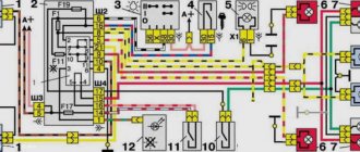
VAZ-2111 diagram
The free collection of materials to help auto electricians contains all the necessary documentation on the electrical equipment of the VAZ-2111 car - general circuit diagram, switching system, electronic engine control module, relay block with fuses and other components. The VAZ 2111 car is a station wagon (production from 1998 to 2014), which is a modernized concept of the rear-wheel drive VAZ-2104. Here the wiring diagram for the injector and a number of other components have been slightly changed, as can be seen from the electrical diagrams and harnesses.
Coolant temperature indicator
Antifreeze or coolant is used to cool the engine. To ensure proper operation of the power unit, the coolant also has its own controller. In its functionality, this regulator is vaguely reminiscent of the choke that is equipped with 8- and 16-valve carburetor engines of the “ten” and other vehicles. The sensor itself is designed to monitor the temperature of the consumable.
Installing a new antifreeze sensor
In fact, this device also provides fuel regulation. If the power unit is running cold and has not yet warmed up, it will receive more gasoline for normal operation. Readings about the coolant temperature are displayed on the control panel in the vehicle interior. In accordance with these indicators, the driver will always be able to find out about the overheating of the unit by the way the sensor arrow on the dashboard begins to move into the red zone.
The antifreeze temperature sensor periodically fails; it is characterized by the following malfunctions:
- Loss of electrical contact inside the controller, resulting in its inoperability.
- The device is installed in such a way that it may be exposed to moving elements, particularly the accelerator pedal cable. It would be even more correct to say that the cable does not act on the sensor itself, but on its wires, which in fact can lose insulation as a result of long-term use.
- Often the regulator breaks down if the ventilation device starts to function on an engine that is not warmed up.
- If the motor is overheated, it may be difficult to start.
- If the fuel temperature controller fails, it can lead to increased gas mileage. If you encounter one of these problems, then to ensure normal operation of the car engine, you need to replace the controller. Detailed replacement instructions are presented in the video below (author - REPAIR VAZ 2110, 2111, 2112).
Gasoline level indicator
The fuel sensor of the VAZ-2110, like any other car, is a rheostat made of nichrome wire. Its moving contact is mechanically connected to a float, which is located in the tank on the surface of the gasoline. The fuel level changes, and along with it the resistance of the rheostat, which is recorded by the device on the panel.
In addition, there is an indication of the reserve amount of gasoline. It works thanks to the same float. In a certain position, it closes the contacts, which causes the warning lamp to turn on. The fuel gauge cannot be called an accurate and reliable device. However, these are the disadvantages of all mechanical sensors. The main malfunctions are associated with damage to the nichrome wire, which simply wears out due to the constant movement of the “runner”.
The sensor is naturally installed in the tank, and replacing it does not present any difficulties. True, you will have to remove the fuel pump and partially drain the fuel if the car is “filled to capacity.”
Speed sensor
8- and 16-valve “tens” are also equipped with a speed sensor. Thanks to this device, the electronic engine control system receives information about how fast the vehicle is moving. The sensor itself is installed on the vehicle's gearbox. As practice has shown, on VAZ 2110 cars this controller is characterized by fairly high reliability and a long service life.
But domestic developers could not do everything perfectly, so this device is characterized by several malfunctions:
- If a component fails or does not work correctly, then when idling, the power unit may turn off on its own.
- A failed regulator can partially affect the speed characteristics of the vehicle. Of course, if the device breaks down completely, the driver will not be able to know how fast it is moving.
Two speed controllers
Electronic Engine Control System (ECM)
Location of engine control system elements in the engine compartment (engine mod. 2111)
| 1 – mass air flow sensor; 2 – coolant temperature sensor (installed on the cooling system pipe); 3 – knock sensor; 4 – adsorber for the gasoline vapor recovery system; | 5 – crankshaft position sensor (installed on the oil pump cover); 6 – throttle pipe (a throttle position sensor and an idle speed regulator are installed on it); 7 – speed sensor (installed on the gearbox) |
VAZ-2112 ECM diagram
| 1 – ignition relay 2 – ignition switch 3 – battery 4 – converter 5 – oxygen concentration sensor 6 – adsorber with solenoid valve 7 – air filter 8 – mass air flow sensor 9 – idle speed control 10 – throttle position sensor 11 – throttle unit 12 – diagnostic block 13 – tachometer 14 – speedometer 15 – “CHECK ENGINE” indicator lamp 16 – immobilizer control unit 17 – ignition module 18 – injector | 19 – fuel pressure regulator 20 – phase sensor 21 – coolant temperature sensor 22 – spark plug 23 – crankshaft position sensor 24 – knock sensor 25 – fuel filter 26 – controller 27 – fan switching relay 28 – electric cooling fan 29 – switching relay electric fuel pump 30 – fuel tank 31 – electric fuel pump with fuel level indicator sensor 32 – gasoline vapor separator 33 – gravity valve 34 – safety valve 35 – speed sensor 36 – two-way valve |
Characteristics and interchangeability of ECM components
| Engine | VAZ-2111, 8-cl. | |||||
| Controller | G.M. | "January-4.1" | M 1.5.4 | M 1.5.4 N or “January-5.1” | M 1.5.4 N or “January-5.1.1” | MP 7.0 |
| Controller markings | 2111-1411020-20 | 2111-1411020-22 | 2111-1411020-00 | 2111-1411020-60 or 2111-1411020-61 | 2111-1411020-70 or 2111-1411020-71 | 2111-1411020-40 |
| Neutralizer | Eat | No | No | Eat | No | Eat |
| Air flow sensor | GM, square body | BOSCH, round case | ||||
| Knock sensor | Resonant | Broadband | ||||
| Speed sensor | Circular connector | Rectangular or round connectors | Rectangular connector | |||
| Oxygen sensor | GM AFS-62, or AFS-79, or BOSCH LHS-24 | No | No | BOSCH LHS-25 | No | BOSCH LHS-25 |
| Camshaft and receiver | 2108 | 2110 | ||||
| Engine | VAZ-2112, 16-cl. | ||
| Controller | "January-4.1" | M 1.5.4 N or January-5.1″ | M 1.5.4 N or “January-5.1.2” |
| Controller markings | 2112-1411020-01 | 2112-1411020-40 or 2112-1411020-41 | 2112-1411020-70 or 2112-1411020-71 |
| Neutralizer | No | Eat | No |
| Air flow sensor | GM, square body | BOSCH, round case | |
| Knock sensor | Resonant | Broadband | |
| Speed sensor | Circular connector | Rectangular connector | |
| Oxygen sensor | No | BOSCH LHS-25 | No |
| Camshaft and receiver | 2112 | ||
On VAZ-2110, -2111 and -2112 vehicles, a variant version uses an electronic engine control system, i.e. distributed fuel injection system. This system is used on engines 2111 and 2112. It is called distributed injection because fuel is injected for each cylinder with a separate nozzle. The fuel injection system reduces exhaust emissions while improving the vehicle's driving characteristics.
There are distributed injection systems with and without feedback. Moreover, both systems can be equipped with imported or domestic components. Controllers (electronic control units) can also be installed in different types. All of these systems have their own characteristics in design, diagnostics and repair, which are described in detail in the corresponding separate repair manuals for specific fuel injection systems with a specific controller.
This chapter provides only a brief description of the general principles of the design, operation and diagnostics of fuel injection systems using the example of a system with a “January-4” controller.
The feedback system is used mainly on export vehicles. It has a neutralizer and an oxygen sensor installed in its exhaust system, which provides feedback. The sensor monitors the oxygen concentration in the exhaust gases, and the controller uses its signals to maintain an air/fuel ratio that ensures the most efficient operation of the converter.
In an injection system without feedback, a converter and an oxygen sensor are not installed, and a CO potentiometer is used to adjust the CO concentration in the exhaust gases. This system also does not use a gasoline vapor recovery system. It is possible to have an injection system without a CO potentiometer, in which case the CO content is regulated using a diagnostic tool.
There is also a system of sequential distributed fuel injection or phased injection. It is used with the 2112 engine. A phase sensor is additionally installed here, which determines the moment of the end of the compression stroke in the 1st cylinder, and fuel is supplied by injectors to the cylinders in a sequence corresponding to the ignition order in the cylinders (1–3–4–2). ATTENTION !
1. Before removing any components of the injection control system, disconnect the wire from the negative terminal of the battery.
2. Do not start the engine if the cable ends on the battery are not tightened properly.
Never disconnect the battery from the vehicle's on-board power supply while the engine is running.
4. When charging the battery, disconnect it from the vehicle's on-board power supply.
5. Do not expose the controller to temperatures above 65°C when in operation and above 80°C when not in operation (for example, in a drying chamber). It is necessary to remove the controller from the car if this temperature is exceeded.
6. Do not disconnect or connect the wiring harness connectors from the controller while the ignition is on.
7. Before performing arc welding on a vehicle, disconnect the wires from the battery and the wire connectors from the controller.
8. Perform all voltage measurements with a digital voltmeter with an internal resistance of at least 10 MOhm.
9. Electronic components used in the injection system are designed for very low voltage and therefore can easily be damaged by electrostatic discharge. To prevent ESD damage to the controller:
– do not touch the controller plugs or electronic components on its boards with your hands;
– when working with the controller EPROM, do not touch the microcircuit pins.
Ignition system
Ignition system diagram
| 1 - accumulator battery; |
The ignition system does not use a traditional distributor and ignition coil. Here, an ignition module 5
, consisting of two ignition coils and high-energy control electronics. The ignition system has no moving parts and therefore requires no maintenance. It also has no adjustments (including ignition timing), since the ignition is controlled by the controller.
The ignition system uses a spark distribution method called the "idle spark" method. The engine cylinders are combined into pairs 1–4 and 2–3 and sparking occurs simultaneously in two cylinders: in the cylinder in which the compression stroke ends (working spark), and in the cylinder in which the exhaust stroke occurs (idle spark). Due to the constant direction of current in the windings of the ignition coils, the sparking current for one spark plug always flows from the central electrode to the side electrode, and for the second, from the side to the central one. Spark plugs are used type A17DVRM (for 8-valve engines) or AU17DVRM (for 16-valve engines, with a key size reduced to 16 mm). The gap between the spark plug electrodes is 1.0–1.15 mm.
The ignition in the system is controlled using a controller. The crankshaft position sensor provides a reference signal to the controller, on the basis of which the controller calculates the firing sequence of the coils in the ignition module. To accurately control the ignition, the controller uses the following information:
– crankshaft rotation speed;
– engine load (mass air flow);
– coolant temperature;
– position of the crankshaft;
– presence of detonation.
Evaporative emission system
This system is used in a closed loop injection system. The system uses the method of vapor capture with a carbon adsorber. It is installed in the engine compartment and connected by pipelines to the fuel tank and throttle pipe. There is an electromagnetic valve on the adsorber cover, which, based on signals from the controller, switches the operating modes of the system.
When the engine is not running, the solenoid valve is closed and gasoline vapors from the fuel tank flow through the pipeline to the adsorber, where they are absorbed by granular activated carbon. When the engine is running, the adsorber is purged with air and vapors are sucked to the throttle pipe and then into the intake pipe for combustion during the operating process.
The controller controls the purge of the adsorber, including the solenoid valve located on the adsorber cover. When voltage is applied to the valve, it opens, releasing vapor into the intake pipe. The valve is controlled by pulse width modulation. The valve turns on and off at a frequency of 16 times per second (16 Hz). The higher the air flow, the longer the duration of the valve activation pulses.
The controller turns on the canister purge valve when all of the following conditions are met:
– coolant temperature above 75 °C;
– the fuel supply control system operates in a closed loop mode (with feedback);
– vehicle speed exceeds 10 km/h. Once the valve is turned on, the speed criterion changes. The valve will only turn off when the speed decreases to 7 km/h;
– throttle opening exceeds 4%. This factor does not matter in the future if it does not exceed 99%. When the throttle valve is fully opened, the controller turns off the canister purge valve.
Injection system
The amount of fuel supplied by the injectors is regulated by an electrical pulse signal from the controller (electronic control unit). The controller monitors engine condition data, calculates fuel demand and determines the required duration of fuel supply to the injectors (pulse duration). To increase the amount of fuel supplied, the pulse duration increases, and to reduce the fuel supply, it decreases.
The controller has the ability to evaluate the results of its calculations and commands, as well as remember the experience of recent work and act in accordance with it. “Self-learning” of the controller is a continuous process that continues throughout the entire life of the vehicle.
Fuel is supplied using one of two different methods: synchronous, i.e. at a certain position of the crankshaft, or asynchronous, i.e. independently or without synchronization with the rotation of the crankshaft. Synchronous fuel injection is the predominantly used method. Asynchronous fuel injection is used mainly during engine start-up mode.
The injectors are turned on in pairs and alternately: first, the injectors of the 1st and 4th cylinders, and after 180° of rotation of the crankshaft - the injectors of the 2nd and 3rd cylinders, etc. Thus, each injector is turned on once per revolution of the crankshaft, i.e. twice per full engine operating cycle.
Regardless of the injection method, fuel supply is determined by the condition of the engine, i.e. its mode of operation. These modes are provided by the controller and are described below.
Initial fuel injection. When the engine crankshaft begins to turn with the starter, the first impulse from the crankshaft position sensor causes an impulse from the controller to turn on all the injectors at once. This serves to speed up engine starting.
Initial fuel injection occurs every time the vehicle is started. The duration of the injection pulse depends on the temperature. On a cold engine, the injection pulse increases to increase the amount of fuel, and on a warm engine, the pulse duration decreases. After the initial injection, the controller switches to the appropriate injector control mode.
Engine start mode. When the ignition is turned on, the controller turns on the electric fuel pump relay, and it creates pressure in the fuel supply line to the fuel rail. The controller checks the signal from the coolant temperature sensor and determines the correct air/fuel ratio for starting.
After the crankshaft begins to rotate, the controller operates in start-up mode until the speed exceeds 400 rpm or the “flooded” engine purge mode begins.
Engine purge mode. If the engine is "flooded" (i.e. fuel has wet the spark plugs), it can be cleared by opening the throttle fully while cranking the crankshaft. In this case, the controller does not supply injection pulses to the injectors, and the engine must be “cleaned”. The controller maintains this mode as long as the engine speed is below 400 rpm and the throttle position sensor indicates that it is almost fully open (more than 75%).
If the throttle valve is held almost fully open when starting the engine, the engine will not start because when the throttle valve is fully open, no injection pulses are sent to the injector.
Operating mode of fuel supply control. After starting the engine (when the speed is more than 400 rpm), the controller controls the fuel supply system in operating mode. In this mode, the controller calculates the pulse duration to the injectors based on signals from the crankshaft position sensor (rotation speed information), mass air flow sensor, coolant temperature sensor and throttle position sensor.
The calculated injection pulse duration may result in an air/fuel ratio other than 14.7:1. An example would be a cold engine, which requires a rich mixture to ensure good driving performance.
Operating mode for a closed-loop injection system. In this system, the controller first calculates the pulse duration to the injectors based on signals from the same sensors as in the open-loop injection system. The difference is that in a closed-loop system, the controller still uses the signal from the oxygen sensor to adjust and fine-tune the calculated pulse to accurately maintain the air/fuel ratio between 14.6 and 14.7:1. This allows the catalytic converter to operate at maximum efficiency.
Operation of the system with sequential (phased) fuel injection. The difference between this system and those described above is that the controller turns on the injectors not in pairs, but sequentially, in the firing order of the cylinders (1-3-4-2). The phase sensor gives the controller a signal when the 1st cylinder is at TDC at the end of the compression stroke. Based on this signal, the controller calculates the moment when each injector is turned on, and each injector injects fuel once every two revolutions of the engine crankshaft, i.e. in one full working cycle. This method allows you to more accurately dose fuel into the cylinders and reduce the level of toxicity of exhaust gases.
Enrichment mode during acceleration. The controller monitors sudden changes in throttle position (via the throttle position sensor) and the signal from the mass air flow sensor and provides additional fuel by increasing the duration of the injection pulse. The rich acceleration mode is used only to control fuel delivery under transient conditions (when the throttle valve is moved).
Power enrichment mode. The controller monitors the throttle position sensor signal and engine speed to determine when the driver needs maximum engine power. To achieve maximum power, a rich fuel mixture is required, and the controller changes the air/fuel ratio to approximately 12:1. In a closed-loop injection system in this mode, the signal from the oxygen concentration sensor is ignored, since it will indicate a rich mixture.
Lean mode when braking. When braking a vehicle with the throttle closed, emissions of toxic components into the atmosphere may increase. To prevent this, the controller monitors the decrease in the throttle opening angle and the signal from the mass air flow sensor and promptly reduces the amount of fuel supplied by reducing the injection pulse.
Fuel supply cut-off mode when engine braking. When braking with the engine in gear and clutch engaged, the controller can completely turn off the fuel injection pulses for short periods of time. The fuel supply is turned off and on in this mode when certain conditions are met regarding coolant temperature, crankshaft speed, vehicle speed and throttle opening angle.
Supply voltage compensation. If the supply voltage drops, the ignition system may produce a weak spark, and the mechanical movement of the injector “opening” may take longer. The controller compensates for this by increasing the energy accumulation time in the ignition coils and the duration of the injection pulse.
Accordingly, as the battery voltage (or the voltage in the vehicle’s on-board network) increases, the controller reduces the time of energy accumulation in the ignition coils and the injection duration.
Fuel cut-off mode. When the ignition is turned off, fuel is not supplied by the injector, which prevents self-ignition of the mixture when the engine is overheated. In addition, fuel injection pulses are not supplied if the controller does not receive reference pulses from the crankshaft position sensor, i.e. this means the engine is not running.
The fuel supply is also cut off when the maximum permissible engine speed of 6510 rpm is exceeded to protect the engine from over-torque.
Cooling system electric fan control. The electric fan is turned on and off by the controller depending on the engine temperature, crankshaft speed, air conditioning operation (if the car has one) and other factors. The electric fan is activated by an auxiliary relay located under the instrument panel console on the right side.
When the engine is running, the electric fan turns on if the coolant temperature exceeds 104 ° C or a request is given to turn on the air conditioning. The electric fan turns off when the coolant temperature drops below 101 °C, after the air conditioning is turned off or the engine is stopped.
Phase sensor
This sensor is not installed on 8-valve engines; it is present only on 16-valve versions of the “ten”. The main purpose of the controller is to provide the necessary data to the power unit control system. In accordance with these data, the system determines at what point in time and where to inject fuel, into which specific cylinder. Every owner of a VAZ 2110 should know where this device is located. If you open the engine compartment of the car, you will see that the regulator is located on the right side of the neck for filling the engine fluid.
In principle, if the regulator breaks, nothing bad will happen if you look at it from the point of view of the integrity of the vehicle. But failure of the controller will in any case provoke an increase in gasoline consumption. This is due to the fact that the electronic control system of the internal combustion engine will independently switch the gas distribution mechanism to standby mode. Accordingly, gasoline will begin to be supplied to all cylinders of the engine at once. And at first, the driver may not even know about it until he diagnoses the regulator or measures fuel consumption.
New phase sensor for VAZ 2110
Naturally, such a model of the domestic automobile industry as the “ten” is not the most modern and advanced car in terms of electronics. However, machines of this model are equipped with a wide variety of regulators and controllers. In this article, we did not talk about all the devices, but only about the most basic ones that every motorist should know about. You can find more detailed information in other articles on our website or in the service book for your car.
Modifications of VAZ-2111
- VAZ-21111 with an opening rear door, station wagon with a 1.5-liter carburetor engine.
- VAZ-21110 is equipped with an injection 8-valve engine with a working volume of 1.5 liters.
- VAZ-21112 station wagon with an injection 8-valve engine with a volume of 1.6 liters and a power of 80 hp. With.
- VAZ-21113 with a 16-valve injection engine with a volume of 1.5 liters.
- VAZ-21114 with a 16-valve injection engine 1.6 liters 89 horsepower.
- VAZ-21116 - 04 all-wheel drive station wagon equipped with a 2-liter Opel C20XE engine with a capacity of 150 horses. It featured enlarged wheel arch cutouts, a redesigned bumper skirt with integrated fog lights and an updated aerodynamic shield over the rear.
- VAZ-2111-90 “Tarzan-2” is an all-wheel drive station wagon built on the basis of the VAZ-2111, produced since 1999. Like the previous generation of Tarzans, the body of the VAZ-2111 car was mounted on a Niva frame, and the rear suspension of the car was independent.
Idle speed control
Today, in urban environments, drivers simply cannot do without idling. Therefore, every car, including the VAZ 2110, is equipped with an idle speed sensor. Incorrect operation or failure of this regulator will significantly complicate driving, because it will cause the engine to stop even during the shortest stops. So if the controller fails, and this is not uncommon in VAZ 2110 cars, it needs to be changed as quickly as possible.
Removing the idle air control
The main purpose of this type of regulator is to support the speed required for normal operation of the power unit. Thanks to the device, the driver can always make a short stop as a result of changing the incoming air volume. As for the location, this controller is installed on the throttle line. In particular, we are talking about an anchor stepper motor, which is equipped with two windings.
When a corresponding signal is received on one of the windings, a special needle moves forward one step and backwards one step. Thanks to the worm gear, the device rotates, which is produced using a stepper motor, thus converting this movement into translational. The rod itself, namely its conical part, is located in the line through which the air flow is supplied.
Thanks to the functioning of the rod, the system adjusts the idle speed of the power unit. The rod from the device, as mentioned above, can be retracted or extended. In this case, it all depends on what kind of pulse will be supplied from the regulator. The controller itself allows you to adjust the frequency at which the engine crankshaft will rotate when the machine is stopped for a short time.
In addition, the controller controls the incoming air flow, which bypasses the throttle in the closed position. When the engine is warmed up, the regulator, by controlling the movement of the rod itself, at idle speed allows you to maintain the required crankshaft speed. In this case, the load and condition of the power unit do not play a role.
Mass air flow sensor
One of the most capricious and delicate sensors of the VAZ-2110 injector. However, it is also quite expensive. The sensor measures the amount of air passing through the car filter and transmits the data to the ECU, which, based on them, forms the optimal composition of the working mixture.
The main element of the VAZ-2110 air flow sensor is a platinum thread. It is used as a spiral, i.e. it is heated to a certain temperature and cooled by an air flow. The more it passes through the filter, the less the thread heats up. The flow meter is a high-speed device; it transmits data to the computer every 0.1 s.
A malfunction of the mass air flow sensor causes engine malfunction in all modes. In this case, characteristic symptoms will be:
- unstable idling;
- lack of engine power;
- poor dynamics;
- increased fuel consumption.
However, such malfunctions are also typical for damage to many other components, including VAZ-2110 sensors. The operating principle and purpose of the mass air flow sensor determine its location in the car. It is installed immediately behind the air filter.