If suddenly the fuel gauge needle drops down or behaves somewhat inappropriately, there is no need to worry too much. You can easily fix the problem yourself if it is a faulty sensor.
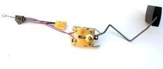
Appearance of the device
You should not ignore a breakdown of the fuel level sensor (FLS), because in the absence of information about the remaining amount of fuel, you run a high risk of not getting to the gas station, but stopping somewhere in the middle of nowhere.
Sensor Features
The VAZ fuel level sensor in most models has virtually no different design features.
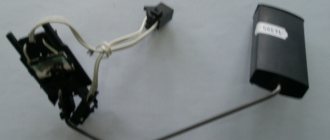
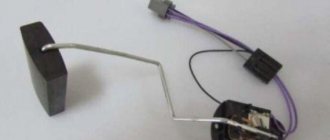
The FLS is a device with a float mounted in the gas tank of a car. Thanks to the position of the float, we get an idea of the amount of gasoline in stock - the lower it goes, the less the amount of fuel will be. The operating features of this device have minor differences depending on the type of engine. It doesn’t matter the carburetor or injector in your system - the principle of operation and location of the sensor remain the same. The measuring device, as mentioned earlier, is located in the tank, and can be accessed by tilting the rear passenger seat. This will come in handy if you need to check the sensor for functionality or replace it.
When it becomes necessary to check it:
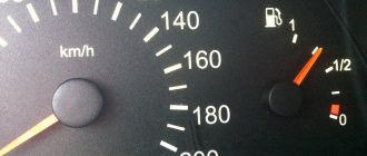
- The sensor does not show the gasoline level or is lying by several points. Sometimes the deviation from the truth is so great that it confuses the driver.
- The device arrow is frozen in one position or does not move from the Zero mark.
- Sometimes the opposite happens, when the arrow moves chaotically across the entire field.
DIY repair
If the sensor is equipped with a porous component, there are several options for changing it:
- You can remove it from the retainer socket and install a new one, securing it.
- Or replace the float itself along with the rod.
The second option is more preferable because it is easy to implement. If the surface of the strip on the rheostat scale is dirty, the element is cleaned.
The cleaning procedure is performed exclusively with cotton wool or a soft cloth pre-treated with alcohol. The use of harsh materials or other products is not permitted. This will damage the working layer of the scale; it is quite thin, so it can cause the rheostat to break. The element cannot be repaired; it will have to be replaced.
If the contacts of the electrical circuit come off the controller, they must be carefully soldered back or connected at the point of damage. Plates with mechanical damage (cracks, fractures) cannot be repaired, only replaced. If the sensor gives incorrect readings, the problem can be corrected by adjusting the angle on the so-called rod. This element is designed to fix the float. To get accurate readings, the angle is bent in different directions.
Gasoline sensor for VAZ 2109 (carburetor, injector)
If suddenly the fuel gauge needle drops down or behaves somewhat inappropriately, there is no need to worry too much. You can easily fix the problem yourself if it is a faulty sensor.
Appearance of the device
You should not ignore a breakdown of the fuel level sensor (FLS), because in the absence of information about the remaining amount of fuel, you run a high risk of not getting to the gas station, but stopping somewhere in the middle of nowhere.
Location
If usually most repair work related to the engine and its system is carried out through the engine compartment, then in the case of the fuel level sensor everything is somewhat different.
FLS location
Reasons for replacement
You will definitely have to replace the sensor if the car starts to produce the following:
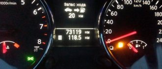
- The fuel level indicator needle “dances” or has fallen dead to the zero position;
- The indicator is constantly on, indicating a critical fuel level, although you have just filled the tank full.
FLS diagram
FLS on high and low panels
The differences in the sensors on the injectors and carburetors are minimal. Also, the fuel level sensors on VAZ 2109 cars equipped with a low and high panel are slightly different.
The difference lies in the resistance indicators. These parameters must be known when checking the condition of the sensor resistor.
Panel type
Resistance readings
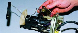
In this regard, when buying a new fuel level sensor, be sure to ask for a controller for a high or low panel, depending on what kind of car you have. It is also important to note that in the case of injection engines, the sensor is located inside the fuel pump, but it is based on the same operating principle as a carburetor one.
Functionality check
Do not rush to throw out the old sensor and replace it with a new regulator. First you can try to check if it really doesn't work.
To check, you will have to extract the “suspect” in any case.
- Inside the car, remove the lower part of the rear seat, remove the soundproofing material, if any. This will give you access to the inspection hatch in the floor of the car.
- Using a Phillips screwdriver, unscrew the four mounting screws that hold the hatch in place. Take it off. Under the hatch you will find a sealing gasket made of rubber. In any case, even if the old sensor works again for the benefit of your car, this gasket should be replaced.
- Disconnect the power supply block with wires from the sensor, and then unscrew the fastening nuts around the perimeter that hold the desired fuel level sensor on the tank body. Usually there are 6 of these nuts, and to dismantle them you will need an 8 socket socket or a regular wrench.
- Under one of the nuts there is a ground wire attached to a stud. Remove the wiring and put it aside for now. He shouldn't interfere.
- Carefully remove the sensor and do not forget to remove the rubber sealing gasket, which is located directly under the regulator. If there are signs of damage or defects on it, be sure to replace this component.
- When the sensor is removed, visually check its current condition. If there are mechanical damages, there is no point in further trying to repair it or restore its functionality. Change it right away.
- If there is no visual damage, check the condition of the float. It can be depressurized, that is, there is fuel inside it, cracks and various defects through which fuel has leaked are visible on the surface of the element. If all of this is present at the float, replace the entire sensor.
- Be sure to blow out the fuel filter with compressed air. A useful event that definitely will not harm your fuel system. Especially if the quality of gasoline with which you fill your VAZ 2109 leaves much to be desired.
- Check the condition of the resistor. To do this, you will need a multimeter in ohmmeter mode. Connect a measuring device to the sensor terminals and take readings. In the lowest position (empty tank), the resistance should be about 315-345 Ohms. If the tank is half full, the resistance will be 108-128 ohms. And when the tank is empty, the ohmmeter should show no more than 7 ohms. If the parameters differ from those specified, or there is no resistance at all, this indicates a malfunction of the controller. It must be replaced.
Removing and installing the carburetor
Installation and dismantling is carried out in case of repair of this unit, its complete replacement, as well as for thorough washing and cleaning. The AHU can become clogged if the car is driven on dusty roads, as well as as a result of untimely replacement of the air filter element.
Removing and installing a VAZ-2109 carburetor is very simple; even with the initial skills of a car mechanic, almost any driver (car owner) can do such work with his own hands. We perform the dismantling operation as follows:
- turn off the ignition, open the hood, remove the top cover, the filter element, then unscrew the four nuts securing the air filter housing (AFC);
- loosening the clamps, disconnect the fuel hoses, unscrew the two fastenings of the choke cable, move the cable to the side, disconnect the wire chips of the solenoid valve and the throttle valve closing sensor;
- We also disconnect the throttle cable, having previously removed the return spring, the ignition angle advance hose, and unscrew the nuts securing the carburetor itself (also 4 pieces);
- in order not to lose antifreeze and not to disconnect the coolant pipes, it is easier to unscrew the screw securing the heating unit, but it is located at the back of the housing, not in the most accessible place;
- in this case, lift up the unscrewed carburetor, move it forward, find a position in which it would be convenient to dismantle this fastener;
- Now nothing prevents you from removing the entire assembly.
If the KU is thoroughly stuck to the studs and does not pull off, you can gently tap it at the base with a small hammer and shake it with your hands from side to side. As a rule, after several attempts the device gives in; after removing it, you can begin further planned operations; installation of the unit is carried out in the reverse order.
Disassembly of the unit, its reassembly
To check the functionality of the VAZ 2108, VAZ 2109 sensor, it is necessary to disassemble the unit. You will need the following set of tools:
- screwdriver;
- key to 7;
- replaceable head for 10.
The following actions are performed sequentially:
- We recline the back seat and see the lid. Use a Phillips screwdriver to unscrew the fasteners and remove the compartment cover.
- There are a bunch of wires in the compartment, all of them must be carefully disconnected one by one so as not to damage them. This is where the 7 head comes in handy.
- Next, use a 10mm head to unscrew the fuel sensor itself, and then remove it from the gas tank. This should be done carefully, without jerking.
This completes all manipulations to disassemble the sensor assembly. Now the device can be cleaned, resistance checked or replaced. If there is external mechanical damage on the device body, you don’t even have to check it, but it is better to immediately replace it with a new one. The sensor cannot be repaired, just like its spare parts. Assembly is carried out in the reverse order, without any changes. Before connecting the wires, it is advisable to check their integrity. This is all that may be needed when dismantling the unit.
Tachometer troubleshooting
In order to restore the functionality of the VAZ 21099 tachometer in each specific case, it is not at all necessary to seek the help of professional auto mechanics. All that is required of you at this stage: a minimum of tools and the will to win.
So, the tachometer needle of the VAZ 21099 twitches. Diagnostics showed that the regulator relay unit is faulty. Its replacement is carried out as follows:
- the vehicle's mass is switched off;
- the wiring block in the rear cover of the generator is disconnected;
- the protective cap is removed along with the supply terminal;
- unscrews the relay regulator.
The installation sequence of a working voltage regulator is performed in reverse order.
How to troubleshoot speed indicator problems caused by replacing high-voltage wires? To do this, it is necessary to slightly supplement the tachometer connection diagram. Namely, a capacitor with a capacity of no more than 900 pF must be connected to the instrument cluster board. It will help reduce the nominal resistance of the external resistor, and will significantly improve the performance of the tachometer.
It is worth noting that this method is applicable only when the tachometer does not work on the injection model VAZ 21099, but not on the carburetor modification, the distinguishing feature of which is a high dashboard.
If, due to any circumstances, the tachometer needs to be replaced, when dismantling it, you must adhere to the following sequence of actions:
- de-energize the engine;
- remove the left segment of the torpedo;
- dismantle the protective glass, evenly pressing it away from the surface of the shield;
- remove the decorative strip;
- unscrew the wires from the terminals of the device;
- Unscrew the tachometer mounting screws.
When dismantling the tachometer, do not forget to be careful
In this case, it is important not to damage the integrity of the remaining measuring instruments: speedometer, fuel and temperature gauges
There is an opinion that a faulty tachometer should not cause concern and such a “trifle” will in no way affect the operation of the car. Still, you should not adhere to this position, because incorrect readings of this device may be the result of a breakdown of much more significant components of your car.
Operating principle of the fuel level sensor
Depending on the principle of operation of the sensors, the malfunctions that may occur with them will differ slightly. Let's look at the operating diagram of each type of fuel level sensor.
Float lever FLS
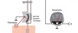
The operating principle of a float-type level sensor is based on the use of a rheostat. A lever is attached to its central part, at the end of which there is a float. Depending on the fuel level in the tank, the float will move, moving the rheostat lever accordingly along the contact path. During such movement, the resistance will change, which is recorded by the vehicle's electrical system. Accordingly, the arrow on the instrument panel will move in accordance with the indicated resistance on the rheostat. By the way, at a certain position of the float, and therefore the resistance value on the rheostat, a warning lamp on the dashboard will light up, indicating that there is little fuel left in the tank and refueling is necessary.
For clarity, let’s look at the operation of the fuel level sensor using the example of VAZ-2108/VAZ-2109, VAZ-21099 cars. Their design can use two sensors - for a high and low dashboard. They are structurally similar, but have different operating resistance. Specifically, for a high panel sensor, a resistance value between 238 and 262 ohms means the fuel tank is empty. With a resistance of 59...71 Ohms, the fuel gauge needle is approximately in the middle (accordingly, the tank is half full). If the resistance is within 17...23 Ohms, then this means that the car’s tank is completely filled.
As for the sensor for the low panel, the situation is similar. So, with a resistance of 285...335 Ohms, the arrow points to an empty tank. At 100...135 Ohms, the arrow will correspond to half, and at a value of 7...25 Ohms - at the end of the scale, pointing to a fully filled tank.
The specified resistances are important in the context of testing the sensor, since if it fails, the first thing to do is to check the internal resistance of the sensor using an electronic multimeter.
Please note that the indicated resistance values are relevant only for the listed VAZ models. For other machines, the corresponding values must be looked for additionally in the technical documentation (manual) attached to them. However, even these indicators can be used as a guide!
Tubular FLS
The design of the sensor is based on a housing with a guide post (actually a tube), at the other end of which there is a wire with a contact group (chip). The design also includes a float with slip rings located inside a hollow tube. The housing flange is secured using mounting bolts on the top wall of the fuel tank. By the way, this is a disadvantage of this type of sensor and imposes a limitation on its use. In particular, tubular type sensors can only be installed on tanks whose height is sufficiently large.
The operating algorithm of the tubular fuel level sensor is as follows:
- On the tube that touches the bottom, in its lower part, there is a hole (or two) through which fuel enters inside.
- The float located inside the tube has contact rings and when moving through the tube, as the fuel level in the tank changes, the resistance also changes. Resistance is measured using one or two contact wires located along the guide tube.
- The movement of the float on the surface of the fuel naturally changes the value of electrical resistance on the contact wire when power is applied to it.
- At the moment when the float is in the upper position (the tank is completely full), a small section of the contact wire is activated, and accordingly, the resistance value is minimal. At the moment when the tank is empty, the float is at the lower extreme point, respectively, the length of the signal wire is maximum, which also corresponds to the maximum electrical resistance.
The resistance of the fuel level sensor will differ for different cars, so when measuring you need to use technical documentation.
Electronic FLS
Electronic fuel level sensors are installed on cars that use high-quality gasoline and diesel fuel produced on a biological basis. This not only provides very accurate sensor readings, but also allows the actuator to “avoid touching” the fuel directly. However, the peculiarity of using such sensors is that it does not provide smooth monitoring of the fuel level (in small steps). The design of contactless FLS is based on an inactive magnetic sensor. The diagram of the fuel level sensor according to which it works is as follows:
- The main part of the sensor is located in a sealed housing. Only the magnetic sensor (MAPPS) and its lever are in contact with the fuel.
- The movement of the float with a magnet occurs along a sector defined by metal plates of different lengths. A signal corresponding to a certain fuel level in the tank is generated depending on the position of the magnet on a separate plate.
The fuel level indicator in this case is formed using a discrete method since the amplitude of the feedback signal will change from segment to segment that the magnet passes through. Depending on the model of a particular sensor, the signal amplitude and other technical information differ. The operating error of such a system does not exceed 0.5%...1%, but the cost is also significantly higher than a conventional contact system, so these FLS data are installed only on business and premium class cars.
What does the tachometer jump at high speeds indicate?
If the tachometer needle jumps during a trip or at high speeds, then the problem is also associated, as a rule, with the car’s engine. But before contacting a car mechanic, you can independently check the presence of fuel in the tank, inspect the camshaft drive chain, the timing belt that connects the crankshaft and the camshaft; perhaps it is loose and needs to be tightened. These are the main and frivolous reasons that can cause interruptions in engines and jumps in its speed.
If no visible problems are found with these elements, then you should go to an auto mechanic. Delay and failure to respond to a signal such as unstable tachograph operation can lead to serious damage to the vehicle’s cylinder-piston system and costly repairs.
It is better not to engage in diagnostics and independent repairs if the tachometer needle is floating. You should trust specialists who, using special equipment, will identify and eliminate the causes of the failure.
Greetings nivavoda! A problem arose - I start my Niva in the morning and start driving - at first everything is fine. Then once the revs drop right at speed and the car stalls. So five times. I start it up as if nothing had happened and it drives on, it also starts as usual with half a turn. Then I’m driving along the highway and I see the tachometer needle jumping from 0 to 6 thousand; in short, it’s showing nonsense. The engine is idling, the arrow jumps for 2 seconds and the car stalls. I looked at all the chips on the ignition, cleaned the contacts on the wires, cleaned the ground everywhere, it didn’t help. Ignition electronic carb. Tell me what this nonsense is!
Read more: Gle Mercedes Benz 2022 specifications
- Alekhandro_Goncharuk
- 26 September 2012, 09:04
- Alekhandro_Goncharuk
- September 26, 2012, 09:09
- v
- Jei_Shushunin
- September 27, 2012, 09:32
- v
- Makssh_Lukinih
- September 27, 2012, 10:12
- v
- Georgis_Grishnyakov
- September 27, 2012, 11:35
- v
- Sasha_Zyuzin
- September 28, 2012, 11:37
- v
Yes, if it were a contact one - if the arrow twitches - the conder is 100%
She doesn't suit you?? collapse branch
- Alekhandro_Goncharuk
- 28 September 2012, 13:08
- v
- Sergey_Komarov
- 28 September 2012, 13:09
- v
- Sasha_Zyuzin
- 29 September 2012, 13:18
- v
- Sergey_Komarov
- September 29, 2012, 14:00
- v
- Sasha_Zyuzin
- 29 September 2012, 14:10
- v
- Alekhandro_Goncharuk
- 29 September 2012, 17:20
- v
- Artur_Bibikov
- 30 September 2012, 14:04
- v
where can I even buy a switch??) for 21312, carb) only the tachometer is glitchy and most often when I’m driving in neutral or switching to a higher gear.. I think that’s the problem, and the car doesn’t even always start the first time, and even if it doesn’t start the first time then not with half a turn.. with half a turn the warmed one starts up smoothly.. I changed the spark plugs, changed the ignition wires, the weight is normal..
The problem is that I don’t know where to find a new switch or an internal analogue. collapse branch
| 120 posts on previous pages |
Reg.: 02/16/2008 Messages: 58 From: Belgorod Age: 32 Car: VAZ-21213.94.
I have the same problem: from the beginning the tachometer shows no signs of life, but after about forty minutes of driving it suddenly comes to life and works without interruption. The Hungarian gearbox is old, the ignition system is contactless, I bought the car recently.
Added after 4 minutes 51 seconds:
I checked the wire from the coil and even duplicated it, no damage is visible on the board, I rang all the described wires - no results
Reg.: 12/06/2004 Threads / Messages: 4031 / 23190 From: Moscow Age: 65 Car: 21214M, 2013
Alexey aka ALER.
Reg.: 12/04/2007 Messages: 76 From: St. Petersburg Age: 38 Car: VAZ 2121 89.
Reg.: 02/16/2008 Messages: 58 From: Belgorod Age: 32 Car: VAZ-21213.94.
Reg.: 05.25.2006 Threads / Messages: 11 / 1261 From: Moscow Age: 13 Car: 214, vw
Serge N
, thanks for the diagram!
and now the question is: why might the tachometer in the Hungarian panel not work? The resistors are soldered, there are no visible problems.. is there any way to check? or “no prospects, better buy a new gearbox”
Reg.: 12/06/2004 Threads / Messages: 4031 / 23190 From: Moscow Age: 65 Car: 21214M, 2013
Alexey aka ALER.
Reg.: 05.25.2006 Threads / Messages: 11 / 1261 From: Moscow Age: 13 Car: 214, vw
The printed circuit board of the tachometer itself is intact, without stains, without traces of corrosion, cracks, etc.
When the mechanism is removed, there are 2 sectors on the board with an angle of 90 degrees, and on the counter part of the device there are bent legs. these 2 sectors were scratched in one place, to the point of chipping the metal. I carefully filled it with solder and then sanded it. but this was the 2nd showdown today i.e. This is not the reason.
with a burnt-out 51 ohm resistor, what could go wrong? I'm a little far from electricity, so forgive my opuses
I'll try to measure the voltage tomorrow morning and report back
Useful for car enthusiasts - everything about cars
FLS installation process
FLS installation is carried out by partners in 100% of cases. Clients, as a rule, do not have the qualifications, experience and desire to install FLS on their own. The reasons for reluctance are not only technical, but also organizational and social (obstruction of innovations in control, sabotage and vandalism of drivers, etc.).
To install the FLS you must have:
- A team of 2 people (it is difficult for one person, for example, to dismantle the tank)
- Tools Bimetallic crown for metal (often with a diameter of 35mm)
- Angle drill
- Metal drills (often titanium nitride, yellow)
- Phillips and slotted screwdrivers
- Pliers (nippers, pliers, etc.)
- Hacksaw or pipe cutter
- Riveter (for securing the FLS to thick-walled tanks)
- Calibration equipment Calibration tube
As a rule, professional installers have a special technical vehicle. It contains tanks for draining fuel and a station for pumping fuel.
In addition to equipment, you need to have theoretical training and experience in solving non-standard situations.
Now let’s take a closer look at the installation process of each type of FLS.
Ultrasonic FLS
To install, you need to clean the area outside the bottom of the tank, glue the FLS there and secure it with a clamp placed around the tank. After this, the power supply is connected to the FLS and calibration is performed.
- The ultrasonic FLS is installed externally at the bottom of the fuel tank. For installation, the geometric center of the tank bottom is selected.
Operating time is approximately 4 hours.
Capacitive FLS
To install a capacitive FLS, you need to remove and evaporate the fuel tank, make a hole at the top of the tank, insert the measuring part of the FLS into it and secure the FLS with self-tapping screws to the surface of the tank. After this, the power supply is connected to the FLS, calibration and calibration are performed.
- Before installation, all fuel must be drained from the tank. Then you need to get rid of the fuel vapors remaining in the tank after draining the fuel. If this is not done, then when drilling a hole, an explosion will occur due to a spark (especially after using gasoline). To do this, the tank is dismantled, water is poured into it, drained (repeat), and then evaporated (the process is called “tank evaporation”).
- For installation, the geometric center of the tank is selected.
- A hole is made in the geometric center of the tank; metal shavings should not fall into the tank.
- The measuring part of the FLS is cut slightly shorter than the height of the tank - this way fuel can freely flow between the tank tubes. For trimming, use a pipe cutter or a hacksaw.
- Calibration in progress. This will allow the FLS to know its new length after trimming. To do this, the FLS is turned over with the measuring part up and completely filled with fuel. After 1-2 minutes, the fuel is drained.
- The capacitive FLS is installed in the hole made so that the measuring part is inside the tank, and the board with the interface cable is outside.
- The sensor is fixed to the surface of the tank with self-tapping screws. There are holes in the metal base of the top of the sensor on which the board is attached for self-tapping screws.
- The FLS is connected to the vehicle's on-board electrical network and to the computer. A special adapter is used for this. Software for setting up the FLS is installed on the computer.
- Calibration is in progress.
- The FLS is disconnected from the computer and connected to the tracker. Tracker installation is complete.
Operating time is approximately 4 hours. Training video from Omnicomm (10 minutes)
Connection to CAN bus
To connect to the CAN bus, you must first find it in the car. The CAN bus is two wires twisted into a twisted pair. There are many wires in a car, and there may be more than one CAN bus. Therefore, it is very difficult to find the right CAN bus without documentation about where it goes.
When it is found, a “CAN crocodile” is used to read the data (recommended) or connected directly to copper wires (less preferable).
Fuel injection system
For the new injection engine, an injection tank with a submersible pump was needed; I didn’t even consider the option with a remote Volgov pump, because my carburetor gas tank was already pretty tattered.
This is an old-style connector, similar to the lambda probe connector.
Also, as a bonus, I removed the fuel filter mount and the already rotted fuel lines and their fastenings to the body. The fastenings of injection lines differ from carburetor ones by the presence of an additional cell for the return line, which on injection cars is thicker than on carburetor cars.
The outside of the tank was cleaned of chips and rusty places, primed, and the entire tank was painted with Pfka.
When removing the module, it was discovered that the contact track on the FLS had been erased,
I revived it by soldering wire onto the end of the float
At first, the fuel pressure regulator was planned to be made from the GAZ 406 RTD of a new type, which gives a pressure of 3.8 bar because in the 124 engine the injectors are designed for exactly this pressure. This RTD was purchased, a thread was cut into its hole and an 8mm fitting was screwed onto the epoxy.
When I removed the module, I figured out the pinout of the connector, bought a lambda connector from my dad, and assembled the entire system for the battery test.
During the test, it turned out that the pump does not pump more than 3.4bar, the pressure in the “wall” with the return compressed is 4.4bar,
This pump could still work at a pressure of 3bar, but for a pressure of 3.8bar it is clearly not enough.
New details:
- weber pump
- Gas tank sensor 2110 DUT-1-01
- Gasket for fuel pump 2110, 2111, 2112
- Mesh filter 2110
- Fuel filter
- Fuel filter (injector) Tavria
- Fuel pipes 2109 1.5 l
- O-ring for fuel hoses 2110, 2111, 2112 BOSCH 30pcs
- Gas tank pipe 2108 BRT
Upon arrival of the parts, I replaced the pump, blower, mesh and tank o-ring
The pressure test with the new pump was successfully passed, 3.8bar, and when the hose was pinched, the pressure gauge went off scale and went to the second round. I pressed about 8-9bar into the “wall”. The gas tank was ready for installation.
I bought a 120g set of fuel lines at the market in Kharkov on the same day I bought the engine, but upon arrival I found out that instead of a supply + return set, they sold me two feeds on one of which “RETURN” was written in marker. At a local store I order an injection return for a VAZ 2109, they promise to deliver it in a week, but in the end a carburetor one arrives. On the site where I usually get spare parts there is no return line either. I search in all possible online stores, and here the most interesting thing begins on most sites as a sample return photo submission, I call to clarify whether the item in the photo is for sale, it’s also a PPC submission, and so on in every store.
As a result, I found a store that had a photo of the return line as an example, I called to clarify in detail, they even sent the photo to Viber, I made sure that it was exactly what I needed, it was sold as an original DAAZ for 230 UAH + 30 UAH in-time delivery. Well, now the whole set is available. While he was waiting, I removed the exhaust and the old lines, all the nuts were unscrewed normally, not a single stud was torn off, as usually happens. I oiled the niche until nothing was in the way; the brake pipes were quietly hanging in the air.
I removed the steering rack and laid new lines. Since there were no studs on the body for fastening the fuel filter bracket, and no welding to weld them, I hung it through the holes in the spare tire niche.
Everyone is here.
The left gas tank bracket fit from the carburetor, but the right one had to be lengthened, I cut out a metal plate of the required length and bolted it on.
The gas tank pipe is very sad
Installed a new one
When the tank was screwed into place, I decided that it would be a good idea to cut a technological hole to remove the fuel pump module without removing the tank from the car, because this procedure is very labor-intensive.
In order not to cut too much, I marked the boundaries of the module, and in order not to damage anything, I removed only the installed tank. I’ll tell you how I cut the hole for the module in the next post.
Dut vaz 2109 injector high panel
We present two diagrams for connecting the fuel level sensor of VAZ 2108, 2109, 21099 cars and their modifications with a carburetor engine.
Electrical diagram for connecting the fuel level sensor for VAZ 2108, 2109, 21099 cars with mounting block 17.3722 and a “low” instrument panel (before 1998 onwards)
Electrical diagram for connecting the fuel level sensor for VAZ 2108, 2109, 21099 cars with mounting block 2114 and a “high” instrument panel (after 1998 onwards)
Features of the fuel level sensor connection diagram
Notes and additions
— The fuel level sensor (FLS) of VAZ 2108, 2109, 21099 cars is installed in the gas tank on the fuel intake. It is a float rheostat that changes its resistance depending on the position of the float. Read more: “Fuel level sensor for VAZ 2108, 2109, 21099 cars.”
Appearance of the device
You should not ignore a breakdown of the fuel level sensor (FLS), because in the absence of information about the remaining amount of fuel, you run a high risk of not getting to the gas station, but stopping somewhere in the middle of nowhere.
Place 21093 in the AvtoVAZ model line
The prototype for the VAZ 21093 was the front-wheel drive hatchback VAZ 2109 “Sputnik”, with a 1.3 liter carburetor engine, produced in Togliatti since 1987. Its engine power was 64 horsepower. Externally, the 21093 Samara, which appeared in 1990, was not much different from the 2109. Dimensions, design, design - everything was almost like the nine. The main differences were hidden under the hood.
Modification 21093 received a new engine. The designers of the Volzhsky Automobile Plant increased the cylinder diameter from 78 to 82 mm with the previous piston stroke of 71 mm. This resulted in an increase in the working volume from 1288 cubic cm to 1499. The car's power increased, its performance characteristics improved (speed and acceleration dynamics), and fuel consumption decreased slightly. In general, the VAZ 21093 car has acquired noticeable liveliness.
Fuel level sensors VAZ 2101-2107
The period of development of high technologies affected almost all areas of human activity, including the automotive industry. Carburetor engines are being replaced by so-called injection engines, the operation of which is controlled by various types of sensors. Modern cars with injection control systems contain a large number of them.
This article will focus on one of these sensors, namely the fuel level sensor (FLS). For car enthusiasts interested in this device, I will try to briefly outline the answers to questions such as:
- Features of the FLS device.
- Principle of operation.
- Main signs of a malfunction.
- Is it possible to repair the FLS?
The sensor is located directly in the car's gas tank. Let's look at what elements the FLS consists of on most Lada cars. The sensor is attached to the base of the fuel pump and consists of the following elements:
- a reading device with a float connected to it;
- connectors for power supply and connection to the fuel pump.
The idea of work is to correspond the level of gasoline in the tank to a certain sensor signal. By measuring the fuel level, the sensor transmits data to the car's dashboard. There are several options for such sensors, but their purpose is the same. The main signs of failure of the FLS are: the arrow on the instrument panel constantly moves; when the tank is fully filled, the arrow is in the zero position; Regardless of the fuel level, it does not move at all. Before replacing the sensor, you should check the fuse responsible for its operation and the wires for breaks.
The FLS is a fairly reliable device and lasts a long time. Of course, repairing this sensor is possible, but it is not a fact that after repair it will serve you for a long time. Given its difficult-to-reach location, I consider it advisable to replace the sensor with a new one so that it does not take up your time and effort in the future. The cost of a sensor for domestic cars currently fluctuates around 400-450 rubles.
In conclusion, I would like to warn car owners against the occurrence of unforeseen situations associated with the failure of any elements of the vehicle’s electrical equipment. When replacing various electrical devices, be it sensors or lighting bulbs, for complete safety, I advise you to disconnect the terminals from the car battery.
I hope after reading this article you have received a sufficient amount of information about how the fuel level sensor works and the principles of its operation.
Idle speed adjustment
The second setting of the VAZ-2109 carburetor is idle speed, it can be partial or full. The first is for minor speed adjustments, the second is for adjusting the amount of air (setting CO emissions in the exhaust gases).
Partial adjustment is performed using the air-fuel mixture “amount” screw. This screw sets the opening angle of the throttle valves, which ensures that the air-fuel mixture enters the cylinders when the accelerator pedal is released. The “quantity” screw rests on the throttle valve control lever and when screwed in, it pushes the lever, causing the valves to open slightly.
Partial idle adjustment is performed with a warm engine and creating a load on the vehicle's on-board network by turning on the high beam headlights and the interior heater at full power. The adjustment is carried out with the engine running by screwing in/unscrewing the “quantity” screw until the optimal idle speed is established, which for the VAZ-2109 is 800-900 rpm (this can be tracked using a standard or plug-in tachometer).
If it is not possible to set the required speed or the motor operates unstably at it, a complete adjustment is made, which is made by two screws - “quantity” and “quality”.
The algorithm for this adjustment consists of the following stages:
- Warm up the engine and then turn it off;
- We find the quality screw (it may be closed with a plug that will have to be removed), screw it in until it stops, and then unscrew it 3-4 full turns;
- We start the engine, turn on electrical consumers (lighting and stove) to create a load in the on-board network;
- By rotating the “quantity” screw, we achieve 700-800 rpm on the tachometer;
- By turning the “quality” screw, we set the maximum possible speed (they will increase to a certain level, and then stop. The moment the speed increase stops is considered the maximum);
- We set the “quantity” screw to 900 rpm;
- Using the “quality” screw we lower them to 800 rpm;
- We slowly tighten the “quality” screw until interruptions appear in the operation of the power plant, after which we unscrew it back 1 turn;
- We adjust the speed with the “quantity” screw, bringing it to a normal value - 800-900 rpm;
After the adjustment operations, we check that they were carried out correctly. This is done by sharply pressing the gas pedal and then quickly releasing it. With a properly configured carburetor, the engine should respond quickly to pressure, without any failures or hesitations. And after releasing the pedal, the speed will drop to the idle level, without sags or instability of the engine.
Signs of trouble
FLS failure does not happen often, but at some point it can take the driver by surprise. Incorrect gasoline readings can result in the car owner overfilling the car tank at a gas station or running dry on the road.
Although a breakdown is a rare occurrence for this device, it becomes immediately noticeable to the car owner. The appearance of problems with FLS manifests itself in a car as follows:
- The arrow, which shows the amount of gasoline in the gas tank, constantly remains at zero, even when refueling the car;
- The arrow indicates overestimated indicators. For example, a full tank is shown when it is only half full;
- The arrow indicates underestimated indicators. For example, when filling a full tank, the dashboard displays much less.
It is not necessary to get a new device if these problems arise. In some cases, it is possible to adjust it and resolve inaccuracies.
Functionality check
The VAZ 2109 fuel sensor can be checked for functionality using an ohmmeter or multimeter. After the device is removed from the gas tank, its contacts should be connected to the tester. We fix the float in one position and look at the indicators. The result should be 275-320 Ohms in the upper position of the float or 5-20 Ohms in the lower position. In the middle the resistance indicator is 100-130 Ohms. These figures are for a low instrument panel.
For a high panel these values are different:
- 260-280 Ohms in the lower position;
- 60-70 Ohm - average value;
- 15-20 Ohm is the upper limit position of the float.
If the device’s performance corresponds to the examples given, the device is working, everything is in order with the sensor, and it does not need repair or replacement. When significant deviations are present, it is worth checking the integrity of the wires. If they are ok, the sensor itself is faulty and needs to be replaced.
The FLS is working properly. What to do?
Try the following activities.
- The sensor connector has a pair of wires - pink and blue;
- The pink one controls the arrow of the fuel level indicator in the tank, and the blue one is responsible for the critically low fuel level indicator;
- Take any jumper at hand, that is, a piece of any wire, and then use the jumper to short the pink wire to ground, while turning on the ignition. At this moment the arrow should be in the full tank position;
- Now, similarly, using a jumper, we connect the blue wire to ground. This should turn on a light that indicates on the dashboard that the fuel level inside the gas tank is low;
- If, when the jumper is shorted to ground, the indicator or lamp does not work, this indicates that the indicator itself is “covered”, or there is a problem with the condition of the wiring.
There is absolutely nothing complicated about replacing the sensor. Dismantling work can be completed in 30-60 minutes with even a little experience. As for the FLS itself, it does not fail very often, but every owner of a VAZ 2109 and more should know about the features of its replacement.
Why doesn't the starter turn or click?
The absence of starter rotation is possible together with the absence of a relay activation mechanism. If the relay is working properly, a click is heard, if not, there are no sounds when you turn the ignition key.
Experts note the following main reasons why the starter does not turn or click on the VAZ-2109:
- the tip has come off the wire connected to the terminal and located on the retractor relay;
- there is no charge on the battery;
- the terminals from the battery have oxidized;
- the mechanism relay is damaged, for example, the terminals are oxidized or a break appears;
- the wiring in the contact component of the ignition switch is disconnected (how can you accurately identify these wires? They are colored pink and red);
- The solenoid relay does not work correctly, it may become jammed, or the device has warmed up and now needs to be replaced.
Replacing the fuel level sensor on a VAZ 2108, VAZ 2109, VAZ 21099
Welcome! Today we will discuss in detail the replacement of the fuel level sensor in the tank. The entire replacement process will be supported by pictures for your convenience, and at the very end of the article you can see a video that will describe in detail the replacement of the sensor and its configuration.
Note! The replacement process, as you have already seen from the title of this entry, will take place on cars of the “Samara” family!
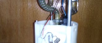
Where is the fuel level sensor located? Its location is very simple, and all because it is located in the floor of the car body under the rear seat. But in order to get to it, you will first need to lift the rear seat cushion and after that, lifting up the noise-insulating material, you will be able to see the fuel level sensor installed in the floor of the car.
Note! In the photo above, the arrow indicates where this sensor is located, but as you can see in the photo, it is invisible, and all because the noise-insulating material is not bent back!
When do you need to change the fuel level sensor? It must be replaced with a new one if:
• Incorrect operation of the fuel level arrow, which is shown in the bottom photo. For example, if the sensor fails, the fuel level needle may begin to work incorrectly or may even stop showing the state of gasoline in the tank.
Major damage to the gas tank
When using a fuel tank for a long time, situations arise that require repair. First of all this:
- holes and cracks resulting from mechanical stress and corrosion;
- clogging of pipes and hoses directly connected to the tank;
- damage to the connecting seam at the junction of the tank halves.
Small cracks are usually sealed. This is a rather labor-intensive procedure, but the functionality of the tank can be completely restored. In case of major damage or holes, the tank is replaced with a new one. Dirt gets into the hoses along with low-quality fuel. In this case, the mesh through which gasoline enters the tank may become clogged. Therefore, it must be periodically washed and changed. In addition, you should only refuel at proven gas stations and do not abuse additives to reduce fuel consumption. The weakest point of the tank is the seam, which is constantly subjected to severe stress. This can be avoided if the tank is made in one piece. The fuel tank can also fail due to deformation of the neck, formation of dents after an accident, separation of partitions inside the tank, etc.
Fuel level sensor (FLS) for VAZ 2108, 2109, 21099 cars
In the power supply system of the carburetor engine of VAZ 2108, 2109, 21099 cars, a fuel level sensor (FLS) is installed, designed to monitor the amount of gasoline in the fuel tank. It is located on the fuel intake in the vehicle's fuel tank. On the instrument panel there is a fuel level indicator and a fuel reserve lamp (indicator), connected by an electrical circuit to the fuel level sensor and transmitting information from it directly to the driver. The fuel level sensor (FLS) has a round flange that is attached directly to the fuel tank. On the flange there is a sensor connection block with two terminals. A fuel intake pipe and a return pipe are welded to it. The sensor itself has a plastic housing mounted on a support plate. Inside the housing there is a rheostat with a winding of nichrome wire and a fixed contact for turning on the fuel reserve lamp. The contact is connected to the sensor block (terminal “W”). The rheostat has a slider mounted on a rotating axis and connected to a movable lever, at the end of which a sealed plastic float is installed. The lower end of the rheostat is connected to the sensor block.
The principle of operation of the fuel level sensor for VAZ 2108, 2109, 21099 cars
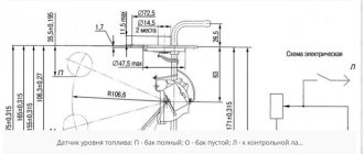
The float moves down or up when the fuel level in the gas tank drops or increases. At the same time, the slider connected to it moves along the rheostat winding, changing the resistance at the output of the rheostat from low to high and back. A drop and increase in resistance is reflected in the movement of the needle on the fuel level indicator in the instrument panel. The level in the tank is low, the float is lowered - resistance is 285-335 Ohms (the fuel level indicator arrow is at zero), the indicator arrow shows the tank half - resistance is 100-135 Ohms, the tank is full (the arrow is all the way to the right, the float is raised) - 7-25 Ohms .
In the lower position of the float, when the fuel level is at its lowest (4-7 l), the contacts on the slider and the contact of the fuel reserve lamp close. The lamp on the instrument panel lights up.
operation of the fuel level sensor (FLS) with a full tank: the float has floated up, the slider contact at the bottom of the rheostat (minimum resistance), the moving and fixed contacts of the fuel reserve indicator lamp are open (the lamp does not light up)
operation of the fuel level sensor when the fuel level in the fuel tank of a car drops: the float fell, the slider contact moved up the rheostat winding (maximum resistance), the moving and fixed contacts of the fuel reserve lamp closed (the lamp lit up)
Electrical diagram of connections of the fuel level sensor for VAZ 2108, 2109, 21099 cars
Electrical diagrams for connecting the fuel level sensor on VAZ 2108, 2109, 21099 cars with a “low” and “high” instrument panel are presented on the page “Connection diagram for the fuel level sensor on VAZ 2108, 2109, 21099 cars.” Applicability of the fuel level sensor on VAZ 2108, 2109, 21099 cars
On VAZ 2108, 2109, 21099 cars and their modifications, fuel level sensor 24.3827 and its variants are used. Its characteristics are as follows: voltage -12 V, rheostat impedance - 350 Ohm, float lever length - 115 mm, lever angle when the tank is empty - 27.5 degrees.
Causes of errors
The main reason why the fuel level may be displayed incorrectly on the instrument panel is long-term operation of the sensor.
Most often, the device is replaced with a similar one from another car model, for example, VAZ 21099, 2110. After the replacement, some drivers notice that the data is displayed incorrectly. Most often this happens if the sensor was removed from an earlier version of the car and installed on a later one, for example, from 2109 to 2110 model. In addition, incorrect data may also appear after installing the Europanel.
The reason may be in the contacts, but there is no exact solution, so if you want to change the sensor, then look for a similar model.
Another reason is a littered float. When this part of the device is left in gasoline for a long time without cleaning, it can become covered with a rather unpleasant coating. As a result, the structure becomes heavier, which leads to constantly overestimated performance, as well as to rapid breakdown of the lever and float. The float can be replaced, but only with exactly the same one, not a similar one.
Location
If usually most repair work related to the engine and its system is carried out through the engine compartment, then in the case of the fuel level sensor everything is somewhat different.
The FLS is located under the rear seat. To access it, you need to remove the seat, bend back the soundproofing material, if any, and find the controller we need in the area above the fuel tank.
FLS location
Purchasing new equipment
Repairing old equipment is not difficult if it has become unusable due to oxidation or rust formation. Wiping the device can help restore contacts, but if the device is broken, even after restoration it may display incorrect data. If the error is more than 10%, then this can significantly affect the driver’s comfort behind the wheel, as well as the risk of being left with an empty tank on the road.
Therefore, if there is an error, it is recommended to replace it with a new device. Thus, the car owner can be confident in the accuracy of the data displayed on the dashboard. The cost of spare parts is relatively inexpensive; an injector can be found within 300 rubles. The part is easy to maintain and does not require replacement often, so it is recommended that if the data is inaccurate, replace it immediately.
Purchasing new equipment ensures that correct readings are displayed. By purchasing original spare parts, the car owner can forget about replacing them within 2-3 years.
Sources
- https://artel55.ru/diagnostika-i-remont/zamena-datchika-urovnya-topliva-vaz-2109.html
- https://k-SportRacing.ru/neispravnosti-i-remont/ne-pokazyvaet-uroven-topliva-vaz-2109-inzhektor.html
- https://adm-maisk.ru/shumoizolyaciya/dut-vaz-2109-inzhektor.html
- https://moto163.ru/tyuning-i-servis/datchik-topliva-vaz-2109-inzhektor.html
- https://lemzspb.ru/provod-dut-vaz-2109/
- https://RetroTruck.ru/obsledovanie-i-remont/nepravilno-pokazyvaet-uroven-topliva-vaz-2109.html
- https://luxvaz.ru/vaz-2109/356-datchik-benzina-karbyurator-i-inzhektor.html
- https://7road.ru/drugoe/datchik-urovnya-topliva-vaz-21099.html
- https://ladafakt.ru/datchik-urovnya-topliva-vaz-2109-inzhektor.html
- https://linhai-russia.ru/remont/datchik-topliva-vaz-2109-inzhektor-2.html
- https://toyota-chr2.ru/polomki-i-remont/zamena-datchika-urovnya-topliva-vaz-2109-karbyurator.html
[collapse]