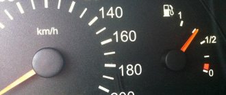
As you know, the FLS (fuel level sensor in the tank) is an important element in the design of the fuel system of a car. It is quite obvious that if the gauge does not show the fuel level on the dashboard or does not show the fuel level correctly, difficulties arise during the operation of the vehicle.
In such a situation, the driver is inevitably faced with the fact that it is not possible to accurately determine the level in the tank, it is difficult to calculate when it is necessary to refuel, calculate fuel consumption, etc. Next, we will look at why the fuel sensor does not show correctly or the fuel level indicator in the fuel tank does not work, as well as how to eliminate such malfunctions.
Features of the device and operating principle of the fuel sensor
Modern fuel level sensors in the tank are divided into 3 types:
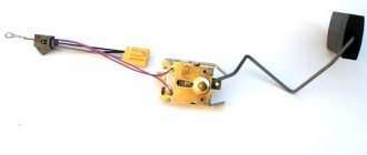
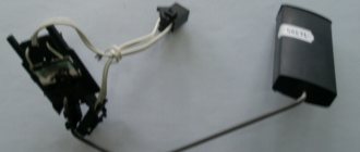
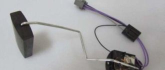
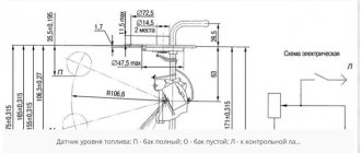
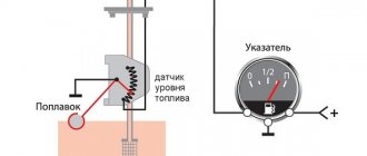
- FLS lever type. The sensor is based on a resistor with a movable tap contact. Depending on the position of the slider on the resistive track, the resistance in the fuel level sensor circuit changes. To display readings on the dashboard, it is not the resistance of the resistive section itself that is important, but the voltage drop that occurs in the section with changing resistance. The potentiometer slider is connected through a metal rod to a float, which is always located on the surface of the fuel poured into the tank.
- Tubular type sensor. The float moves inside the tube along a guide post. Inside the float there is a pair of interconnected contacts through which resistance wires pass. One of the pins is supplied with a reference voltage, the second pin is a signal one. The more fuel in the tank, the higher the float is and the greater the resistance in the circuit;
- FLS of non-contact type. The float is connected through a lever to a magnetic sensing element. Changing the position of the magnet relative to metal plates of different lengths generates a certain electrical signal. By digitizing the analog signal from the sensor, the control unit displays the level of gasoline/diesel on the dashboard.
The advantage of a magnetic position sensor is that the sensing element is located in a sealed housing and does not come into contact with the fuel in the tank. Despite its versatility, MAPPS is widely used only on cars running on biodiesel, methanol and ethanol. New types of fuel do not allow the use of contact-type meters due to the high aggressiveness of the environment to open conductive elements.
Troubleshooting
Now you need to understand why the fuel level sensor does not work on your car and how to do it correctly.
You should always start by checking the power supply to the controller through the installed fuse. If there are problems with open access to the device in a particular vehicle, then use the electrical diagram. The tester leads are connected to the corresponding connectors of the blocks. To do this, take pieces of wire.
If access is open, then the chip is disconnected from the sensor and diagnostics are carried out using a conventional multimeter or tester. Usually, to get to the FLS, you need to climb into it through the luggage compartment, or remove the rear row seat in the car.
Now let’s talk about how to properly check the fuel level sensor in your car. It is important to understand which contacts the connection is being made to. To do this, you can’t do without a wiring diagram. But owners of cars with a conventional resistive controller are in luck. Here, look at the cross-sectional dimensions of the wires used, going directly to the block. The fuel pump always has a thicker wire than the sensor.
Reasons for incorrect readings
- Formation of oxides and dirt deposits on the surface of the resistive layer. Deposits disrupt the contact patch between the slider and the conductive layer, which increases the resistance in the circuit. Both lever and tubular FLS systems are susceptible to malfunctions.
If the car is most often used with a half-empty tank, there is a high probability that after filling the tank full, the fuel gauge will begin to lie or will not show the amount of fuel at all. The less often the slider moves along a certain zone of the resistive track, the higher the likelihood of parasitic resistance forming on it.
- Breakage of the resistive layer. Constant movement of the slider leads to abrasion of the contact track. The malfunction is typical for cars with high mileage and most often occurs on gasoline engines. The lubricity of diesel fuel is higher, which reduces friction between the slider and the contact track. The failure is typical only for the lever-type fuel level sensor.
- Mechanical faults of the fuel sensor. Most often they occur due to careless removal or installation of the fuel module. If the fuel gauge does not read correctly after repair, it is likely that the float mounting arm is bent. A broken lever mounting axis completely disables the meter. There are cases when, due to a manufacturing defect, the seal of the float is broken, gasoline is collected inside it, as a result of which the indicator on the dashboard always shows an empty tank.
- Electrical circuit malfunction. For the sensor to operate, it requires a reference voltage and a whole signal output circuit from the meter to the instrument panel. The fuel sensor may lie and not show the fuel level in the tank due to oxides inside the connecting blocks and frayed wires.
- Malfunction of the fuel level indicator. If the electrical circuit is intact and the FLS is in good working order, the only thing left to blame is the indicator. Often the cause of the malfunction is poor contact where microelements are installed on the circuit board. Constant temperature changes and poor quality control in the manufacture of signs for individual car models lead to cracks in soldering.
How to organize GPS GLONASS fuel consumption monitoring
To organize an effective fuel control system, a vehicle monitoring program is installed in the company’s office, for example, the “1C: GLONASS/GPS Satellite Monitoring Center” solution, and vehicles are equipped with GPS GLONASS trackers. For the most accurate assessment of actual fuel consumption, it is recommended to additionally install fuel level sensors on vehicles. Methods for organizing control of fuels and lubricants:
Calculation method based on fuel consumption standards
- The GPS monitoring system records fuel consumption standards,
- From car trackers, the monitoring system receives data on the actual mileage of the vehicle,
- The system automatically calculates fuel consumption, multiplying the standard indicators for fuel consumption per 1 km. on mileage data for a certain period.
In this case, data on the mileage and movement of each vehicle is displayed on an electronic map, and the dispatcher can assess the validity of fuel consumption by comparing the actual movements of vehicles with the planned routes.
- low cost,
- there is no need to equip the fuel system with additional devices,
- the information obtained is more accurate than when calculated using odometer data.
- calculated figures may differ significantly from actual ones,
- There is no way to track drains and refills.
Standard sensors for monitoring fuel consumption
A standard sensor is most often a float sensor that is installed at the factory when the vehicle is released. The position of the float changes with any change in the fuel level in the tank. The sensor signal is received by the vehicle's dashboard. A GPS tracker can be connected to a standard sensor in two ways:
- Directly through the analog input of the GPS tracker, after which the sensor is calibrated,
- Via the CAN bus, in this case the tank filling data is read from the CAN bus and there is no need to calibrate the sensor.
In this case, data on the mileage and movement of each vehicle is displayed on an electronic map, and the dispatcher can assess the validity of fuel consumption by comparing the actual movements of vehicles with the planned routes.
- low cost,
- allows you to record both consumption and fuel filling and draining,
- no need to install additional equipment.
- low data accuracy. The readings may be significantly distorted depending on the nature of the movement (hill climbs, acceleration and braking),
- the range of sensor readings contains “dead zones”: 10-15% of the upper and 5-10% of the lower volume of the tank.
Submersible fuel level sensor
How it works:
- The sensor is placed in the car's gas tank so that the measuring tube is immersed in the fuel. Next, the sensor is connected to the GPS GLONASS tracker,
- The tank is calibrated, calibration points are recorded in the GPS fuel consumption monitoring system,
- The data is transmitted online to the GPS monitoring system, where it is transformed into indicators of the level of fuel and lubricants. Based on this data, the system records consumption, as well as drains and refills.
- High data accuracy,
- Suitable for any cars.
Installation of the sensor requires the assistance of a specialist.
Flow-through fuel flow sensor
How it works:
The sensor is mounted in the fuel line. Consumption indicators are determined based on measuring the volume of fuel passed through the fuel sensor.
- Maximum data accuracy,
- Suitable for any cars.
- Requires specialist assistance in installation,
- The sensor only monitors actual fuel consumption; there is no way to record refills and drains.
Connecting a GPS tracker to a car's CAN bus
CAN (Controller Area Network) is an industrial network standard aimed at combining various actuators and sensors into a single network.
All high-tech systems of a modern car use the CAN protocol for communication. The diagnostic connector also usually contains an output from the vehicle’s CAN bus.
We use the CAN bus to obtain satellite monitoring parameters such as:
- Fuel level
- Fuel consumption
- Engine running time
- Total mileage
- Gas pedal position
- Axle load
- Engine speed
- And many others
How to check the fuel level sensor?
You should start diagnosing by studying the electrical diagram of the FLS connection on your car. With the ignition on, check at the fuel module connector for the presence of supply voltage to the gasoline level meter. To do this, use a multimeter in DC measurement mode or a test lamp to check electrical circuits. The presence of a construction resistor, which allows you to manually change the resistance of the circuit, will facilitate diagnostics. This way you can simulate a normally working fuel level sensor by checking the integrity of the wires from the gas tank to the dashboard and even the serviceability of the indicator.
If to remove the fuel module it is necessary to dismantle the fuel tank, it makes sense to test the circuit from the FLS to the instrument panel for a break or parasitic resistance. Confidence in a working signal circuit will increase the chance that the reason why the fuel sensor does not work lies in the tank and the labor-intensive process of dismantling it will not be in vain.
After removing the fuel module, inspect the sensor components for mechanical damage and characteristic malfunctions of potentiometric position sensors. Oxides and plaque can be removed with a cotton swab dipped in solvent. Be careful when cleaning the resistive layer with abrasive elements (hard sponge, Scotch Brite, sandpaper) so as not to damage the conductive layer. If the contact tracks are damaged, the gasoline sensor will have to be replaced with a new one.
Removing the sensor
Depending on the vehicle model, the process for removing the device may vary slightly. In any case, certain points are similar. Here are the main steps to remove a failed sensor:
- Initially, the negative terminal from the vehicle battery is reset.
- Provides access to the sensor. To do this, you need to remove the upholstery in the trunk. In some cases, it will be necessary to remove one of the rear seats.
- All sensors are equipped with a special fixing safety plate. To remove it, you need to unscrew the mounting bolts.
- It is imperative to clean the sensor from dust and dirt if you plan to use it again after repair.
- All mounting bolts and wires are removed from the device.
After completing all the described manipulations, the device can be removed. This process must be performed carefully so that its structure is not damaged.
Dependence of the signal shape on the type of indicator on the dashboard
The in-tank meter has no electronic components and sends an analog signal to the instrument panel. There are 2 types of signs installed on passenger cars:
- analog fuel level indicator (UUT) - indicators based on a bimmetallic plate. From the sensor in the tank, current flows to the plate, which, when heated, deforms, shifting the indicator arrow attached to the axis. The higher the current in the circuit, the greater the distance the arrow on the dashboard deviates. Often, the gasoline sensor incorrectly displays the fuel level due to fatigue deformation of the bimmetal plate or breakage of the arrow mounting axis;
- digital UUT. To operate a control unit of this type, a converter installed in the dashboard is required. It modifies the analog signal from the sensor into a pulse that is “understandable” for the pointer. Such sensors do not have inertia in readings and very rarely fail due to malfunction of electronic components due to cracks in the places where elements are soldered to the board.
When to make adjustments
The first calibration of the gas level indicator is carried out at the time of installation of gas equipment on the car. But over time, the indication on the button may become confused or may not be initially configured correctly. Thus, if the arrow on the gas cylinder shows one value, and the indication on the button is completely different, you cannot do without adjusting the gas level sensor.
You can entrust the procedure to professionals, but why pay a lot of money for something that you can do yourself?
First of all, you should understand whether the gas level indicator showed the correct value before? If not, then it will take a little more time and a special HBO cable to connect the electronic control unit to the laptop and set the correct value for the gas level sensor.
For each sensor in the control unit, you must set its own value. You should also know what kind of sensor is installed in your system and according to what scheme it works - it measures resistance or measures voltage. Having set the necessary sensor parameters, you should proceed to the calibration itself.
FLS fuse
Sudden sensor failure suggests a blown fuse. But the on-board network of a modern car does not provide a separate fuse to protect the fuel supply circuit of the FLS. Everywhere, the indicator and meter circuit is part of a whole group of sensors and actuators, protected by a common fuse for the instrument panel. Therefore, in the event of a short circuit in the sensor circuit, the fuse-link of the instrument panel burns out.
Replacing the FLS on a VAZ-2114
Even a novice driver can repair the sensor with his own hands. Of course, the breakdown should not be serious, so replacing a failed element will not be difficult and will not take much time. For example, if a float breaks, you can always buy a new one on the automobile market. The old float is easily removed from the holder, and a new one is installed in its place.
Even oxidized threads are often replaced with new ones if they cannot be torn off. The price of a new sensor is relatively low, so very often drivers simply prefer to buy a new mechanism.
The process of replacing the FLS on a VAZ-2114 includes the following procedure:
- Disassemble the lower part of the rear seat and remove the trim, since the sensor is a structural part of the fuel pump. You cannot access the mechanism without filling out the form.
- Using a 7 mm wrench, unscrew the two screws that secure the gas tank cap.
- Then you need to unscrew eight more screws that secure the edge of the lid.
- After these steps, the cover can be easily moved forward.
When access to the fuel pump is ensured, it is necessary to remove part of the lock cable. Don't forget to unscrew the nuts securing the fishing line. Before the cap is fully opened, it must be turned once to relieve pressure in the system.
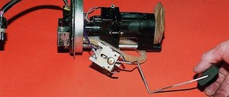
You need to release the fuel pump carefully and carefully, so as not to damage the float, you must first lift it, then turn it clockwise and tilt it. Once you have the fuel pump in your hands, you can start looking for the sensor itself.
The procedure is as follows:
- disable the lock;
- remove the sensor terminals and unhook the fasteners from the cover;
- remove the module cover;
- use a screwdriver to move the retaining ring;
- release the fuel sensor clamps and disassemble the mechanism.
This completes the work of replacing the sensor. You need to install the new mechanism in place and reassemble the module in reverse order. As you can see, there is nothing complicated in carrying out this work, you just need to arm yourself with the necessary equipment - screwdrivers and a set of keys.