The VAZ 2112 temperature sensor not only allows you to monitor the condition of the engine and coolant. The data obtained from it allows you to regulate the amount of fuel supplied to the combustion chamber.
It is necessary to check the condition of the sensor, and if it breaks down, replace it immediately.
What functions does the sensor perform?
This device performs a lot of tasks. Based on its readings, the fuel mixture is prepared and the ignition timing is changed. The element also gives commands to turn on the fan in case of overheating.
Enrichment of the mixture is always associated with increased temperatures in the power plant. The lower the engine temperature, the richer the mixture needs to be fed into it. Any electronic control unit works on this principle. And the domestic top ten is no exception.
Malfunctions of the idle air regulator and its check
In cars equipped with an injector, a separate actuator (IAC), controlled by a controller, is responsible for engine idle speed and cold start.
Although its design is simple and reliable, during the operation of the car the element may not work correctly or, like any other part, fail due to natural wear and tear.
How to identify symptoms of a malfunction and check the idle air control in a garage is described in detail in this publication.
How does the regulator work?
In everyday life, the IAC is often called a sensor, although in reality it is not one. The element is a stepper motor housed inside a non-separable housing. Only the spring-loaded rod with a cone-shaped tip protrudes outward. At the command of the ECU, the engine extends or retracts the rod to a certain distance.
The idle speed sensor is located in the throttle valve block, the working cone is extended into a small cross-section bypass channel.
Since the engine starts and idles without pressing the accelerator pedal, the mentioned channel supplies air to the cylinders when the throttle is closed.
The task of the IAC is to regulate the amount of air flow, blocking part of the flow area with a cone.
- After the driver turns on the ignition, the controller activates the governor motor, forcing the idle air passage to open. The ECU calculates the opening amount using a temperature sensor - if the engine is cold, the rod will move back more.
- At the moment of startup, the injectors supply an enriched mixture to the cylinders. Then the amount of fuel is reduced so that the engine does not “suffocate” and stall. The speed is monitored by the control unit using a crankshaft position sensor.
- The volume of air entering through the IAC is taken into account by the mass air flow sensor located on the inlet pipe, while increased crankshaft speeds are maintained (1200–1500 rpm).
- Using the temperature sensor, the control unit “sees” that the engine is warming up and gradually reduces idle speed, giving the command to the IAC to cover the cross-section of the bypass channel. When the temperature reaches an acceptable value (60 °C or more), the regulator maintains the speed at 850 rpm.
Note. If a warm engine is started, the controller immediately sets the IAC rod to the operating position corresponding to normal idle speed.
Symptoms and causes of IAC malfunction
Signs of a malfunctioning idle speed sensor appear as follows:
- during a cold start, the crankshaft speed does not increase, which is why the engine runs unstable and tends to stall;
- there is a drop in the number of idle revolutions after a significant increase in the load on the generator - turning on headlights, electric heaters, and so on;
- the engine periodically stalls when any gear of the manual transmission is switched off (the symptom manifests itself while driving);
- The speed “floats” - it spontaneously increases and decreases.
Important point! There is a misconception that a regulator failure is necessarily accompanied by the inclusion of the Check Engine indicator on the dashboard. Since the element is an actuator, the light warning option is not provided in all cars.
If the car shows signs of IAC malfunction in the form of floating engine speed at idle, advanced diagnostics may be needed.
A spontaneous change in the crankshaft rotation speed occurs for many reasons - failure of a sensor, air leaks, gas distribution malfunctions, and so on.
It is better to start troubleshooting by checking the regulator.
IAC failure occurs for three main reasons:
- Open or poor contact in the power supply circuit. Simply put, there are problems with the wiring.
- Breakdown of the stepper motor due to natural wear and tear. In this case, only replacing the idle speed sensor will help.
- Contamination of the rod and cone with oil deposits.
There is a fourth reason - problems with the electronic control unit. The problem is quite rare and is accompanied by additional symptoms - increased gas mileage, unstable operation in all modes, difficult starting, and the like.
Oil deposits reach the rod thanks to secondary gases sent by the crankcase ventilation system for re-combustion. The more worn out the engine, the more deposits accumulate on the working cone. As a result, moving the rod becomes difficult; in advanced cases, the mechanism simply jams.
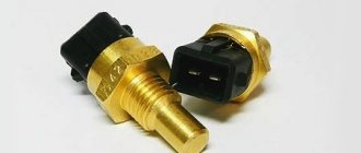
Sensor device
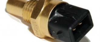
At the dawn of the automotive industry, simple thermal relays were used as coolant temperature sensors (hereinafter referred to as coolant temperature sensors) - they were installed on most internal combustion engines. These sensors can now be found on K-Jetronic single-injection systems and the like. These were used on old Mercedes from the 80s and 90s. How it works? When the relay contact is in the open position, the engine warms up. When the contact is closed, the electronic control unit understands that the engine has heated up to operating temperatures. The concentration and composition of the mixture changes.
Nowadays, thermistors are used as DTOZ. These are resistors that change resistance depending on the temperature of the environment. In the VAZ-2110 car, the coolant temperature sensor is of this type. Heating is monitored continuously, without interruption. Thermistors for these sensors are made from nickel oxide or cobalt oxide. These alloys have a peculiarity: as the temperature rises, the number of free electrons in them increases, due to which the resistance decreases.
The thermistor located inside the DTOZH has a negative temperature coefficient. The maximum resistance level is achieved when the engine is cold. A voltage of +5 V comes to the temperature sensor and as the engine heats up, it decreases. The ECU records the slightest changes in voltage, and thus the coolant temperature is determined.
Sensors with positive temperature coefficients can be installed on engines from Renault and some other power units. They are arranged similarly. However, as the antifreeze temperature increases, the resistance on the sensor does not fall, but increases.
Causes of failure related to injector sensors.
Crankshaft sensor (crankshaft sensor).
If this sensor completely fails, the car most likely will not even start. Crankshaft sensor failure is a fairly rare malfunction, but it does occur. The sensor may give incorrect readings if it is not tightly screwed to the motor housing. Vibration can cause it to change its position in the seat, which is extremely unacceptable. As the distance between the sensor and the drive disk (notches on which the sensor is triggered) increases, engine malfunctions begin. An indirect sign of the need to check the crankshaft sensor is the absence of ignition. It is the pulses from the crankshaft sensor that the ECU uses to calculate the timing of the spark and fuel injection. This means that there may be no spark not only due to a malfunction of the ignition system, but also due to a failure of the crankshaft sensor.
Crankshaft sensor
Camshaft position sensor.
The second reason for the malfunction of the injection motor. If it malfunctions or if an injector breaks down, the engine switches to an asynchronous mixture supply mode. This means that the mixture is injected into the cylinders regardless of the position and stroke of the piston. In such cases, fuel consumption usually increases and the Check Engine light comes on.
Camshaft position sensor
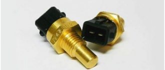
Coolant temperature sensor DTOZH.
The Check Engine light will come on in this case either if the sensor wire is broken or if there is a short circuit. this sensor. If the sensor lies too much and shows the wrong temperature, then the car may not start at all, and the reason is simple.
Imagine that the true engine temperature is +20°C, and the sensor shows -20°C. What happens in this case? The ECU gives a command to inject more fuel, thinking that the engine is cold. As a result, the cylinders are overfilled with fuel and the engine simply choke on gasoline. Even if the car starts, with a faulty temperature sensor there will be increased fuel consumption.
Coolant temperature sensor DTOZH
Please note that a vehicle may have two or more coolant temperature sensors installed. One of them gives readings to the ECU, the second – to the dashboard (in some cars the panel takes readings from the ECU). Carefully study which sensor is in your car, where it is located and what each of them is responsible for.
Oxygen sensor (lambda probe).
If the oxygen sensor breaks down, there will be increased fuel consumption and interruptions in engine operation may occur. The sensor most often continues to work, but its readings differ from the real ones. As a result, the consumption and overall dynamics of the car deteriorate. Interruptions in engine operation may occur. In most cases, an error code is entered into the ECU memory, and a lamp lights up indicating an injector malfunction - Check Engine.
Oxygen sensor (lambda probe)
Mass air flow sensor - mass air flow sensor.
Does the car run intermittently, does the engine start poorly, does it stall while driving or when you release the gas pedal? All these reasons can cause a malfunction of the air flow sensor. If the engine does not start as usual, but only starts when the gas pedal is pressed, then the reason may be the mass air flow sensor. This sensor shows how much air is entering the engine. The ECU, in turn, based on the readings, calculates how much fuel needs to be supplied to the cylinders.
Mass air flow sensor - mass air flow sensor
If the sensor is working properly, then you should check the air leakage after it. Since in this case the real amount of air will differ from the measured one. In general, air leaks are one of the most common problems for an injector. THIS article describes in detail how to easily find and fix air leaks yourself.
Throttle position sensor - TPS.
If the car is “not responsive” to the gas pedal, the speed floats or changes spontaneously, or the idle is unstable, then the cause of the malfunction may be the TPS. The car may not even start if the TPS gives incorrect readings.
Throttle position sensor - TPS
Imagine that you start the engine without pressing the gas pedal, as expected, and the sensor shows the ECU that the pedal is pressed halfway. Of course, the ECU increases the amount of fuel injected, believing that you have pressed the pedal and need to step on the gas. As a result, the cylinders are flooded, the car stalls, or does not start at all. In this case, the Check Engine light may not light up, because the sensor is working, it just gives incorrect readings.
Operating principle of DTOZH
The VAZ-2110 temperature sensor works as follows. The thermistor located inside the sensor is an electronic device with a negative indicator of heating modes. The mode of temperature values up to 130 degrees reduces the resistance within 70 Ohms, and the lower limits at -40° increase the resistance to 107 kOhms.
The detector supplies +5 V to the temperature sensor through a constant resistor located inside it. The element determines the heating level of the antifreeze thanks to the potential difference across a thermistor with variable resistance.
What kind of sensor is this and when does the error occur?
The display of this code informs the driver that a malfunction has occurred in the sensor indicating the temperature of the air supplied to the engine. The malfunction occurs when the signal that the meter sends to the computer is excessively high. Structurally, it is a conventional thermistor (thermistor).
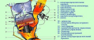
How does the sensor work? When the outside temperature drops, the air becomes rarefied and it is more difficult for it to penetrate into the “inside” of the engine. On the other hand, in hot weather the atmosphere is not so dense and experiences little resistance when sucked into the power unit. The ECU takes into account the data received from the thermistor and sends a command to change the ignition angle, the opening time of the fuel injectors, and also regulates the idle speed. The device is installed in the air pipe, sometimes integrated into the flow meter.
Location of the sensor on the VAZ 2114
Where is it located?
Owners of cars of this model are well aware of various problems associated with this device. Often the device requires replacement. Beginners do not always know where the temperature sensor is located on the VAZ-2110. In cars, this element can be installed in a variety of places.
So, in classic models the thermistor is located directly in the cylinder block. And in AvtoVAZ models of the tenth family you can find DTOZH in the thermostat. By the way, on the VAZ-2110 there is not one temperature sensor - there are two, but the second one does not perform any important tasks. It is connected only to the instrument panel bottom temperature indicator.
When is replacement required?
Checking with your own hands and replacing the temperature sensor on a VAZ 2112 with an injection 16-valve engine is not difficult. Repair of this part is not advisable. If problems arise, you must purchase a new part. A faulty temperature sensor can cause serious problems.
First of all, the engine overheats. If incorrect data is sent to the ECU, the cooling fan will not turn on on time. Consequently:
- antifreeze will boil away;
- the radiator or other components of the cooling system may burst;
- the engine will overheat.
It is worth noting: overheating of the engine makes it impossible to continue normal operation. Major renovation will be required.
Therefore, it is advisable to replace it at the first sign of a malfunction of the temperature sensor. Main symptoms of failure:
- The radiator does not turn on - it starts only at the “command” of the temperature sensor;
- problems when starting the engine - this is especially acute during the first cold weather;
- when the engine is not warmed up - poor exhaust;
- the appearance of steam from the engine - this indicates overheating of the unit;
- Fuel consumption has increased significantly when outside temperatures are above zero.
The price of a temperature sensor is no more than a few hundred rubles. Therefore, it is advisable to purchase a spare one in advance. This will avoid problems associated with finding the part. If you suspect that the sensor is not working, you should replace it immediately. The part is not repairable.C
Sensor malfunctions
As you know, the ratio of fuel and air in the combustible mixture depends on the readings of the device. All owners have already encountered or will continue to encounter various problems that the temperature sensor creates. It also determines whether the fan will start when overheated or not.
You can suspect a malfunction of the coolant sensor on a VAZ-2110 based on the following symptoms. So, the first signs are problems starting the engine on a cold frosty morning. You may also experience poor exhaust and fuel consumption will be significantly increased.
These symptoms do not necessarily indicate that the sensor needs to be replaced. Sometimes it is enough to clean the contacts and clean the sensor itself from corrosion. If a visual inspection fails to identify problems, then you need to check the element.
Troubleshooting
Standard situation: the fan operates in all provided modes, but the heater only blows cold or hot air. In this case, you can conduct a fairly simple test. Turn on the ignition, turn off the heating fan and move the interior temperature control knob to the extreme left (minimum) or extreme right (maximum) position. In this case, you can determine by ear whether the micro-gearbox is working.
If it works, the heater fan is turned on at its fastest speed, and the temperature control is again moved to the far left and far right positions, allowing it to run in each of them for a few seconds. In this case, the sound of the air flow should change; if this is not the case, then this indicates a mechanical break in the connection between the electric motor and the damper or its jamming in one position. This will require further disassembly of the system and restoration of the functionality of the damper.
In a situation where during testing you cannot hear the operation of the micromotor-gearbox, you need to carry out other checks that will help you figure out why the stove temperature regulator is not working. Its handle must be set to the middle position. After this, remove it from its seat on the panel. Without disconnecting the pads, the controller should be turned towards you as much as possible.
We test the supply voltage to the control unit. To do this, you need to take a 12 V test lamp, connect one clamp contact in a small screwdriver, which is inserted into contact 3, with a black wire coming out of it. Insert the second contact into pin 6, which is located under pin 3 and the blue wire comes out of it. If the control lights up when the ignition is turned on, it means that power is supplied to the control unit, and the VAZ 2110 heater regulator stopped working for this reason. For diagnostics to proceed normally, the battery and on-board voltage must be at least 12.5 V.
If power is supplied to the controller, you need to turn off the ignition and disconnect the large X1 block with 13 connectors. Next, you need to take two conductors with contacts that can be connected to the controller plugs. One wire attaches to pin #2 in this connector, it will be the first one on the right in the top row when looking directly at the connector. The second end of the conductor is connected to the positive connector of the multimeter. The other wire connects to connector No. 8, which is located in the top row in 4th place, if you count from the right. The conductor is connected to the negative terminal of the multimeter.
To carry out further measurements, the multimeter is set to voltmeter mode at direct current, with measurement limits up to 20 V. We turn the controller towards ourselves and set the temperature regulator to the middle position. After this you need to turn on the ignition. Small readings in the range of hundredths of a volt may appear on the multimeter; these can be ignored.
The temperature control is turned to the extreme right position (maximum heat). A voltage in the range of 10-11 V should appear on the multimeter screen, which is applied for 10-14 s, after which it disappears.
After this, the regulator is moved to the extreme left position (minimum heat). The same readings should appear on the device in the range of 10-11 V, in the same time period, but with a minus sign. It indicates that the polarity of the connection at the output of the controller has been reversed.
When checking controller 13333854, where the temperature of the VAZ-2110-12 stove is adjusted automatically, you need to know that its polarity at the outputs will be the opposite. That is, in the extreme right position, the multimeter readings will have a minus sign, and in the extreme left position without a sign in front of the readings. Otherwise, its testing is similar.
Thus, repairing the VAZ-2110 stove regulator does not require special skills and tools, and the only complex equipment you will need is a multimeter, which many car enthusiasts have. You can check and troubleshoot problems yourself, including in cases where the damper jams, which will be signaled by one of the control system tests. If a sensor or micro-reducer fails, you can easily change them yourself, since access to them is quite simple. The only serious problem is the failure of the control unit itself, which is practically beyond repair, since it is based on an integrated circuit, so it is easier to replace.
Sensor diagnostics
All car owners should know how to check the temperature sensor on a VAZ-2110. By checking, you can save on the cost of a new device, although its price is not entirely high.
You can test the element by heating it. You need a suitable container. It could be a glass or a teapot. Hot water is poured into it. The water should be heated to approximately 100 degrees - the heating should be monitored with a thermometer. Next, the working part of the device is lowered into water. However, it is precisely the part of the temperature sensor that is located in the motor that needs to be lowered. Contacts must not be in water. Then a multimeter is connected to the contacts and the resistance is measured.
A working sensor at a liquid temperature of 100 degrees has a resistance of 177 ohms. At +50 degrees the resistance is 973 Ohms. If the values do not correspond to the norm, then the faulty element should be replaced. If the indicators are within these norms, then everything is in perfect order.
Understanding the oxygen sensor
It is necessary to determine the sensor articles not by the engine model or even by Euro standards, but only by the ECU unit.
Types of oxygen concentration sensors (OCC)
The number of oxygen sensors can be two or one - it all depends on environmental standards. AvtoVAZ also used two types of sensors - 0 258 005 133, 0 258 006 537 (BOSCH part numbers). The first of them are compatible with BOSCH M1.5.4, MP7.0 and January 5.1 controllers. Newer sensors were connected to the BOSCH M7.9.7 ECU (January 7.2). The two different types of sensors differ even in appearance.
The red arrow marks the first, that is, the main sensor. The top photo corresponds to engine 21124 (1.6 l).
Sensor locations (21124 and 21120)
VAZ-21120 engines (1.5 l) could meet the Euro-3 standard, and then an “extended” catalyst was welded behind the main sensor. The second sensor was located behind it, that is, behind the “can”. Let's clarify:
- The Euro-2 standard corresponds to a design with one sensor (main);
- During the transition to Euro-3 standards, a second sensor was added (blue arrow).
By the way, the 24th engine can meet Euro-4 standards.
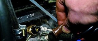
How to remove
First of all, they look at what is preventing you from getting to the thermostat and sensor. The air filter housing is in the way - it needs to be removed. Next, it is recommended to drain the antifreeze from the engine, but this is not always necessary. When replacing, only a little fluid will spill, and you can always top it up to the level.
Then, after draining the liquid, remove the terminal from the battery, select the desired sensor and remove everything connected to it. After disconnecting, the element is simply unscrewed, holding its edges with your hands or a key. After this, the device can be removed.
Diagnosis of VAZ 2112 16 valves with your own hands. Why pay extra?
In addition, despite modern equipment, the level of diagnostics in services is practically not growing. Not everywhere there are specialists who can correctly assess the condition of the car. Therefore, in most cases, self-diagnosis will be the best option.
True, special devices may be needed to carry it out, but their purchase will more than pay off in savings on trips to a car service center. It should be noted that the tenth VAZ family has the same microcontroller installed. Therefore, instrument diagnostics are performed here in the same way.
Visually. Do-it-yourself diagnostics of a VAZ 2112 16 valves begins with an inspection of the car. Carefully inspect all components
Pay special attention to the suspension and steering. Parts must not have cracks or other damage
The brakes and body are also inspected. All these design elements are important for the normal operation of the car. However, many of their faults can be seen with the naked eye.
The twelfth model uses the January-4
" This device constantly diagnoses the condition of the vehicle. All detected faults are stored in the controller’s memory and remain there until they are erased. The source of the problem can be determined by the two-digit code. Codes from 12 to 61 inclusive are used here.
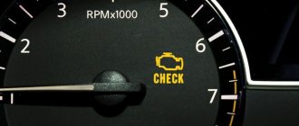
For timely detection of errors and diagnostics, there is a “CHECK ENGINE” light on the dashboard; in common parlance it is referred to as a “check”. This lamp is connected to a microcontroller. And when a malfunction occurs, it lights up. Signaling the need for an urgent check of all engine systems.
When the ignition is turned on, the light comes on and all engine systems are checked. If there are no breakdowns, the “check” goes out when the engine is started. If the malfunction is intermittent, then “CHECK ENGINE” will light up and go out. Please note that intermittent problem codes are also stored in memory and may interfere with diagnostics or, conversely, provide clues about the true cause of the failure.
To read error codes, you will have to use the connector located at the bottom left of the dashboard. Diagnostics can be carried out in two ways:
- Diagnostic scanner (let’s just say EML 327 is not suitable);
- Counting the "check" flashes.
To check for errors using a lamp, connect output “B” of the diagnostic block to the “minus” of the machine. The easiest way to do this is to connect this output to output “A”, which is “ground”. After this, the key is turned to the “ignition” position. You need to carefully monitor the behavior of “CHECK ENGINE”. To begin with, the light will display the diagnostic system operating code. It will look like a flash, pause, flash, flash. This means - 12. This code is repeated three times. After it, the system issues fault codes.
It's easy to decipher them
. The first part of the flashes means dozens, then there is a pause and another one to nine flashes occur. This is what makes up the fault code. If there is no code “12” the problem is in the controller itself. All codes will be displayed 3 times.
You cannot disconnect contacts immediately after completing the diagnostics. This may damage the diagnostic device. First the ignition is turned off. Only after 10 seconds should the contacts be opened.
It is much easier to diagnose using a scanner. If it is not available, you can use a laptop. Just download the test program and get a USB adapter (K-Line adapter). The majority of programs evaluate a large number of parameters in addition to errors. You can view and evaluate all the main indicators of the motor. This option will be the most optimal.
Reset errors
. The controller remembers errors and will show them even after the fault has been eliminated. Therefore they need to be reset. This is the only way to ensure that the problem is corrected correctly. To reset, turn off the power to the device for 15 seconds. To do this, simply remove the negative terminal from the battery. Do not perform this action with the ignition on. This may damage the controller.
Conclusion
. Any car owner wants to control its condition. Constantly going to the service center to check is quite expensive. Therefore, diagnosing the VAZ 2112 16 valves yourself is the most optimal solution. The great thing is that you can do it at any convenient time.
- Diagnosis of HBO 4th generation with your own hands. When it makes no sense to pay a service station
- Do-it-yourself diagnostics of the Gazelle 405 engine. Not interesting for long
- DIY diagnostics of VAZ 2114 and 2115. Find out everything that's broken
- DIY Ford Focus 2 diagnostics. Learning to avoid service stations
Installing a new coolant sensor
The new coolant temperature sensor on the VAZ-2110 is installed in the reverse order. Experienced motorists recommend lubricating the threads of the element with sealant.
Sometimes coolant leaks are observed from under the new sensor. The replacement process is extremely simple and even beginners who just got behind the wheel and didn’t know anything about cars can handle it without difficulty.
Causes of failure of the coolant temperature sensor
Structurally, the coolant sensor is quite simple, and accordingly, it rarely fails. Usually this happens simply due to its old age or mechanical damage. For example, corrosion of contacts and metal parts of the case may occur due to the fact that instead of antifreeze or antifreeze, ordinary water was poured into the cooling system (and even more so if this water is “hard”, that is, with a high content of metal salts). Also, the reasons for the failure of this device may be:
- Damage to the body. This can be expressed in various aspects. Often, leaks of coolant are visible, which flows from the threads of the sensor or its housing. Also, the electrical contacts and/or the thermistor itself may be damaged, which will produce an incorrect signal.
- Oxidation of contacts. Sometimes situations arise when, under the influence of fumes or simply from old age, the contacts on the sensor oxidize, so the electrical signal does not pass through them.
- Damage to the chip. In some cases, due to mechanical damage, the so-called “chip” may fail, that is, a group of contacts that is connected to the coolant temperature sensor. Simply put, the wires at the base of the connector fray. According to statistics from reviews found on the Internet, this is one of the most common malfunctions that occurs with the sensor and the corresponding system.
- Lost electrical contact inside the sensor. In this case, unfortunately, repair is hardly possible, since usually its body is sealed and does not allow access to the insides of the DTOZH. Accordingly, in this case the sensor only needs to be replaced with a new one.
- Violation of wire insulation. In particular, we are talking about the power and signal wires that go to the sensor from the electronic control unit and back. The insulation can be damaged due to mechanical stress, abrasion, or even simply from old age, when it “peeles” in pieces. This is especially true for those machines that are operated in conditions of high humidity and sudden changes in ambient temperature.
If it is possible to simply clean the body/threads/contacts of the sensor, then to restore its normal operation it is enough to carry out the appropriate measures. However, if the housing is damaged and/or the internal thermistor is damaged, then repair is hardly possible. In this case, you just need to replace the sensor with a new one. Its price is low, and the replacement process is simple and will not take much time and effort even for novice car owners.
Reasons for error P0113
In diagnostic devices, this “trouble” is called Intake Air Temperature Sensor High. The described error p0113 appears in only four cases, which is due to the simplicity of the sensor design:
- malfunction of the thermistor itself;
- a violation in the sensor’s power supply circuit—one of the wires is shorted or broken;
- there is no electrical contact in the connecting block;
- a layer of dirt and (or) oil stains settling on the sensor, reducing the sensitivity of the thermistor.
The “error 113” indication can appear on any modern car, both Russian and foreign made. It could be Mercedes with Audi or VAZ 2112, 2114, GAZ, UAZ.
An intake air temperature sensor is installed on any modern engine. Sometimes the reason is quite banal. Error 0113 on a VAZ 2114 or VAZ 2115, 2110, 2111, 2107-2109 (injector) sometimes appears after the car has been parked for a long time without use, when the battery is too, but not completely, discharged. Charging it restores the functionality of the machine's systems, including the air temperature sensor.
We check the mass air flow sensor on a VAZ-2110 with a multimeter
The sensor block, the first wire may not be there - this is normal.
To do this, we need to understand the pinout and the sensor connection diagram. As you can see, the block has only five wires:
- + 12 Volt.
- + 5 Volts.
- Total ground (green wire).
- Air temperature output signal.
- Air flow signal output (yellow wire).
Electrical diagram for connecting the mass air flow sensor.
The pinout may differ in different firmware versions and on different sensors. Everything is clear with the first two contacts - take a multimeter and check the presence of voltage when the ignition is on. If there is no signal, we look for the cause either in broken wires or in poor contact. Now we check the main indicator - the accuracy and magnitude of the air flow signal. By the way, this can be checked without a multimeter, using the on-board computer, if one is installed:
- We go to the menu, look for sensor parameters.
- Find the voltage Udmrv.
- The rating for all of the above modifications is from 0.996 to 1.01 V.