The fuel system (power system) of VAZ 2108, 2109, 21099 cars consists of a fuel tank, fuel lines, a fuel pump, a carburetor, cold and hot air intakes and an engine air filter. It serves to supply fuel to the car engine and prepare the fuel mixture (fuel/air) necessary for different engine operating modes.
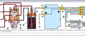
Diagram of the fuel system of VAZ 2108, 2109, 21099 cars
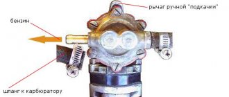
Fuel is pumped by a mechanical fuel pump from the fuel tank through an intake with a strainer into the main fuel line. Next, it enters the carburetor, where it is mixed with air coming from the engine air filter. The carburetor prepares the fuel mixture (air/fuel) in a certain proportion necessary for the engine to operate in one mode or another.
Notes and additions
— The fuel tank of VAZ 2108, 2109, 21099 cars has a capacity of 43 liters. The gasoline used in these vehicles is AI-91, AI-95.
More articles on the fuel system
Carburetor engine power system
1 — fine fuel filter; 2 – fuel supply hose to the fuel pump; 3 – fuel pump; 4 – heated air intake; 5 – check valve; 6 – fuel drain hose from the carburetor; 7 – cold air intake; 8 – thermostat; 9 – air filter assembly; 10 – carburetor; 11 – fuel drain pipe; 12 – fuel supply pipe from the tank; 13 – fuel tank; 14 – flange of the fuel level sensor and fuel intake tube; 15 – separator hose; 16 – filling pipe hose; 17 – filling pipe; 18 – fuel tank plug; 19 – separator; 20 – two-way valve hose; 21 – two-way valve
Possible malfunctions of the RTD
Considering that the design of the pressure regulator is mechanical, malfunctions in its operation can occur quite often. The most common device malfunctions include:
- weakening of the membrane spring;
- valve jamming;
- regulator clogging;
- violation of the tightness of the junction of the regulator and the ramp body.
When the diaphragm spring weakens, the valve cannot cope with the air pressure coming from the intake manifold. As a result, the pressure and amount of incoming fuel are reduced.
Valve jamming leads to an uncontrolled supply of fuel to the manifold and its “waste” into the fuel line. In this case, gasoline consumption increases, and the engine stops starting normally due to interruptions in the fuel supply.
Similar signs of malfunction can be observed when the regulator is clogged. Dirt and deposits reduce the throughput of the system, as a result of which the fuel pressure decreases significantly, the engine “chokes”, and normal idle speed disappears.
If the seal between the regulator and the ramp is broken, the air pressure may drop, which again will lead to a decrease in fuel pressure.
Adjusting the ignition angle
Sluggish acceleration of the car and instability of the idle speed are also often associated with incorrectly set ignition; this procedure is mainly carried out in car repair shops using special equipment. But if you wish, it’s easy to make the adjustment yourself, and without a strobe, and quite accurately:
- with the engine stopped, loosen the three nuts securing the distributor (the third fastening is located at the bottom, it is not visible from above);
- we start the car, turn the distributor-distributor clockwise (to “+”), and if the ignition was late, the idle speed will increase noticeably;
- we select the optimal position of the distributor (the operation of the internal combustion engine should be smooth, without failures), reduce the speed using the quantity screw, turn off the engine, fix the distributor-distributor with one nut for now, and check the results of the ignition adjustment on the fly.
If, under heavy load and sharp acceleration, your fingers begin to noticeably “knock” (engine detonation appears), you should move the distributor a little to “minus”, then check the car again while driving. This way you can set the ignition quite accurately, and sometimes even better than with a strobe light.
Rail pressure without return
How the fuel system works
Increasing the engine power of a car with a 2108 Solex carburetor.
Fuel is supplied to the ramp under excess pressure (6 atmospheres), which is created by the fuel pump. Using the pressure regulator on the nozzle, a constant pressure drop of 3 atmospheres is maintained. At constant pressure and a linear characteristic of the injectors, the amount of fuel injected is determined by the duration of the injector control pulse.
How to check?
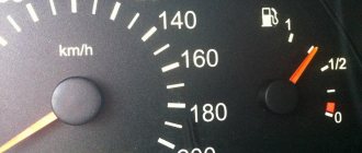
Let's connect the pressure gauge to the fuel rail. With the fuel pump turned on and the engine not running, the pressure should be 2.8-3.2 atmospheres. If the engine is idling, the pressure should drop to 2.2-2.5 atmospheres. When over-gassing, the pressure gauge needle should deviate into the zone of 2.8-3.2 atmospheres.
Now let's check the operation of the injectors. With the engine not running, we will create the required pressure in the ramp (2.8-3.2 atmospheres), after which, using diagnostic equipment, we will apply a series of test pulses to the first injector, monitoring the change in pressure. The above procedure must be carried out for all injectors. The pressure drop should be the same in all cases. If the results of checking the fuel pressure correspond to those described above, the fuel supply system is working properly.
What will happen if the fuel pressure in the rail is low (less than 2 atm.) or high (more than 4 atm.)? The amount of fuel injected will change in proportion to the pressure deviation from the norm. In other words, the air-fuel mixture will become lean or rich.
It will be especially painful in engine control systems without oxygen sensor feedback, since the controller does not know about the malfunction and continues to calculate the fuel supply for a normal fuel pressure value. In control systems with an oxygen sensor, the controller can compensate for changes in the composition of the air-fuel mixture, but only within reasonable limits.
Troubleshooting
Let us recall the composition of the fuel supply system. It includes: a fuel tank with an installed submersible fuel pump, a fuel filter, fuel lines (supply and drain lines), an injector ramp and a pressure regulator. Any component failure can cause incorrect fuel pressure. Let's try to list common faults for each component.
Gas tank. Through special pipelines, the gas tank communicates with the atmosphere, which prevents its deformation (flattening). If the connection with the atmosphere is broken, a vacuum is created inside the gas tank. In this case, the pressure in the fuel rail may be low.
Gasoline pump. There are several malfunctions:
- the fuel pump does not develop the required pressure, resulting in low fuel pressure;
- the check valve of the fuel pump does not hold pressure, as a result - a rapid drop in pressure after turning off the ignition;
- contamination of the fuel pump mesh filter, as a result - reduced pump performance, which affects the dynamic operating conditions of the engine.
What is a fuel pump? Principle of operation
Fuel lines may be pinched. If this happens to the supply line, then the fuel pressure will be reduced, if it happens to the drain line, it will be increased. In addition, the use of low-quality gasoline with a high tar content can lead to a decrease in the capacity of fuel lines.
Fuel pressure control. There are regulators with a stuck diaphragm in the open or closed position. In the first case, the fuel pressure in the system will be reduced, in the second - increased.
It stalls at idle without any choke. After hitting the wheel.
Good afternoon, a week ago a friend and I were driving along an intersection and hit the right wheel twice. The problem is that before the car started and ran cleanly and smoothly, the exhaust came out of the pipe evenly. But after the impact, we drove another 100 meters, stopped (by myself) and tried to get going again... and at first the engine simply stalled in gear, and almost immediately the engine began to pick up speed and drop it on its own, the tachometer needle twitched and you could hear the engine itself picking up speed and resets AS IF someone is pressing on the gas. Somehow we set off with the choke pulled out and arrived at the parking lot. And for a week now I can’t figure out what the problem is. I thought it was the idle speed sensor. I checked it by pulling it out and turning it on while the engine was running, the result was 0 as it did not work smoothly and still works. And only with the choke pulled out (temperature between 50 | 130), if you press the choke in, it immediately loses speed and stalls. I removed the carburetor. Cleaning and washing. I'll post after installation. But I would still like to hear what else could be the problem?
Checking the valve with a multimeter
Malfunctions of the distributor of VAZ 2108, 2109, 21099 cars
Diagnostics can also be done with a voltmeter. How to check the fuel canister check valve? You need to open the hood and disconnect the wiring harness connector from the valve. Next, connect the negative probe of the multimeter to ground and turn on the ignition. Then bring the positive probe to the wire chip and look at the values of the device. The readings should not be lower than 12 V.
To inspect the valve itself, loosen the hose clamp with a screwdriver and remove the tube outward. Next you need to remove the valve itself by prying it off with a slotted screwdriver. It is necessary to turn on the ignition and apply “plus” and “minus” to the corresponding terminals on the element. If the valve is working properly, you will hear a characteristic click. Otherwise, the element is defective and must be replaced. The cost of a new element is 350 - 370 rubles (suitable for a VAZ of the tenth family).
To replace the valve, you only need to unscrew the clamps of the gasoline hoses and pry off the edges of the element. The new one must be installed tightly into the grooves until it clicks. Next, put the hoses on the valve and tighten the clamps. At this point, the replacement of the Semyorka adsorber valve has been successfully completed.
Where is the check valve located?
You need to know the enemy by sight, so let's start by looking for a check valve in car power systems. The valve can be installed in the fuel pump housing of injection engines, on the fuel rail, or simply in the fuel line between the gas tank and the fuel injectors. On diesel engines, it is installed between the low-pressure hand pump and the injection pump so that the pressure at the inlet to the high-pressure pump is always stable. This system is installed on all KAMAZ 740, Tatra, MAN and Renault Magnum engines. In diesel engines with a fuel preheating system, a check valve is necessarily installed in front of the heating system, as in Magirus trucks, the same KAMAZ of the Arctic version, and many others.
The check valve for injection engines may be located on the fuel frame
In domestically produced passenger cars with injectors, the 16-valve VAZ 2110, 2114, the check valve is installed in the fuel pump and on the fuel rail, similar to the diesel system. In old carburetor cars, VAZ 2108, 2109, classic rear-wheel drive models, the role of a check valve is played by the fuel pump itself, which is installed on the cylinder block and does not allow fuel to flow back into the tank, thanks to the sealed outlet valve of the fuel pump. When the valve loses its tightness, the gasoline goes completely into the tank, and the engine can only be started with manual pumping.
Prudent owners independently installed return valves to make starting the engine easier. On old models of the Opel Cadet, Mazda 323, when starting was difficult, it was enough to buy and install a check valve into the power system closer to the carburetor or mono-injector, and the fuel stopped flowing through the working line into the tank, and the start became normal even at sub-zero temperatures.
Article: 2108-1156010
Order code: 001030
- Buy with this product
- show more
Passenger cars / VAZ / VAZ-21071 drawing
» href=»/catalog/vaz-3/legkovye_avtomobili-30/vaz_2107-8/truboprovody_toplivnye-84/#part23675″>Fuel valvePower system / Fuel pipelines
- Passenger cars / VAZ / VAZ-21092 drawings
- » href=»/catalog/vaz-3/legkovye_avtomobili-30/vaz_2109-9/truboprovody_toplivnye-90/#part32361″>Fuel valvePower system / Fuel pipelines
- » href=»/catalog/vaz-3/legkovye_avtomobili-30/vaz_2109-9/truboprovody_toplivnye-89/#part32327″>Fuel valvePower system / Fuel pipelines
- Passenger cars / VAZ / VAZ-21101 drawing
- » href=»/catalog/vaz-3/legkovye_avtomobili-30/vaz_2110-10/truboprovody_toplivnye-116/#part40666″>Fuel valvePower system / Fuel pipelines
- Passenger cars / VAZ / VAZ-21121 drawing
- » href=»/catalog/vaz-3/legkovye_avtomobili-30/vaz_2112-12/truboprovody_toplivnye-116/#part49282″>Fuel valvePower system / Fuel pipelines
- Passenger cars / VAZ / VAZ-21314 drawing
- » href=»/catalog/vaz-3/legkovye_avtomobili-30/vaz_2131-73/truboprovody_toplivnye-101/#part62846″>Fuel valvePower system / Fuel pipelines
- » href=»/catalog/vaz-3/legkovye_avtomobili-30/vaz_2131-73/truboprovody_toplivnye-101/#part62847″>Check valve Power system / Fuel pipelines
- » href=»/catalog/vaz-3/legkovye_avtomobili-30/vaz_2131-73/truboprovody_toplivnye-99/#part62799″>Fuel valvePower system / Fuel pipelines
- » href=»/catalog/vaz-3/legkovye_avtomobili-30/vaz_2131-73/truboprovody_toplivnye-99/#part62800″>Check valve Power system / Fuel pipelines
- Passenger cars / VAZ / VAZ-21142 drawings
- » href=»/catalog/vaz-3/legkovye_avtomobili-30/vaz_2114-647/truboprovody_toplivnye-18/#part1669166″>Fuel valvePower system / Fuel pipelines
- » href=»/catalog/vaz-3/legkovye_avtomobili-30/vaz_2114-647/truboprovody_toplivnye-18/#part1669167″>Check valve Power system / Fuel pipelines
- Passenger cars / VAZ / VAZ-212131 drawing
- » href=»/catalog/vaz-3/legkovye_avtomobili-30/vaz_21213-731/truboprovody_toplivnye-66/#part2009240″>Fuel valvePower system / Fuel pipelines
- Passenger cars / VAZ / VAZ-21084 drawings
- » href=»/catalog/vaz-3/legkovye_avtomobili-30/vaz_2108-18/truboprovody_toplivnye-81/#part28046″>Fuel valvePower system / Fuel pipelines
- » href=»/catalog/vaz-3/legkovye_avtomobili-30/vaz_2108-18/truboprovody_toplivnye-80/#part28016″>Check valve Power system / Fuel pipelines
- » href=»/catalog/vaz-3/legkovye_avtomobili-30/vaz_2108-18/truboprovody_toplivnye-80/#part28015″>Fuel valvePower system / Fuel pipelines
- » href=»/catalog/vaz-3/legkovye_avtomobili-30/vaz_2108-18/truboprovody_toplivnye-81/#part28047″>Check valve Power system / Fuel pipelines
- Passenger cars / VAZ / VAZ-210992 drawings
- » href=»/catalog/vaz-3/legkovye_avtomobili-30/vaz_21099-79/truboprovody_toplivnye-90/#part36300″>Fuel valvePower system / Fuel pipelines
- » href=»/catalog/vaz-3/legkovye_avtomobili-30/vaz_21099-79/truboprovody_toplivnye-89/#part36266″>Fuel valvePower system / Fuel pipelines
- Passenger cars / VAZ / VAZ-21111 drawing
- » href=»/catalog/vaz-3/legkovye_avtomobili-30/vaz_2111-11/truboprovody_toplivnye-116/#part44974″>Fuel valvePower system / Fuel pipelines
- Passenger cars / VAZ / VAZ-21152 drawings
- » href=»/catalog/vaz-3/legkovye_avtomobili-30/vaz_2115-65/truboprovody_toplivnye-80/#part53090″>Fuel valvePower system / Fuel pipelines
- » href=»/catalog/vaz-3/legkovye_avtomobili-30/vaz_2115-65/truboprovody_toplivnye-80/#part53091″>Check valve Power system / Fuel pipelines
- Passenger cars / VAZ / VAZ-2110, 2111, 21121 drawing
Causes of fuel pressure regulator malfunctions
RDT may fail for several reasons. For example, defective parts are found on Russian-made cars. There are significantly fewer defects on foreign models, but you can purchase a defective RTD by purchasing a non-original spare part.
Mostly the check valve breaks down due to natural aging. Let's say this can happen after a hundred thousand mileage or more. It should be noted that check valve failures are not common. Most often, in an RTD, the membrane dries out over time, less often the valve jams, and even less often the spring breaks or weakens.
Sensor failure may occur due to low-quality gasoline. For example, in winter, fuel was filled with water, and water got into the regulator. If the fuel filter is not replaced on time, dirt gets into the parts of the power system, including the regulator. In this case, the RTD valve most often jams. It’s hard to imagine what could happen to the spring, but apparently, it still breaks sometimes.
Device and principle of operation
The check valve device is simple. The entire mechanism consists of a spring, a membrane and the valve itself. The ball-type valve is equipped with a special seat, which is made of soft metal and is calibrated as accurately as possible.
The valve body is equipped with three outlets: the first is for the intake manifold, and the others are for fuel removal. Fuel moves freely through the valve in only one direction.
It is not able to flow back into the valve due to the pressure created on it, which is why it closes. The valve opens due to the movement of the spring resulting from the vacuum as the engine speed increases. Excess fuel is returned back to the fuel tank.
The check valve for diesel fuel is no different in operating principle from its “brother” used in gasoline engines; differences can only arise in the location of this unit.
As mentioned above, wear and tear is often caused by time and poor quality fuel. If gasoline or diesel fuel is mixed with water, then such a mixture will be destructive for many units of the fuel system.
Valve clogging as a result of using low-quality fuel can also be a significant cause. Clogging generally leads to a decrease or cessation of the performance of many vehicle components (for example, air filters).
Once fuel is mixed with water and enters the system, moisture may enter the regulator. Often along with dirt if the filter is faulty.
We also recommend reading our expert’s article, which talks about where the fuel filter is located.
You may also be interested in our author's article on how to remove a faulty fuel pressure regulator.
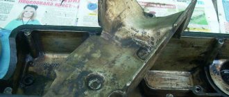
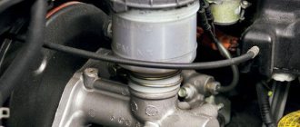
“Return” of the fuel system of an engine with a Solex carburetor, VAZ 2108, 2109, 21099 cars
The power supply system (fuel system) of an engine with a Solex carburetor, front-wheel drive VAZ 2108, 2109, 21099, has two lines: a fuel supply from the gas tank to the carburetor and a return line from the carburetor to the gas tank (“return”). The return line is designed to drain excess fuel from the carburetor when the car engine is running in different modes.
Solex carburetor fuel return system design
— Fuel return fitting with calibrated hole
Designed to limit the volume of fuel drained into the return line. This ensures optimal pressure in the fuel line from the fuel pump to the carburetor needle valve.
— Fuel return line
Rubber hoses and a metal tube under the bottom of the car from the fuel return fitting of the carburetor to the fitting on the fuel pick-up in the fuel tank, through which excess fuel is drained into the fuel tank.
— Check valve
Only allows fuel to flow in one direction. Designed to prevent fuel from spilling out of the gas tank when the vehicle rolls over.
Operating principle of the Solex carburetor fuel return system
When the engine is running, the fuel pump creates a certain pressure in the fuel supply line up to the needle valve. This pressure is excessive for normal operation of the carburetor needle valve (possible “overflow”). Therefore, excess fuel is discharged through a fuel outlet fitting with a calibrated hole into the return line and then into the gas tank. This ensures normal operation of the carburetor and car engine, cooling of the fuel pump and the fuel passing through it due to its constant circulation, and removal of air pockets from the fuel pump and fuel supply line. A calibrated hole in the fuel return fitting, which meteres the volume of drained fuel, ensures that the required pressure is maintained in front of the carburetor needle valve.
Fuel return system malfunctions
The main malfunctions are clogging of the return line and failure of the check valve. As a result, the drain line stops functioning normally, the fuel pressure on the needle valve increases, it begins to pass it into the float chamber, the level in it rises, causing excess fuel to enter the engine through the carburetor GDS system. The fuel mixture becomes very rich. As a result, spark plugs flood and interruptions in engine operation in different modes. Among other things, the fuel pump overheats greatly, and air pockets form in it and the supply line. The engine stalls. In some cases, a wet rag placed on top of the fuel pump helps to quickly restore the functionality of the fuel pump.
Therefore, the permeability of the return line and the check valve of the fuel system must be periodically checked (blowed in the direction of the gas tank, with the cap removed from its filler neck); if clogged, it must be cleaned. Notes and additions
— In addition to the above, the fuel return system to the gas tank prevents a sharp increase in fuel pressure on the carburetor needle valve after stopping the car engine.
— An increase in fuel pressure at the carburetor inlet can also occur due to a malfunction of the fuel pump valves or incorrect adjustment of its drive.
More articles on the fuel system of carburetor engines
— Ventilation system for the gas tank of carburetor engines of VAZ 2108, 2109, 21099 cars
— Cleaning the gas tank of VAZ 2108, 2109, 21099 cars
— No fuel supply to the carburetor, causes, elimination
Operation “K” - we repair the carburetor
The VAZ 21099 carburetor is located under the car's air filter cover. If you buy a new carburetor, then you should not try to disassemble or adjust it, since it is already set to the required function from the factory. Every time after you remove or replace the carburetor, it is worth washing it, as dirt can get into the internal channels of the carburetor.
To get the carburetor, you need to use a 10mm wrench to unscrew the air filter cover and slide the four latches that hold it in place. Next, you should loosen the clamps that are attached to the air filter and unscrew the four studs that hold the filter housing and carburetor. After this, you need to loosen the carburetor fuel system clamps and carefully remove them. Next, disconnect the contact wire of the solenoid valve and unscrew the carburetor cover. It must be removed in such a way as not to catch the walls of the float chamber.
Place all unscrewed screws in a separate box - searching for lost fasteners will take a lot of time, and not every store has them freely available. After disassembling the carburetor, you need to check the positions of the floats in the chamber and, if possible, adjust them. The chamber floats should be parallel to the imprint of the chamber walls; this parallelism is clearly visible on the cardboard gasket of the lid. If it is not there, then you need to dilute or reduce the floats to the desired result.
After performing this procedure, the floats should move freely in the chamber and not touch its walls. The distance between the protrusions on the floats and the cardboard spacer should be on average 1 mm; it is best to measure this distance with a caliper.
If there are significant deviations, then the fuel level in the chamber is incorrect. The fuel level should correspond to the red stripes that are in the chamber; it is best to look at them immediately after removal, so that the gasoline does not have time to evaporate. You can also navigate along the ribs in the fuel chamber; to do this, you need to bend or bend the float tongue and pump fuel into the chamber manually. This method is also very good and has proven itself in practice.
Product design differences
There are shut-off elements that move parallel, perpendicular or at an angle to the pipeline axis. The valve is located in a special recess - a seat, into which it is able to lower under its own weight, depending on the temperature of the pipes
That is why, when installing individual models, it is important to observe the position of not only the flow direction arrow, but also the location of the guide elements of the locking part
The main component of the check valve is the internal lock, which can take different shapes:
- a spool consisting of locking plates and a rod;
- solid or halved disk;
- ball with sealing gaskets and a spring mechanism.
Valves with a diameter of more than 400 mm are equipped with a disk that can strongly push against the body when returning to the seat, which leads to damage to the device. To avoid premature wear of the valves, such valves are additionally equipped with hydraulic dampers that ensure smooth movement of the disc. One way or another, such models are rarely found on sale anymore.
Smaller ball or butterfly valves are more popular and in demand. In the first case, the shut-off device is a small ball that moves in different directions depending on the direction of the water, and in the second, two halves of the disk are attached to one rod and, if necessary, ensure that the pipe is closed. It is worth noting that there are also non-return valves that force the valve to open or close. In this case, the flow is controlled by automatic or mechanical devices, but such units are used exclusively in the industrial sector.
Installation of SAUVZ
The system is supplied with a gearmotor, the housing of which contains a built-in electronic board and the necessary wires for connection. Software settings are individual for each car model and are set by the driver. The design of the gearbox uses plastic parts, which eliminates the formation of frost inside. Traction force ensures movement of the damper in any frost.
The device is installed in accordance with the user manual. First we connect the ground. To do this, attach the required cable to the nearest convenient place. After this, we connect the wires to the power plant speed sensor and to the handbrake button-lamp.
We attach the temperature sensor, which is supplied in the kit, to the cooling system hose (SOD), closer to the engine block. It is recommended to cover the sensor to prevent cold air from blowing in. This will eliminate the possibility of underestimating the SOD temperature readings.
After this, we connect the power directly to the battery or through the ignition key. It is not recommended to connect directly to the ignition coil terminal, as there may be large interference. If there is no other way out, then the connection to the ignition coil connector must be made only through an additional relay.
To fasten the gearmotor, a set consisting of a plate, a traction lever, a cable clamp, bolts, washers and nuts is provided. Flexible traction (cable) must be purchased separately. SAUVZ is mounted next to the carburetor. In this case, the damper control cable should be as short as possible and without bends.
Depending on the type of carburetor, you can install the auto choke directly on the carburetor, so that the damper is controlled by turning the air intake axis without a cable. In this case, you will have to do the fastening yourself.
We remove the flexible rod that goes from the passenger compartment to the damper and replace it with a new cable. It must be connected to the gearbox. The auto-suction pump is attached to the plate using bolts and nuts with washers. To adjust the installation height of the drive, additional nuts are provided. The plate with the lever is mounted between the main plate and the gearmotor. We thread the central core of the flexible rod into the hole of the lever and form it. We fix the shell on the plate, adjusting the desired position. The lever assembly must be placed on the drive axis in the “extended” position.
Problems
Why does OK fail? This happens quite often, since the market today has become more defective as a percentage.
Chinese counterfeits at low and medium prices attract the attention of motorists who do not suspect a trick. It is worth installing such a part, and after a while problems arise
How to check the fuel system check valve
If the part is of high quality, then the malfunction occurs for a natural reason - due to wear. As a rule, either the spring or the membrane deteriorates. It is extremely rare for the valve to fail completely, which is a credit to it.
Another common cause of failure that we have seen lately is low quality fuel. Gasoline or diesel fuel mixed with water is harmful to many parts of the fuel system.
Typical symptoms of an OK malfunction look like this:
- the speed changes unexpectedly in idle mode;
- the engine starts only after pressing the gas pedal, although previously it started only by twisting the starter;
- at low speeds the engine operates extremely unstable;
- Liquid leaks from the supply and return fuel pipes, although the sealing of the hoses is beyond doubt.
OK has a mechanical design. On the one hand, it seems to be good and can be easily fixed if you understand the mechanics. In fact, the element is non-separable, and it is impossible to diagnose its functionality using electronic devices, sensors, for example.
Ways to check functionality OK
Various methods are used to determine the serviceability of the valve. One of them is based on checking the pressure level. It is measured by a pressure gauge connected to that part of the system that supplies the engine with gasoline. The normal pressure level should be 3 kg/cm2 (passenger cars). Also, the level should not drop sharply when the engine is stopped. Otherwise, this also indicates a malfunction of the return valve.
Pressure gauge
Some experts advise checking OK by squeezing the return hose. In this case, if everything is in order with the valve, the pressure level should increase. The method is suitable for those machines in which the “return” is made of a rubber hose. However, many cars are equipped with metal pipes or the “return” is too short, it is impossible to compress it.
There is another diagnostic method, without a pressure gauge, suitable for engines that are unstable and have difficulty picking up speed. Again, the return line is pinched. At the same time, you need to monitor the operation of the internal combustion engine. If the engine speed increases and all cylinders are functioning normally, the OK is most likely faulty.
Obviously, nothing good can be expected from a damaged valve. A drop in engine speed, unstable cylinder operation, difficult starting, airing - all this will come sooner or later if the valve does not work.
Clamp the return line
It will be interesting to consider the reason for the airing of the system, which opens our eyes to the principle of operation of the OK. After stopping the engine, a certain amount of fuel liquid must remain in the chamber, awaiting the next start. If there is no valve or it is damaged, gasoline/diesel goes back into the tank, and air takes its place. Until the system is ventilated and the pressure is brought back to normal, the engine will not start.
The best cheap processor car radios
ACV ADX-901BM
pros
- good and clear car sound
- clear controls
- Bluetooth
- optimal price-quality ratio
Minuses
no significant shortcomings were noted by users
From 3,020 ₽ ON GOODS PURCHASES YANDEX.MARKET
ACV ADX-901BM is equipped with a monochrome LED display. The model has good acoustics, has low and high pass filters, and a 13-band equalizer. Supports MP3, WMA, FLAC formats.
KENWOOD KMM-304Y
pros
- many audio settings
- adjustable RGB backlight
- excellent sound quality
- good full crossover
- small price for such functionality
Minuses
squeaks when pressing buttons
From 4100 ₽ ON GOODS PURCHASES YANDEX.MARKET
KMM-304Y is a cheap processor radio from the KENWOOD brand. Equipped with a two-line LCD display with variable backlight. High-quality sound tuning is provided by a 13-band equalizer and tone compensator. The device plays MP3/WMA/AAC/WAV formats, and can read tracks from iPhone/Android.
Let's consider the principle of operation of the gas pump.
Replacing generator bearings on a VAZ 2110 with your own hands, what bearings cost numbers, which ones are better to choose, LuxVAZ
As already mentioned, a mechanical fuel pump is more often used in cars with a carburetor, where the fuel mixture circulates under low pressure. Electric analogues, in turn, are often installed in cars with an injector, where the fuel mixture circulates under high pressure. If the vehicle is equipped with a carburetor, the fuel pump functions as follows. At the moment when it becomes necessary to fill the fuel chamber with the mixture, the diaphragm shifts to the lower part. The return mechanism moves the diaphragm to the reverse position, which leads to the supply of fuel to the carburetor. The principle of operation of an electric fuel pump on cars equipped with an injector is in many ways similar to its mechanical counterpart. The central part of the device is drawn into the electromagnetic pulse valve until the contact group opens, which stops the current supply.
Before you begin diagnosing or replacing the fuel pump, you need to familiarize yourself with its location. To do this, you must resort to the manufacturer's instructions. The standard location of the element on a VAZ 2110 car is under the rear seat of the car.
Fuel system design
Self-adjustment of idle speed in carburetor “tens”
The accepted pattern for the extremely low value of the frequency parameters of the crankshaft rotation of the “engine” is 800±50 rpm, the limiter has a factory seal. If the idle speed of the VAZ 2110 drops, and when rotating the bushing cannot restore the tachometer readings, you should unseal and unscrew the factory template.
If the idle speed of the VAZ 2110 “floats”, then using the screw for the quantitative composition of the fuel mixture we adjust the required frequency value of the crankshaft torque, and using the screw that changes the quality of the mixture we select the permitted concentration of carbon monoxide emissions.
Important: when you press the gas pedal, the “engine” reacts by proportionally increasing the frequency value of the crankshaft rotation, and when you release the accelerator, it maintains stable idle speed.
When the quantity screw moves in the direction of the clock mechanism, the crankshaft speed increases, and when the quality screw is adjusted in the same direction of movement, the carbon monoxide content in the exhaust becomes less.
Selection of shut-off valves by material
How to measure fuel rail pressure
The check valve may have a body made of the following types of materials:
- bronze;
- brass;
- cast iron;
- stainless steel;
- plastic.
Models made of stainless steel are considered the most durable, as they are least susceptible to corrosion. Cast iron valves are bulky, so they are practically not used in everyday life. Brass products are also popular - they are quite inexpensive, stainless and suitable for most types of pipes. Plastic products are only suitable for low-pressure lines and polypropylene pipelines.
The locking element of the products can be made of stainless steel, plastic or aluminum. In general, all these materials are quite durable
When choosing devices, it is only important to pay attention to the spring mechanism: the most durable products are made from “stainless steel”
Which way to go
There are two options for eliminating the problem. Take the car to a service station and wait for the repairs to be completed. In this case, you need to shell out a certain amount of money, it’s a pity.
Having knowledge and understanding of the car’s structure, you can carry out repairs yourself. Saving money in person. However, there is a possibility of stepping on a pitfall. Can't deal with the problem.
Then you will have to shell out additional money for repairs in a specialized center, how do you like this prospect? In any case, the decision is yours to make.
Experts recommend not to reinvent the wheel, but to give the car to professionals who will replace it quickly, with a guarantee of quality.
Return problem. Where is the check valve, 8 valve, 1.5 engine injector located? Is it in the gasoline pump itself or not??
1.6 8kl. Where is the check valve located? Is it the RTD or on the fuel pump motor itself?
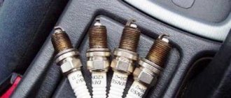
I just installed Denso spark plugs today.
by Adminrive Published 09.11.2016
- Comments 25
- Pingbacks 0
It goes on the ramp from the RTD.
Position 5: pressure regulator
Dima, but the return valve is not an RDT
Artyom, he also regulates the excess into the tank.
Dima, I changed it 2 times. The old one is much better. I don't even know what to look at
Artyom, what’s wrong?
Dima, the engine does not work stably, when you clamp the return line it works fine..it jerks, the consumption is increased, there is no traction..that seems to be all
The pressure in the ramp is less than expected
Artyom, you need to measure your blood pressure.
Artyom, RTDs rarely fail. Filter pump first
Dima, I heard about this. I changed everything in the filter... I changed the foam pump in the summer... it was the same, no improvement. Should I replace the entire fuel pump or some spare parts?
Artyom, fuel filter + pump. Measure how much pressure you have in the rail. For fuel systems with “return” (a pressure regulator is installed on the fuel rail, from which a tube goes back to the tank), a pressure of 2.7 atm is considered normal (when re-gasping it should jump up to 3 atmospheres). However, a pressure of 2.5 atm is also acceptable. If the pressure is less, then the fuel system is faulty. Pressure pulsation (0.2 atm) indicates a clogged coarse mesh (located in the tank with the fuel pump).
Artyom, the pump is not dismountable, just change it. But first measure the pressure in the rail. Then further
Dmitry, good article! We must try..
How to replace an RTD
The RTD is replaced in the following order:
- The pressure in the fuel system needs to be reduced; the nut securing the fuel pipe to the RTD is unscrewed.
- The bolt is unscrewed with a 10" wrench, which secures the guide tube of the direct oil level indicator, and the tube is removed.
- The bolts that secure the RDI to the ramp are unscrewed.
- The fitting is removed from the fuel rail and the RTD is removed.
- When installing a new regulator, it is recommended to lubricate the O-rings with gasoline.
In the future, do not forget to look at the fuel level sensor. When a large flow rate is detected, it is possible to suspect that an incorrect replacement was made, and it needs to be done more carefully.
conclusions
The fuel system check valve is an important component of this system, the failure of which can cause a lot of problems for the driver. This will be especially painful during movement. Therefore, it is worth using only high-quality fuel, and at the slightest sign of a malfunction, which were listed above, diagnosing the fuel system.
After all, the problem may lie not only in the valve, but also in other small parts. Diagnostics at a service station almost always reveals such faults, so do not forget about timely maintenance of the car, even if everything seems to be in good order. Good luck and easy travels!
Source
Fuel system features
"Seven" is an improved version of "Six". The latter, in turn, like all its predecessors, was distinguished by a carburetor power system. On the VAZ-2107 an injector can be used to supply the combustible mixture. This system is more reliable and efficient. The use of an injection power system on the VAZ-2107 made it possible to increase power by 5 percent and reduce fuel consumption by 7 percent.
An injection system is a whole complex of parts that combines the following elements:
- Control block.
- Sensors (mass air flow and lambda probe).
- Idle speed regulator.
- Fuel tank with adsorber valve.
- Pump.
- Filter.
- Injectors.
- Connecting tubes and hoses, as well as wiring.
A more detailed VAZ-2107 (injector) is presented below.
How it works? Fuel is supplied to the injectors under pressure. It is much higher than that of carburetor cars, but it is pumped not by a mechanical, but by an electric pump. On injection “Sevens”, a submersible pump is installed directly into the tank. On carburetor engines it is mechanical and is located in the engine compartment. Because of this, he often overheated on hot days.
A submersible pump pumps fuel out of the tank, where it enters the intake manifold through tubes under a pressure of 3 - 3.5 atmospheres. Gasoline first undergoes a purification procedure. For this purpose, a fine and coarse filter is provided (the latter is located directly in front of the pump). The amount of fuel that enters the cylinders is dosed by the injectors themselves using electronics. Excess gasoline flows through the fuel check valve into the tank. This element is two-way. It is indicated by the number 10 on the diagram of the VAZ-2107 fuel system (injector), which is presented above.
All processes for supplying and preparing the gasoline mixture occur automatically. As reviews note, the system is quite reliable and does not require adjustments, as is the case with a carburetor. But sometimes problems can arise with it. For example, the smell of gasoline suddenly appears in the interior of a VAZ-2107 (injector). What to do and why it is dangerous, we will consider further.
https://youtube.com/watch?v=PEMmSVodwLU
Pressure reducing valve in the oil system
Reducing valves are also used in the oil system and do not depend on the make of the car, because this is the most effective and simple way to relieve pressure. If it is missing or does not function, then the pressure in the system constantly increases, which leads to a decrease in the effectiveness of lubrication and the gradual destruction of the mechanism.
There are two similar elements in the oil system: the oil pressure valve and the oil pump. The first of them is located in the upper part of the structure and serves to lower the working fluid into the crankcase. It opens at a pressure of 0.40 Mn/m2.
As for the second, it is located in the lower section and is adjusted to the same pressure. If it exceeds this threshold, then the oil will simply begin to circulate in the pump system, gradually reducing the amount of liquid to the required threshold. The picture shows exactly this one, where you can see the location of the elements and the approximate path of the oil during operation.
It is extremely important to monitor the performance of these elements. A modern car has special oil pressure sensors that allow it to be controlled within the required limits. If it exceeds these values, then you should immediately check the operation of the reduction elements
If it exceeds these values, then you should immediately check the operation of the reduction elements.
Automatic choke without drive
The principle of this modification is based on the installation of an additional thermostat, which will provide control of the air damper. Many drivers are familiar with such a device as a thermostat, which is used on air filters. This device is designed to open the cold air damper by extending the rod when the temperature of the air flow increases.
To install this auto-suction pump on the carburetor with your own hands, you need to buy a thermostat for 8 and 9 and install it in a 0.5-inch tee. In addition, you will need fittings, a plug, a tee, a lever and a bracket. You don’t have to buy the last two elements, but make them yourself.
On both sides of the tee we screw fittings under the tube, which provides heating to the collector. The third outlet must be plugged, and then a hole must be drilled in the plug. After this, we cut a thread for the thermostat and screw it into the tee. We connect a lever to the resulting structure, which is connected through a cable to the air damper. We also screw the fasteners under the shirt.
When the engine is not warmed up and there is cold fluid in the system, the damper is closed. As the temperature of the antifreeze rises, the thermostat is activated, which moves the lever. The cable tightens and opens the valve. The air intake closes under the action of a spring when the engine cools down.