The phase sensor is used to determine the camshaft position angle. Moreover, this does not happen all the time, but only during a certain period of time. This information is quite important, as it allows you to make the vehicle operate efficiently and smoothly. To be specific, directly to the camshaft itself. This takes into account how the cylinder is placed in the engine. This ensures that fuel is supplied to the appropriate compartment, after which it is ignited.
Phase sensor for a VAZ 2112 car with 16 valves
Automakers strive to ensure that the operation of the vehicle brings safety, comfort and pleasure to the driver, and is also quite economical.
In this regard, cars are constantly being modernized. A modern car in its design has many different electronic devices and instruments that convert the indicators of the value specified for measurement and direct the data into the “electronic brain of the vehicle.” In turn, the machine’s ECU processes all the information received by it and, in accordance with the specified settings, gives a command to the electronic systems about the need for adjustments in operation. The camshaft position sensor (CPS) of the VAZ 2112 is one of the most critical elements of the car’s electronic system - it monitors the phases of operation of the cylinder-piston group and, as a result, influences the optimal operation of the internal combustion engine.
Video on the topic
Good publicity
The camshaft position sensor is a monitoring tool whose function is to analyze the position of the engine camshaft.
Based on the position of the crankshaft, the ECU calculates the required amount, as well as the time of fuel supply to the internal combustion engine cylinders, and the ignition timing is calculated.
In the design of the power unit, the indicator is installed on the cylinder head block and is additionally marked with appropriate markings. The original camshaft position sensor for the VAZ 2112 model is sold on the Russian market under article number 2112 - 3706040, the average cost of one part is 300 rubles.
It is important to know! This sensor is the only control and measuring device, without which proper operation further operation of the engine is impossible.
Purpose and principle of operation of the DPRV
The position sensor is designed to determine at a specific moment in time the position angle of the timing shaft. The obtained indicators are sent to the control unit, and after their processing, the operation of the automobile engine is adjusted to increase the efficiency and completeness of combustion of the combustible mixture. The result of the device is an increase in vehicle power, economic indicators and improvement of other characteristics.
DPRVs differ not only depending on the make and model of the car, but for different engines, for example, for eight- and sixteen-valve internal combustion engines.
To get an answer to the question of where the camshaft sensor (phase sensor) is located on a VAZ 2112 16 valves, just open the hood and carefully examine the internal combustion engine - it is located in the area of the timing shaft.
A rotor made of ferromagnetic material rotates together with the camshaft. Between the rotor and the permanent magnet is a Hall IC. When the protrusion passes by the DPRV element, the level of magnetic field strength changes, a voltage of a certain strength is induced and a signal is created, which is sent to the ECU for subsequent analysis.
How does it work
The Hall effect is an increase in potential difference when a conductor is placed in a magnetic field.
The VAZ 2110 phase sensor also works according to this principle.
For normal operation of the DPRV, a DC supply is required.
When the camshaft pulley rotates, its mark (protrusion) aligns with the end part of the DPRV. When the mark is opposite it, this means the position of the camshaft at which the intake valve of the first cylinder is open.
In this case, the potential difference in the semiconductor wafer DPRV increases. This signal passes through a secondary converter, which generates and sends a pulse to the electronic control unit. The secondary converter is built into the DPRV design.
Signs of DPRV failure
Over time, the phase sensor on the VAZ stops functioning correctly. Natural wear and tear is the main, but not the only reason for device failure. Signs of malfunction are easy to identify. It is enough to pay attention to how the car engine works. The first start of the internal combustion engine will be difficult and, instead of the usual “grabbing”, it will occur after a long period of torsion of the starter. During the operation of the vehicle, its power noticeably decreases, during acceleration “dips” in dynamics are observed, and instability in engine operation is periodically felt. In addition, motor fuel consumption increases significantly. This happens because the “electronic brain” issues commands for the fuel supply system and the moment of its ignition, based on incomplete data, thereby fuel injection is carried out under non-ideal operating conditions. Also, the “SNACK” signal will light up on the dashboard, which indicates the need to conduct a computer check of the vehicle systems. On some vehicles it is possible to lock the gearbox in one position.
These symptoms indicate problems that have arisen in the operation of the internal combustion engine, and the need for urgent comprehensive diagnostics to identify the exact cause of their occurrence.
When diagnosing a car with a computer, a phase sensor error will be indicated by one of the following codes stored in memory: P0300, P0340, P0341, P0342, P0343, P0344, P0365.
Symptoms of a problem
The question often arises about how to check the crankshaft sensor. The first sign of a breakdown of the device that monitors the crankshaft is the inability to start the car engine. In case of such problems, it is from this sensor that diagnostics and testing begin. But in addition to complete inoperability, there are several other signs of malfunction. One of them is a decrease in the rated engine power, as well as failures in the number of engine revolutions. In addition, problems may arise with the ignition system, since the crankshaft sensor is responsible for supplying the required amount of fuel fluid to the engine system. This is especially true for domestically produced cars, since the VAZ crankshaft sensor is not a standard of quality and reliability.
If any of the above symptoms are observed, it is worth scheduling a diagnosis. Otherwise, over time, replacing the crankshaft sensor may become inevitable. A timely detected malfunction will simplify car repairs and prevent unnecessary financial costs.
Reasons for sensor failure
A DPRV malfunction can occur for several reasons, and replacing it will not always solve the problem. The reasons why the device does not work may be the following:
- lack of contact between the device and the signal wire;
- the presence of moisture at the connection point of the DPRV;
- violation of the integrity of the wire, including its short circuit;
- incorrect power connection;
- axial timing runout;
- steel shavings on the device body;
- violations in the operation of the internal combustion engine control unit;
- incorrectly set gap.
Basis of operation of the ECM
This topic has already been covered and reviewed more than once, but it will have to be repeated a little. So, on injection cars, everything is controlled by a computer. It is he who supplies fuel to the cylinders through the nozzles and ignites the working mixture with a spark formed on the spark plugs. He does this according to the program embedded in his memory. It's called "firmware".
But to execute this program correctly, very accurate data is needed. The electronic control unit (ECU) must know exactly the following parameters:
- Crankshaft position.
- Camshaft position.
- The amount of air supplied.
These are the three basic units required for the "brain". And sensors are used to deliver this information necessary to the ECU.
Why is it called a phase sensor
The camshaft of the Priora engine, like any other car, is responsible for the timely opening of the intake and exhaust valves in the cylinder head. This process is called gas distribution. There is a definition - a four-stroke engine. These are exactly 4 phases:
A carburetor engine, so to speak, does not distinguish between these subtleties. Fuel flows into the cylinders constantly. And the advantage of the injector is that the injection of the working mixture into the chamber occurs exactly at the right moment.
The fact that this moment has arrived and the Priora engine has entered the desired phase is reported by the camshaft position reader.
Design and location of the phase sensor
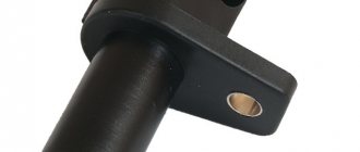
Like most such devices, it uses the Hall effect. Therefore, it is based on a semiconductor, which, under voltage, changes conductivity depending on the approach or removal of metal. This element is housed in a spindle-shaped plastic case. At the very end. On the opposite side there is a connector for connecting the Priora wiring chip.
Since the Priora is currently equipped with 8 and 16 valve engines, the phase readers on them are accordingly different.
Where is the phase sensor located?
On an engine with 8 valves, this sensor is installed in a special glass at the end of the cylinder head. Where the camshaft end comes out. From the gearbox side. It reads the signal from a special protrusion on the shaft.
The Priora phase sensor for 16 valves is installed on the opposite side. Where the shaft drive gears are located. Everything works differently here. It looks like a Hall reader for an electronic ignition. On the camshaft gear installed on the engine on the radiator side, a metal “skirt” is attached from the inside. It fits into the sensor slot and has a control slot. The sensor “reads” it, sending a signal to the Priora ECU. The device itself is attached to the head body with two bolts, and accordingly has two mounting lugs near the connector.
Symptoms of malfunction and checking the phase sensor
Like any fuel-injected car. In the Priora, a malfunction is primarily indicated by the appearance of a light signal from the Check Anger lamp.
But there are also tangible signs of a malfunction of the Priora camshaft sensor. Unpleasant jerking of the car appears when accelerating. And most importantly, the startup time increases significantly. That is, if the device is working properly, the starter only needs to give a small push to start the engine. And if this malfunction exists, then you have to make several revolutions of the crankshaft to start.
It can only be checked using computer diagnostics. Only she will tell you whether the phase sensor is 100% working or not. Sometimes this information is provided by an additionally installed on-board computer with a display.
Useful video about the Priora phase sensor:
How to check the phase sensor
Before taking measurements and performing replacement work, it is worth visually inspecting the position sensor and checking the wires for integrity. If, as a result of the inspection, no malfunctions that could affect the operation of the device are identified, it is necessary to check the DPRV.
To find out whether the phase sensor is working or not, you will need some knowledge and ability to use a multimeter. Diagnostics can be carried out in several ways, so as an example, we will consider diagnostic methods for various DPRVs.
- Two-wire device. Operating procedure:
- start the internal combustion engine;
- switch the voltage measurement mode on the multimeter to the AC voltage position;
- Connect both wires from the electrical meter to two different terminals on the camshaft sensor. If the voltage fluctuates up to 5 V, then the part is serviceable; if there is no voltage, then replacement is necessary.
- Three-wire device. Operating procedure:
- start the internal combustion engine;
- switch the electrical measuring device to constant voltage mode;
- connect one contact of the multimeter to the black wire on the part, and the second to its power wire. If the voltage indicator is missing, then replacement is made. For a specific car model, the voltage value is indicated in the instruction manual.
The part is non-repairable, therefore, if it is found to be faulty, it is replaced with a new one.
Replacement, Connection diagram, How to remove
The ignition does not turn on on the VAZ 2112? One of the causes of the disease may be in the ignition switch. Don't rush to replace the ignition switch with a new one, first try checking it yourself.
Table of contents
Replacement Connection diagram (pinout) How to remove
Replacement
First, remove the negative terminal on the battery and remove the lower casing under the steering wheel.
1. Disconnect the ignition switch wiring harness connectors.
2. Having rested the chisel blade against the edge of the head of one of the bolts, lightly hit the chisel with a hammer to loosen the bolt.
3. Using pliers with narrow jaws, remove the bolt.
4. Similarly, unscrew the three remaining bolts securing the ignition switch.
5. Remove the lock mounting bracket...
6. ...and the ignition switch itself from the steering column.
Installation
1. Before installing the ignition switch, insert the key into it and turn it to position I (“on”) so that the latch of the steering shaft locking mechanism is pushed into the lock body.
2. Install the ignition switch with mounting bracket on the steering column and hand-tighten the new mounting bolts.
3. Having removed the key from the ignition switch, we check the operation of the steering shaft locking mechanism. If the steering shaft does not lock after a full turn of the steering wheel, adjust the position of the ignition switch on the steering column so that the lock latch can fit into the groove on the steering shaft.
4. After making sure that the locking mechanism works, use a 10 mm spanner to tighten the bolts evenly (crosswise, half a turn) until their heads come off.
Connection diagram (pinout)
Connect and install the ignition switch in the reverse order, having previously recessed the tongue of the anti-theft device; to do this, you need to insert the key into the lock and turn it from position 0.
How to remove
Prepare the vehicle for operations. Remove the key from the ignition. Disconnect the cable from the negative terminal of the battery. To do this, simply use a wrench to loosen the terminal fastening nut and remove the wire. There is no need to remove the positive cable from the battery terminal.
Remove the steering wheel, steering column trim and steering column switch assembly. To do this, use a Phillips screwdriver to unscrew the four bolts securing the steering column trim and unscrew the three screws screwed into the steering column bracket. Lower the steering column adjustment lever all the way down and remove the lower casing. Then lift the lever all the way up and remove the upper casing.
Disconnect the connector of the wires coming from the steering column switch block. To remove the right steering column switch, squeeze the latches (top and bottom) with your fingers and remove it. Remove the left steering column switch in the same way. To remove the steering column switch connector, loosen the pinch bolt using a socket, disconnect the horn wires and remove the connector itself.
To remove the steering wheel, use a flat-blade screwdriver to pry up the horn button cover and remove it. After this, use a Phillips screwdriver to unscrew the two screws securing the steering wheel cover and remove the cover. Then remove the moving contact of the audio signal by unscrewing the three screws securing it and disconnecting the wire
Using a 24mm socket, unscrew the steering wheel mounting nut. Do not remove the nut completely. Using a rocking motion, pull the steering wheel toward you to remove it from the shaft. If it breaks off the shaft, a non-removed nut will protect your face from injury. If the steering wheel is very tight, have an assistant pull the steering wheel. At the same time, simultaneously strike with a hammer through a soft metal drift at the end of the steering shaft.
Disconnect the steering wheel slip ring wire. Then remove the ring itself by unscrewing the three screws securing it with a Phillips screwdriver. After this, remove the steering column switch block interlocked with the ignition switch (lock).
Replacing the DPRV
Replacing the phase position sensor of a VAZ 2112 16 valves is not difficult. Fastening to the internal combustion engine is carried out with two bolts, which are unscrewed with a 10mm socket wrench. Let us consider the replacement process step by step.
- We de-energize the car by removing the ground from the battery.
- Remove the terminal block from the sensor.
- Unscrew the fastening bolts with a socket wrench.
- Carefully pull the part and remove it.
- We install a new DPRV and carry out the work in the reverse order.
For proper operation of the position sensor after replacement, the mounting gap must be within 0.5–1.2 mm.
The camshaft sensor for a VAZ is inexpensive, but if you operate a car with a faulty device, this will lead to more complex and expensive breakdowns to repair.
conclusions
Replacing the phase sensor (camshaft position) of the VAZ-2112 16 valves is quite easy. It is much more difficult to determine its malfunction, since there are many indirect reasons, but there is only one direct reason - direct diagnosis. The only thing that will please the car owner is that the part is one of a kind and there are no analogues.
We have a VAZ 2112 car with a 16 valve engine under repair, on which the phase sensor needs to be replaced. We'll show you how to do it yourself quickly and correctly.
The phase sensor is responsible for fuel injection; if it fails, the injectors inject fuel simultaneously, regardless of where the piston and camshafts are located. Symptoms: lumbago, unstable idling, increased fuel consumption, the Check Engine lights up on the instrument panel, and error P0340 is displayed during diagnostics. Before replacing, it is necessary to perform diagnostics, first of all, check all the wires going to the sensor.
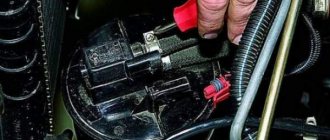
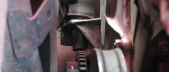
The phase sensor is located near the intake camshaft pulley. To replace it, first of all, remove the negative terminal from the battery, then unscrew and move the adsorber tank to the side:
Using a long spanner, crawl over the alternator belt and unscrew the two bolts:
There are no problems with the nearby bolt, just don’t drop it to the bottom. Access to the second one is more difficult; you have to make a lot of movements with the key over a small radius. After removal, inspect the phase sensor for mechanical damage:
If it is damaged, there are scuffs, it is necessary to remove the timing belt cover and eliminate all defects on the drive disk that damage the sensor. In our case, it is intact; its electronic part has failed. To make it easier for us to install a new phase sensor, we use plasticine to fix the far bolt in the hole so that it does not fall:
We tighten everything in the reverse order. Other online instructions for replacing the phase sensor suggest removing the generator, intake manifold, and even headlights and bumper. The article number of the original sensor is 2112.3706040-01; its analogues are VS-CM 0112, CMPS-LA2112, 4102.3847.
The components of the camshaft are elliptical cams, each of which acts on its own personal valve, that is, the task assigned to the camshaft is to control the exhaust and intake valves. Although it is driven by a belt drive from the crankshaft, its speed is half the speed of the crankshaft.
Unfortunately, it is impossible to determine which phase of engine operation is currently in operation only by the position of the crankshaft (the compression stroke with the accompanying ignition of the fuel mixture or the moment of exhaust gas emission), then the camshaft position sensor helps the electronic control unit determine the desired phase gas distribution mechanism. The photo below shows how the camshaft acts on the valve: The camshaft cam (1), rotating, acts on the valve (4) through the pusher (2) and the spring (3), the valve seat (6) opens and the exhaust gas moves through the channel (5). gases/fuel mixture from/to the chambers/combustion chamber (7).
Operation of the gas distribution mechanism
Principle of operation
In the domestic automotive industry, sensors that help the engine control system determine the desired phase of the gas distribution mechanism began to be used in contactless ignition systems of carburetor “eights”. It was installed in a distributor, and its operation was also based on the so-called Hall effect. This sensor removes and transmits to the commutator the signal received from a metal shutter that has one slot, which is attached directly to the crankshaft gear (1).
The relative position of the metal disk and the phase sensor
That is, the curtain itself (2) is constantly located between the magnet and the sensor (3) that reads its signals, thereby preventing it from reading the magnetic lines. The slot (4) serves to generate and supply an impulse from the sensor to the electronic control unit (switch). The presented design is designed in such a way that the phase sensor informs the commutator with a pulse precisely at the moment when the compression stroke occurs in the first cylinder. Pulse parameters: slot opposite - the voltage is almost zero, slot to the side - the voltage is almost equal to the voltage in the on-board circuit.
Sensor differences
The above-described design is called slotted and is used in the control system of a 16-valve engine on a VAZ 2112/2110. On a VAZ 2115, replacing the camshaft sensor is somewhat different, since VAZ engines of the 2111 and 21214 series are equipped with end-type phase sensors. It also works on the principle of the Hall effect, only its design does not use a slot, but a special setting mark. In this case, the pulse passes when the tag approaches the phase sensor. Since the distance between them is much smaller than between the sensor and the camshaft itself, when approaching, the magnetic field of the sensor changes, which contributes to the formation of a synchronizing pulse. On engines of the 2111 series, this mark is located on the camshaft itself, and on the 21214 series - on its drive pulley.
Attention! The pulse formation on the 21214 series engine occurs at the top dead center of the fourth cylinder, which falls on the compression stroke.
Symptoms of a problem
Most often, malfunctions in the camshaft timing sensor occur due to simple contamination of the contacting surfaces and a break in the power circuit, in which case:
- The “CHECK” indicator light is on;
- The engine starts only after prolonged rotation by the starter (about ten revolutions);
- Power drops slightly with a simultaneous increase in fuel consumption (problematic to determine);
- Deterioration in dynamics, dips appear during acceleration.
All VAZ-2112 sensors 16 valves and their location: diagram and description
The efficient operation of the injection engine is ensured by a set of sensors. They all connect to the ECU. Lada hatchbacks of the 2112 family were produced only with injection engines, and two varieties of these internal combustion engines are 16-valve. We will talk about them further. All VAZ-2112 sensors, their location and appearance will be shown in the photo.
The excess oil pressure sensor, which is not connected to the ECU, is shown in the video.
Checking the DPKV for serviceability
Also, the motorist should not forget to measure the clearance between the synchro disk and the sensor before dismantling, which cannot go beyond the size of 0.6-1.5 mm. If there are no mechanical damage such as scratches, dents, or damage to the material structure, the sensor is checked using other measuring instruments:
checking with an ohmmeter. In this case, it is necessary to measure the resistance of the sensor winding
Since the standard value of this indicator, set by the manufacturer, ranges from 550 to 750 Ohms, going beyond the specified limits indicates the malfunction of this device, which is important for the correct operation of the car - which means it is faulty. It is worth noting here that the manufacturer still allows a slight discrepancy in resistance with the nameplate values, but in any case they must correspond to the data specified in the machine’s operating instructions; checking with a voltmeter, inductance meter and transformer
This method is more complicated, but more effective - the resistance is measured with the same ohmmeter, after which the inductance is checked (should be from 200 to 4000 millihenry), with a sensor winding voltage of 500 Volts. Next, you need to measure the resistance with a megger and make sure that it does not exceed 20 MOhm.
If the sensor still does not pass these tests, it must be replaced. During this procedure, it is necessary not to forget about the distance between it and the synchronization disk regulated by the manufacturer, as well as alignment with the marks on the crankcase that were made on the previous device. Before installing a new sensor, be sure to check it, since even if all installation procedures are followed correctly, it may not work properly.
A new DPKV is checked according to the same procedure as a supposedly faulty one, and based on the test results, the device can be installed instead of the previous one or rejected. When installing, the bolts are tightened with a torque of 8 to 12 Nm. However, in any case, before carrying out all the actions to replace a rather expensive and hard-to-reach component, you should definitely make sure that it is the one that has failed, because cars produced by our automotive industry can often bring unpleasant surprises.
First way to check
In this case, you will need an ohmmeter with which you will replace the resistance on the winding. According to the manufacturer's standards, the indicator ranges from 550 to 750 Ohms.
It's okay if your numbers are slightly different from the norm. If the deviations are serious, you will definitely have to replace the sensor.
It should be noted in fairness that the crankshaft position sensor on VAZ 2110 models rarely breaks down. Among the main reasons for its failure to function normally is the accumulation of dirt, mechanical damage, as well as banal factory defects.
Features of testing on other cars
As for other cars, for example, VAZ-2109 with an injection engine, VAZ-2112 and VAZ-2114, their check is carried out identically to the VAZ-2110 car.
It is noteworthy that for VAZs, when checking the resistance of the crankshaft sensor coil, an additional check can be carried out.
But to do this, the multimeter must be switched to voltmeter mode with a measurement limit of 200 mV.
Then connect the probes to the DPKV terminals and pass them with any metal object, for example, a screwdriver, at a short distance from the core.
If the sensor is working properly, it will react to metal, the multimeter will show voltage surges on the display. The absence of these bursts will indicate a faulty element.
As for a car like the Reno Logan, the difference from the VAZ in this car comes down to slightly different readings of the resistance of the sensor coil when measured with an ohmmeter.
A working Logan DPKV has a normal resistance of 200-270 Ohms.
For Daewoo Lanos, the coil resistance should be in the range of 500-600 Ohms.
But on the ZMZ-406 engine, installed on Volga and Gazelle cars, the normal coil resistance is in the range of 850-900 Ohms.
Second method
Here you will need a voltmeter, a transformer and an inductance meter. It is advisable to measure resistance under compact temperature conditions.
Once the ohmmeter readings are obtained, arm yourself with an inductance measuring device. Normally, the device should show from 200 to 4000 units (millihenry).
A megger measures the resistance when the crankshaft position sensor winding is powered at 500 volts. Under normal conditions, the readings will be no more than 20 MΩ.
Understanding the oxygen sensor
It is necessary to determine the sensor articles not by the engine model or even by Euro standards, but only by the ECU unit.
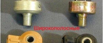
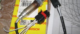
Types of oxygen concentration sensors (OCC)
The number of oxygen sensors can be two or one - it all depends on environmental standards. AvtoVAZ also used two types of sensors - 0 258 005 133, 0 258 006 537 (BOSCH part numbers). The first of them are compatible with BOSCH M1.5.4, MP7.0 and January 5.1 controllers. Newer sensors were connected to the BOSCH M7.9.7 ECU (January 7.2). The two different types of sensors differ even in appearance.
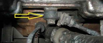
The ECU unit in “Dozens of VAZs” is located under a plastic cover. It is located near the front passenger's foot.
The red arrow marks the first, that is, the main sensor. The top photo corresponds to engine 21124 (1.6 l).
Sensor locations (21124 and 21120)
VAZ-21120 engines (1.5 l) could meet the Euro-3 standard, and then an “extended” catalyst was welded behind the main sensor. The second sensor was located behind it, that is, behind the “can”. Let's clarify:
- The Euro-2 standard corresponds to a design with one sensor (main);
- During the transition to Euro-3 standards, a second sensor was added (blue arrow).
By the way, the 24th engine can meet Euro-4 standards.
Examination
Before you can check it, you first need to get to it. And the device is located in a not very convenient place on the engine. So be prepared to spend some time on this.
Now to the question of how to check it. Let's look at the two most common situations, but first, let's remove the element.
- The sensor is removed with a 10 mm wrench;
- Be sure to make special marks on the crankcase and sensor before removing. This will allow you to return it to its original place, or install a new regulator in the correct position;
- If there is no external, visible damage to the crankshaft sensor, then you need to use a multimeter;
- Don't forget to measure the distance between the sensor and the timing disk. In the normal position, the gap ranges from 0.6 to 1.5 millimeters.
First way to check
In this case, you will need an ohmmeter, which you will use to replace the resistance on the winding. According to the manufacturer's standards, the indicator ranges from 550 to 750 Ohms.
It's okay if your numbers are slightly different from the norm. If the deviations are serious, you will definitely have to replace the sensor.
It should be noted in fairness that the crankshaft position sensor on VAZ 2110 models rarely breaks down. Among the main reasons for its failure to function normally is the accumulation of dirt, mechanical damage, as well as banal factory defects.
Second method
Here you will need a voltmeter, a transformer and an inductance meter. It is advisable to measure resistance under compact temperature conditions.
Once the ohmmeter readings are obtained, arm yourself with an inductance measuring device. Normally, the device should show from 200 to 4000 units (millihenry).
Main set of sensors for 16-valve VAZ-2112 engines
The ECU must control many parameters at once. The most important information will be the position of the crankshaft. You can turn off all sensors except the DPKV, and this will not lead to the engine stopping.
Sensors connected to the ECU
Let's list all the elements one by one:
- 15 – DTOZH. A resistor screwed into the thermostat housing. The temperature of the antifreeze is determined;
- 17 – DPRV, also known as DF (phase sensor). The operating principle is the Hall effect. The position of the camshaft is controlled. Check it out here.;
- 20 – TPS. Resistor fixed to the throttle assembly 19. The angle of deflection of the throttle valve is measured;
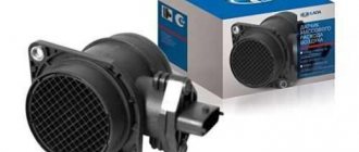
- 21 – Mass air flow sensor. Sensor connected to the filter housing. Controls air flow; the main signs of its malfunction are discussed here;
- 22 – IAC. Not a sensor, but a regulator (electromagnet). Used in idle mode. About its testing and diagnostics here. About replacing the IAC here.;
- 24 – lambda probe or oxygen sensor (see above);
- 25 – speed sensor. Fixed in the gearbox slot. Operating principle – Hall effect;
- 26 – DPKV. Electromagnetic sensor. The position of the crankshaft is controlled;
- 27 – DD (knock sensor). A piezoelectric element mounted on the outer wall of the cylinder block.
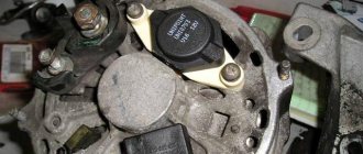
Let's take a look at how all the elements look in real life. Shown are pictures of VAZ-2112 sensors (16-valve internal combustion engine).
Each element will be easy to find under the hood
Everything said above is true for two engines at once - for units 21124 and 21120 (1.6 and 1.5 l).
You cannot unscrew the DTOZH sensor without draining the coolant. And to disconnect the sensor means to disconnect the connector, but not to dismantle the sensor itself.
Where is which sensor located - engine compartment diagram
Let's look at another picture.
Engine compartment and engine 21124
It is important to understand where the following elements are located:
The location of the phase sensor is indicated in the previous chapter.
Never unscrew the speed sensor. It will be difficult to install it in a way that maintains a seal.
Location of the DPRV on the engine
To perform a camshaft position sensor test, you need to know where it is located. As a rule, on eight-valve engines the DPRV is usually installed at the end of the cylinder head. On sixteen-valve engines it is also installed on the cylinder head, usually near the first cylinder.
Read more: Set up HBO 2nd generation yourself
As for popular domestic VAZ cars, their owners call such units phase sensors. Their arrangement in these engines is similar. So, on eight-valve engines, the sensor is located on the left side of the cylinder head (when looking in the direction of travel of the car). On sixteen valves - on the right front part of the engine. In the latter case, the sensor is not directly visible; its position can only be assessed using suitable signal and power cables. The VAZ 2114 phase sensor is mounted near the air filter, near the cylinder head.
Articles
For oxygen sensors, the designation 21120-3850010 was first used. Then an article appeared with the numbers 1118 (see photo). It appears to be a new type of sensor. It will be easier to use BOSCH articles.
Exhaust system of VAZ-21120 engine
We list the article numbers of the remaining sensors:
- Mass air flow sensor (21124 or 21120): 21083-1130010-01, -10, -20;
- Mass air flow sensor (motor 21120 with ECU January 4.1): 2112-1130010, -01;
- TPDZ : 2112-1148200;
- RXX: 2112-1148300-02;
- DPKV : 2112-3847010, -01, -03, -04;
- DTOZH : 2112-3851010, -01, -02, -05;
- Speed sensor : 2110-3843010-13, -18;
- DPRV : 2112-3706040, -02, -03;
- DD: 2112-3855020, -01, -02, -03;
- Oil pressure sensor: 2106-3829010, -01, -02;
- Antifreeze level sensor : 2110-3839310-10, -11, -12, -13, -14;
- Coolant temperature gauge sensor: 2101-3808600, -02, 2106-3828010.
The last three sensors are not connected to the ECU. However, a rough road sensor (2123-1413130) can be connected. It affects the operation of the engine, although it is attached to the body.
Engines with ECU January 4.1 do not have oxygen sensors.
In general, on VAZ-2112 hatchbacks, sensors may be different from those indicated in the list. But then we are talking about an 8-valve engine. And everything that we indicated applies to 16 valves, here is a diagram of this engine.
Source
Removing the sensor in three steps
To remove the phase sensor, first turn off the ignition. The sensor connector is easy to disconnect: it is secured with a plastic tab.
Sensor location and installation
With the connector disconnected, use a 10-point socket wrench to remove the two bolts holding the sensor in place (see photo). Then the sensor body is pulled out from under the casing, pressing it against the head.
When installing, the clamping force of the fastener should be 8-10 N * m.
Here we showed how the sensor is removed on the 21120 (16v 1.5) engine. For the VAZ-21124 engine, all stages will be the same. If you look at the car connector, you can see three terminals. Their purpose is illustrated by the figure.
This is the sensor body, not the car terminal block
There is a desire to measure the voltage between the two terminals on the right. If you don't start the engine, it will start.
With the ignition on, connect the negative probe to the negative terminal of the battery. Measure the voltage separately on the right and on the middle contact: you should get “0” and “+12”.
The phase sensor has failed: how to determine
Like any other part, the phase sensor can fail. There are many reasons for this. Quite often the part simply wears out. It is not difficult to identify this problem. Just take a close look at how the car works. He himself will tell you about his breakdown.
If we talk about obvious signs, they will appear after you turn on the ignition. The engine will turn the starter for a few seconds. After this, the usual starting of the engine and activation of the ainge check will not occur.
Since the sensor will not transmit the necessary readings to the electronic engine unit. The engine will operate only on what the ignition indicates.
Another symptom that is often encountered is a faulty diagnostic system.
It allows you to independently determine the condition of the vehicle. In this case, it will also fail and will not reproduce any data, since it will not be able to perform its main function. It is also worth paying attention to the level of engine dynamics. It will decrease significantly. At the same time, when the car accelerates, dips will appear. They indicate that the sensor has failed.
The most obvious sign is the light on the instrument panel. It will light up with the words “CHEK”. Which means “check” in translation. This signal should not be ignored. It is necessary to immediately react to it and carry out the necessary manipulations.
Another breakdown signal is error code P0340. Its decoding can be found in the device operating book. It indicates that a sensor error has occurred.
Soulemil › Blog › Crankshaft position sensor VAZ 2110 - how to find a fault and replace it?
A modern car consists of many parts, each of which performs its own important function. Information about the condition of the engine and other components is transmitted by various sensors, but the VAZ 2110 crankshaft sensor performs work that is unusual for these devices. Purpose of the VAZ 2110 crankshaft position sensor Crankshaft position sensor
If the engine of a 9th or 10th series car refuses to start, any driver immediately begins to check the power and ignition system, and when it comes to contacting a car service center, they say that the DPKV has failed (this is what the abbreviation for the full name of the sensor looks like ). The bewilderment of car owners is dispelled when they find out that this is the only sensor without which the engine will not work.
The crankshaft sensor of the VAZ 2110, as well as on many other cars, does not perform a monitoring function, but synchronizes the phases of fuel injection and supplying an impulse to ignite the combustible mixture in the combustion chamber
Obviously, removing such an important attribute from the design makes it impossible for all systems to work harmoniously
In its operation, the sensor uses the principle of electromagnetic induction, and reads the necessary “information” from the generator drive toothed pulley, in the immediate vicinity of which it is installed. Disconnect the sensor Unscrew the mount Remove the sensor VAZ 2110 crankshaft sensor - faults and their diagnosis Crankshaft position sensor bracket
Considering that the role of the DPKV in the operation of the engine is very significant, in the event of its malfunction, a variety of “surprises” can be expected. A completely failed sensor will definitely prevent the engine from starting. Other manifestations of sensor problems include:
unstable operation of the engine at idle; decrease in power; increase and decrease in the number of crankshaft revolutions (spontaneously); detonation when the load increases; intermittent starting.
For a device such as the VAZ 2110 crankshaft sensor, faults come down to two types:
damage to the windings and parts of the sensor itself; violation of the integrity of the wire and the quality of connections in the circuit.
The PCV sensor itself is very simple in design and rarely fails. A crankshaft position sensor error or breakdown can be caused by reasons such as: manufacturing defects, mechanical damage, significant contamination. The first two reasons do not depend on the driver, and the car owner can monitor the cleanliness under the hood.
In addition to the fact that the engine compartment is always under the influence of many destructive factors, such as temperature changes, small stones and dust flying from the roadway, significantly adding to the problems of oil leakage. If it is discovered that there is a leak of engine oil in any place, especially in the area where the sensor is installed - on the oil pump body, it must be repaired immediately. The contacts of the sensor wire connections must always be clean and protected. The wire insulation should not be damaged or have exposed wires. How to check if the VAZ 2110 crankshaft sensor is working?
Considering that a crankshaft position sensor error or complete failure has very similar symptoms to many other breakdowns, you should understand how to check its condition. You can only verify that the DPKV is working if you remove it. This is not at all difficult to do, you just need to follow these steps:
turn off the ignition; remove the terminal connector with the wire from the sensor; unscrew the only screw holding the sensor to the oil pump cover; remove the sensor.
To check, you need to have an ohmmeter and check the resistance of the windings. If the instrument readings differ from the required 550-570 Ohms, it means the crankshaft sensor is faulty. You should not try to repair it, as this device cannot be repaired. The only way out of the situation is to replace the crankshaft sensor of the VAZ 2110. The cost of the DPKV is low, installation does not require much time and skills, especially since the car without it still remains motionless. If the device shows that the resistance of the sensor windings is normal, then the breakdown should be looked for elsewhere. How to replace the crankshaft sensor?
Installation, as well as removal of the PCV sensor, is done quickly and without difficulty. Before proceeding with installation, the installation site should be cleared of dust and dirt. Next, simple steps are performed: the new sensor is inserted into its regular place; the fastening screw is tightened; The connector with the wire is put on. At this point, the replacement of the VAZ 2110 crankshaft sensor is completed and you can start starting the engine.
Checking the Hall sensor and replacing it
The Hall sensor is one of the most important elements of the contactless ignition system for gasoline engines. The slightest malfunction of this part leads to serious problems in the operation of the motor.
Therefore, in order to avoid diagnostic errors, it is important to know how to check the Hall sensor and, if necessary, to be able to replace it. We divided this material into two parts: theoretical (purpose, design and principle of operation of the Hall sensor) and practical - signs of malfunction, verification methods and replacement methods
At the end of the article, watch the video instructions on how to replace the Hall Sensor yourself.
And before checking the Hall sensor for malfunctions, let's understand its purpose and operating principle.
Lada 2110 21114 1.6 8V 2007 MT › Logbook › Error P0340 2110 phase sensor DF, DRV
A check was displayed, after connecting the laptop the program showed an error - P0340 for the phase sensor or as it is also called the camshaft sensor. I decided that the sensor had died and replaced it with a Kaluga one purchased on the market. The error went away, I sighed. About a month later, the same situation, again an error in DF. I removed the terminal from it and saw that the positive contact i.e. the middle one has oxidized. I picked up contact cleaning aerosols from the market, treated it, and let it dry for 15 minutes. And since the contacts themselves were already approaching, I decided to press them a little with a screwdriver, somehow it was possible... but not of good quality due to the design of the contact itself. I put the sensor back and decided to observe. I started it, drove about 50 meters, the check light came on, I think everything is repeating itself again, after driving a little more, the car warmed up to operating temperature and the error disappeared, I think miracles! After traveling for a couple of days, the situation is the same. I think DF has given a long life again. I bought a new sensor, again from Kaluga, but in a different market. I installed it, the error went away, but I think I found the problem, as a version - in the oxidized contact, because of this, the sensor died, and the error went away after the engine warmed up, because along with the warming up, both the sensor and the contact warmed up. After riding for three weeks this time, this error came to me again