03/03/2022 8,979 Transmission
Author: Victor
The ZIL 130 gearbox is a unit that differs from the gearbox in other cars. When getting behind the wheel of this car, the driver must know how the gears are switched and what the operating pattern of the unit as a whole is. We will talk about the design and repair, as well as care of the transmission of domestic trucks below.
[Hide]
How does the ZIL 130 gearbox work?
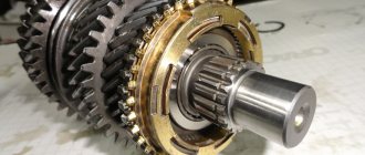
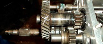
First, let's analyze the gearbox structure of the ZIL 130 car. These cars are equipped with five-speed three-code manual transmissions. The unit has five speeds for moving forward, as well as one gear for moving in reverse. The transmission uses two inertial-type synchronizing devices to engage gears 2 and 3, as well as 4 and 5. A primary shaft, called the drive shaft, is installed in the crankcase of the unit on bearing elements. It is assembled with a helical gear and a ring gear for engaging gear 5.
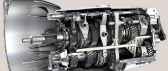
Transmission design diagram for ZIL
A cylindrical roller bearing device is mounted in the shaft bore. A secondary pulley is placed on this part with its front side. The drawing shows how an intermediate shaft is mounted at the bottom of the crankcase, where another gear is fixed, number 1. It is located in mesh with the same gear, marked number 4, only located on the drive shaft. Three more similar elements are installed on the intermediate pulley. They are marked with numbers: 17 for reverse, 15 for gear 1.
The splined elements of the secondary shaft have a spur gear number 11, it is designed to activate first and reverse speeds. The gear carriages of synchronizing devices 5 and 9 are also located here. Helical gears mounted on the secondary shaft are used to activate the second speed (item number 10), third (item number 7) and fourth gear (gear 6). They are installed so that they are in constant engagement with the same elements of the intermediate shaft. An axis numbered 13 is rigidly fixed at the bottom of the unit crankcase; a block with straight-cut rear speed gears (number 12 in the diagram) is mounted on this element using cylindrical roller bearing devices.
The large gear on the block is installed so that it works in constant engagement with element 17 mounted on the intermediate shaft. The internal component of the crankcase is filled with consumables - transmission lubricant. This part is closed with a protective cover into which the gear shift mechanism is mounted.
Switching circuit
To understand how to switch and adjust speed in a car, check out the photo diagram.
Selector switch diagram for ZIL gearbox
Transmission lever
This is the last component in the gearbox assembly (its characteristics from the ZIL-130 are discussed above). The procedure is as follows.
- The selector housing is installed on a special machine or in a vice.
- The locking part is placed in the slot on the crankcase of the unit, a cover is put on the selector, and it is placed in its place.
- The ball surface is treated with a layer of lubricant. A spring is inserted behind the crankcase studs, which is installed together with the ball element support.
- Assemble the intermediate lever of the first and second speeds.
- The handle is secured using a nut, and the gasket is secured to the gearbox cover using sealant.
- Finally, the intermediate part is installed in a special slot on the rod head. The second analogue is placed in the groove of the fork. The lever is secured to the body using special clamps with spring-type washers.
How do synchronizers work?
Now let's look at how speeds are switched in the ZIL 130 kinematic gearbox and the principle of operation of synchronizers and gears. When the driver reaches first gear, gear number 11 begins to move along the splines and engages with element number 15 of first gear, located on the intermediate shaft. From the input shaft, through constant mesh gear parts marked with numbers 4 and 1, and then to devices 15 and 11, torque is transmitted to the secondary pulley. The gear ratio in this case is 7.44.
When second speed is activated, the clutch located on synchronizer 9 engages the internal teeth of gear number 10 of gear 2. As a result of the fact that this component is already engaged with part number 16 on the intermediate shaft, torque will be transmitted carried out from the input shaft through gear elements 4 and 1, as well as 16 and 10. The transmission of force to the secondary shaft will also be facilitated by the gear coupling of the synchronizing device. The gear ratio corresponds to 4.1.
When the driver activates gear 3, the clutch of this device leaves the engagement with gear element 10 and moves along the splines, as a result of which it interacts with the teeth of gear 7. At this moment, it is already in engagement with part number 18 of the third speed of the intermediate unit. The force from the primary pulley will come through gear parts numbered 4 and 1, as well as through elements 18 and 7 of the third speed. Through the gear coupling of the synchronizing device, torque is supplied to the input shaft. The gear ratio is 2.29.
Find out about the repair of the ZIL gearbox from the video filmed by the channel All about technology and more.
When the driver engages fourth gear, synchronizing device 5 begins to work. The clutch of this mechanism begins to move under the influence and engages with the teeth of gear number 6. At the time of interaction, it is engaged with gear number 19 of the fourth speed on the intermediate shaft. The force is transmitted from the primary pulley through the gear parts to the secondary shaft. The gear ratio parameter is 1.47.
When gear 5 is engaged, the synchronizing clutch leaves engagement with gear number 6 and, moving along the splines, begins to interact with the internal teeth located on the fourth part of the input shaft. As a result, two shafts - the drive and the secondary - form a single structure that transmits force to the driveline of the vehicle. As for the reverse gear, when it is activated, a special gear-carriage, marked with number 11, comes into operation. It begins to move along the splines to the right and interacts with the gear element numbered 12, which is located on a special block. At the moment of engagement, the larger element of the mechanism is already in engagement with part 17 on the intermediate pulley. The force is transmitted from the drive shaft through gear devices 4 and 1, 17 and 12', 12'' and 11 to the secondary pulley. During the transmission of torque, the direction of rotation changes.
Signs of breakdown
There are several signs of wear on the synchronizer and other internal parts. The following can be distinguished:
- the transmission switches off automatically while the vehicle is moving;
- the appearance of a sharp noise when switching occurs;
- the driver has to make an effort to engage the gear.
Many people complain that they hear strange noise when the gearbox is working and the car is in motion. This sign indicates wear or breakage of the cone. Under increased loads, bending and deformation of the blocking ring may occur.
There is another serious problem that requires urgent repairs. It consists of spontaneously switching on the gear. This problem may be due to wear on the clutch or gear. If the gear is engaged with force, it is necessary to check the functionality of the synchronizer. The mechanism has a simplified design, so it can be repaired and restored. But to ensure safety, it is recommended to install a new synchronizer.
To extend the life of the synchronizer, you must perform the following actions:
- reduce the number of sudden starts;
- refusal of aggressive driving style;
- the driver needs to change the transmission oil in a timely manner;
- Before changing gear, you need to fully depress the clutch;
- The vehicle requires regular maintenance.
The ZIL 130 gearbox synchronizer does not often fail because the mechanical device has a simple design. During operation, the metal begins to age, so to ensure normal functioning it is necessary to replace the old part with a new one.
DIY repair
If malfunctions and breakdowns occur in the operation of the rocker or other element of the power take-off box, the only option for troubleshooting is to repair the unit. To carry out repairs, it is necessary to disassemble the ZIL gearbox with a diesel engine, replace the failed components, and then reassemble all components.
To carry out repairs yourself, you will need a special table with a stand; without it, assembling transmission parts is impossible.
The Mudo channel in its video showed how to replace the bearing and seals on the gearbox input shaft.
How to assemble transmission components?
First, the drive shaft is assembled:
- Assemble the ball bearing device; to do this, the retaining ring must be installed in the groove of the element.
- The bearing part is installed in a special place on the input shaft. When installing, please note that the groove of the element must be turned outward.
- When the input shaft is placed on a special press table, the bearing device is pressed using a device. To complete the task, you will need a mandrel; it needs to drive the bearing onto the shaft journal all the way.
- Using a torque wrench, tighten the nuts, maintaining a torque of 20 kgm. To prevent accidental unscrewing, the side of the part must be installed in the groove of the input shaft.
- When the unit is installed on the table, treat the internal gear slots with grease. The roller bearings can then be installed in place. Please note that the last roller must be mounted freely so that there is no tension. When the installation procedure is completed, a diagnosis should be made to determine how freely the roller elements rotate. They should move freely, but not fall out of the installation location.
- The retaining ring is installed in the seat when all the rollers are mounted.
- Before starting the assembly procedure for the second and third speed synchronizing devices, three supports for the fixing device must be installed in the fixture. In this case, the milled surface of the support must be installed outward.
- Once the supports are in place, you need to align the holes on them. After this, the rings are pressed onto the outer surfaces.
- Three fasteners are assembled using a spring and balls. They are mounted in a special place located on the carriage. Using a similar scheme, the second ring is assembled, which is subsequently installed on the locking pins.
To assemble the intermediate shaft, the gears are pressed in:
- A layer of lubricant must be applied to the spline elements of the assembly.
- The key is installed, as well as the gear element of the second speed in the groove.
- To fix the shaft you will need a special stand. The force required for reliable fastening is provided by the brake chamber rod, which is controlled by a handle mounted on the pneumatic valve. If you perform the pressing task yourself, then you need to install it on the shaft until it stops.
User Vladimir Pivinov showed in the video how to repair a gearbox if the fifth gear falls out.
The driven shaft is assembled like this:
- The shaft is mounted on a fixture on the table, and its thread should be directed downward. A layer of lubricant is applied to the splines of the mechanism, usually gearbox oil is used for this.
- Then the first speed gear is mounted on the splines. When installing, make sure that the annular groove of the hub is directed towards the front end of the input shaft. Be sure to check that the unit is assembled correctly by making sure the gear moves freely; it should move freely along the splined elements.
- A layer of lubricant is applied to the neck, after which the second speed gear is mounted on the shaft. In this case, the ring gear of the part was directed towards the front end of the secondary pulley.
- Using grease, lubricate the thrust washer and install it in the seat with the locking ring. Please note that the gap between the part and the side surface of the hub should be no more than 0.1 mm. Diagnose the correct installation of the mechanism on the shaft journal and rotate the gear by hand. It should move freely.
- The synchronizing device for speeds 2 and 3 is mounted on the shaft so that the groove on the side of the carriage is located towards gear 2. A layer of lubricant is applied to the journal, and then speed gear 3 is installed on the drive shaft. During installation, the spline hole must be directed towards side of the synchronizing device.
- Now you need to apply a layer of grease to the thrust washer of the speed 3 gear, after which the element is mounted on the shaft. The sleeve is pressed on by hitting the frame with a hammer. It is necessary that the thrust washer is tightly clamped between the bushing itself and the shoulder located on the driven shaft.
- Apply a layer of lubricant to the shaft journal and install the fourth speed gear in place. Check the correct installation by rotating the part around its axis.
- Apply a layer of grease to the thrust washer of speed 4 gear. Install it into the seat together with the retaining ring. The gap in this case should be no more than 0.1 mm between the side of the flange and the washer itself. Mount the 4th and 5th speed synchronizer on the driven shaft. Try moving the carriage along the splined elements. If it moves freely, then the installation was completed correctly.
User Vasily Panchenko in his video showed how he knocks out the input shaft on a ZIL transmission.
The procedure for assembling and disassembling the gearbox shift mechanism is performed using a special tool.
Finding such a device on sale is problematic; you should look for it at a service station:
- The transmission cover must be secured to the device. There is a hole at the end of the device; a plug is mounted into it by pressing it in with a hammer and a mandrel; the blows are made in the center.
- The breather is assembled, after which it is screwed into the cap.
- Two installation sleeves are pressed in using a hammer.
- The clamp springs are installed in specially designed mounting sockets.
- A ball is mounted in the left hole, which is recessed into the seat with a beard.
- Next, a rod is installed to switch first and reverse speeds. Immediately before installation, a layer of transmission fluid must be applied to the part.
- Install the rod inside the cover so that it enters the position in which the fastening hole closes. This can be achieved with a sharp movement. On the rod itself it is necessary to install the fork and the head of the rod for speeds 1 and 2. The fork is installed in such a way that the hub is directed towards the holes into which the plugs are installed.
- The rod moves along the axis so that the mounting ball and the neutral speed groove coincide with each other. It remains to install two other rods; their installation is carried out in the same way. Immediately before installing the components, the locking balls are installed. These elements are placed in pairs.
- The safety heads, as well as the fork, are tightly secured using locking bolts. After fixing, the bolts are pinned with wire. Then the plugs are installed.
The last assembly that remains to be assembled is the transmission shift lever:
- The selector housing is mounted in a special device or a regular vice.
- The locking element is mounted in a hole on the crankcase of the unit. Then a cover is put on the selector and it is installed in place.
- The ball surface must be treated with a layer of grease. The selector spring must be inserted into the protrusions located on the crankcase; they are mounted on a shank with a support for the ball component.
- Next, you need to assemble the intermediate lever for speeds 1 and 2. When performing this task, you need to install a safety element and a spring into the device, as well as a washer, which is secured with a cotter pin.
- The lever axis must be treated with a layer of grease, after which it is mounted into the intermediate shaft.
- When you remove the mechanism from the fixture, a protective cover is mounted on the crankcase.
- Use a nut to secure the ball handle on the lever itself. A gasket is attached to the gearbox cover using sealant or glue. First, a layer of rubber resin must be applied to it.
- The intermediate element is installed in the slot located on the rod head. The other part of the lever is mounted in the fork groove. As a result, you need to secure the lever housing to the box; this will require a special mount with spring washers.
Diagram of a device for diagnosing synchronizing devices for switching force
Stand for pressing gears onto transmission shafts
Special stand for assembly of ZIL gearbox
How to assemble the transmission?
To install and assemble all components into one unit, you need to use special stands that are equipped with one or more posts:
- The replacement head is mounted on the gearbox housing. Using a hoist on a stand, the fixed part must be moved to the place where the assembly will be performed. Prepare all components and parts in advance and place them nearby.
- All holes must be closed. The plug is mounted in the filler hole, and a plug with a magnet is installed in the drain hole, which is used to collect wear products.
- The retaining ring is being installed on the crankcase; use pliers for installation.
- The bearing device is being installed on the intermediate shaft. When the device is installed, it must be placed in the crankcase along with the gears. First, the rear part of the part is installed, then the front end is mounted.
- The retaining ring is pressed into the rear of the shaft when this element is installed on the bearing device. Using a mandrel, the rear part of the shaft is mounted on the crankcase. Use a torque wrench to tighten the nut on the pulley thread. After this, the end of the nut should be pressed into the groove. As a result of installation in the crankcase, the shaft should rotate without problems by hand. If so, then the installation and assembly procedure was completed correctly. The cover is mounted in a specially designated place with fixation of the fastening, assembled with washers and gaskets. When installation is completed, use a torque wrench to tighten the nut with a force of no more than 3.3 kgm.
- Now the reverse gear unit is assembled. To do this, a spacer sleeve must be placed between the bearing devices located in the block. A special hole is used for installation. The axis of the block itself must be installed in the seat on the crankcase.
- Pressing is performed using a hammer. This is carried out until the end of the groove rests against the plane of the crankcase. The stopper must be installed so that it fits into the groove. It is fixed using a key; the force should be no more than 2 kgm.
- The manhole covers are being assembled. The retainer with washers, as well as seals on the crankcase, are installed. Using a mandrel, the plug is installed in a special hole. The sealing elements are mounted directly on the groove located at the location where the roller bearing is mounted.
- Then the driven shaft is assembled. To do this, it is installed in the gearbox housing. A retaining ring is mounted on the bearing device located at the rear; this will require a special device.
- A bearing with a stopper is installed on the shaft itself. When installing, the recess must be brought out. Using a hammer and a mandrel, the part is installed onto the shaft and into the crankcase. The speedometer gear must be installed on the end of the idler pulley protruding from the crankcase. After this, this element is pressed into the bearing until it stops; this will require a mandrel.
- As for the assembly of the drive shaft, it is installed with a bearing device in the crankcase. During installation, one end of the shaft should be installed in the hole located on the intermediate pulley. For installation, dismantle the technological mandrel. Using a mandrel, press the shaft with the bearing element. Install the cover as well as the sealing component. The cover itself is secured with a latch.
- To install the gear shift mechanism, the gears should be placed in the neutral position. These elements, as well as the coupling, have special grooves made in the form of rings. The plug is installed in them.
- Then the gasket is installed with the cover. Together with the fastening, the unit is fixed to the crankcase of the unit. When the procedure is completed, the assembly should be diagnosed. Grab the shank of the primary assembly and twist it. If everything is done correctly, the elements will scroll without problems.
User Andrey Sverdlov in his video explained what nuances should be taken into account when assembling the ZIL transmission unit.
Installation of synchronizing and other parts
Further assembly of the ZIL spare part (drive shaft) continues in the following order.
- The second and third speed synchronizers are placed on the shaft so that the side groove of the carriage faces towards gear No. 2.
- Lubricant is applied to the journal, after which the third speed gear is mounted on the input shaft. In this case, the spline hole is directed to the synchronizer.
- Treat the thrust washer with grease and install it on the shaft. It must be tightly clamped between the bushing and the side of the driven roller (press pressing is used).
- The journal is lubricated, the fourth gear gear is mounted, and the correct position is checked by rotating the part around its own axis.
- The gap between the flange sidewall and the washer is maintained no more than 0.1 mm.
- The installation is completed correctly if the carriage moves freely along the splines.
Checking the operation of the gearbox
To perform diagnostics and adjustment of the gearbox, you need a special stand, the diagram of which is shown in the pictures above. The drive is mounted in the frame of this device, as well as a device for providing the load and a container for transmission fluid. Thanks to the hydraulic regulator, which is placed on the cover, the load parameter is measured. Using several clamps, the gearbox is installed to the bracket.
The drive shaft is connected to the electric motor via a coupling. It is connected to the transmission via a cardan shaft, while the pump is connected to the lubricant container using a pipe. The control device is connected to the discharge pipeline. Based on the parameters provided by this device, the level of load created under the influence of the hydraulic brake is monitored.
The regulator body has a special hole into which the sleeve is installed. This device has a steel plug with an internal channel through which lubricating fluid is supplied from the pump. There is a handle on the side, and if you need to install the plug in a certain position at speed, a special mount is used. The exact position in which to set the lever for transmission diagnostics is determined by a graduated disk located below the handle.
The sleeve is connected to the plug through seven channels, in one of which a safety valve is mounted. It is designed to protect the transmission system when lubricant pressure increases above the specified limit. Rings and jets are installed in other channels; the cross-sectional size of the latter is determined when setting up the stand. The channels themselves are closed by plugs with holes through which the lubricant enters the container. To diagnose the performance of the unit at a certain speed, you need to turn the handle, which contributes to the formation of resistance. Diagnosis of the operation of the gearbox must be carried out on a stand; before performing the task, it is necessary to replace the operating oil in the unit.
Information for individuals
In what ways can I pay for the ordered goods?
- Cashless payments.
- If it is not possible to transfer funds from the current account, our organization issues an invoice to the individual, which he can pay at any bank.
When can I make payment?
Full payment upon purchase
NOTE! In this case, the order is sent by any transport company. Partial prepayment. Part of the cost of the goods is paid, the rest of the amount is paid after the unit arrives at the transport company terminal in your city
NOTE! In this case, the order is sent exclusively by Business Lines.
IMPORTANT! In case of full or partial payment, we will send you by mail a copy of the issued delivery note, certified by a seal, indicating the name of the product and its cost. The original invoice will come with the goods
Gearbox care
When disassembling and repairing or changing the working fluid in the transmission system, you must not allow dirt, dust, or wear products to enter the unit. This can cause the gears that rotate on the input shaft to jam. The magnet located on the drain plug must be cleaned every time the fluid is changed. It is also advisable to flush the breather channels installed in the screw on the cover mount. If these passages become clogged, it will cause increased pressure in the transmission and leakage of fluid.
On icy areas
Maximum caution must be exercised here
An important requirement is that you must always have a sufficient range, which will help you quickly get out of an emergency situation. It is recommended to use an additional braking system when braking on icy roads; the main one is used only in extreme cases, for example, when you need to make an emergency stop.
It allows you to significantly reduce the length of the braking distance, but other problems may arise:
- increased wear of parts and mechanisms of the power unit;
- wheel slipping (if this happens, you need to turn off the lower gear, which will help quickly reduce the crankshaft rotation speed);
- the risk of getting into a skid increases.
If you need to perform emergency braking on an icy area, you should always start from the trailer. If you brake with the wheels of the truck itself, the towed equipment will skid, dragging the vehicle along with it.
Video “Do-it-yourself troubleshooting of the ZIL 130 gearbox”
The Different Thoughts channel provided a video that describes in detail the process of troubleshooting the elements of the transmission unit.
Do you have any questions? Specialists and readers of the AUTODVIG website will help you ask a question
Was this article helpful?
Thank you for your opinion!
The article was useful. Please share the information with your friends.
Yes (100.00%)
No
X
Please write what is wrong and leave recommendations on the article
Cancel reply
Rate this article: ( 4 votes, average: 5.00 out of 5)
Discuss the article: