Checking the voltage supply to the fuel injectors
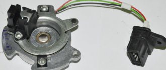
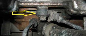
Location of the electrical connector (1) supplying voltage to the fuel injector and connector (2) on the fuel injector
PERFORMANCE ORDER 1. Disconnect the electrical connector from the fuel injector of the first cylinder, see fig. Location of the electrical connector (1) supplying voltage to the fuel injector and connector (2) on the fuel injector. 2. Connect the control LED to the connector contacts (1) (see Fig. Location of the electrical connector (1) supplying voltage to the fuel injector and connector (2) on the fuel injector). When the engine cranks with the starter, the LED should flash. 3. Check the voltage supply to the remaining fuel injectors in the same way.
The LED does not blink on any of the cylinders
Location of contacts on the electrical connector supplying voltage to the fuel injector
PERFORMANCE ORDER 1. Connect the control LED to contact No. 1 of the electrical connector to supply voltage to the fuel injector and vehicle ground, see fig. Location of contacts on the electrical connector supplying voltage to the fuel injector. 2. Connect pin No. 2 of the electrical connector to vehicle ground. 3. Turn the engine crankshaft with the starter. In this case, the LED should blink. Otherwise, check the entire electrical circuit supplying the fuel injectors.
LED does not flash on only one or more cylinders
PERFORMANCE ORDER 1. Check the condition of the electrical circuit powering the fuel injectors and determine and eliminate the location of the electrical circuit break or short circuit to ground. 2. Check the operation of the engine control unit.
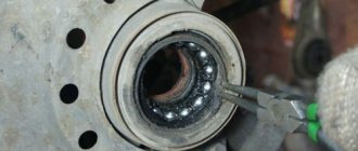
Connection points for an ohmmeter to check the resistance of fuel injectors
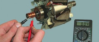
PERFORMANCE ORDER Sequentially disconnect the electrical connectors from the fuel injectors and, using an ohmmeter, check the resistance of the fuel injectors, which should be in the range from 12 to 17 Ohms, see fig. Connection points for an ohmmeter to check the resistance of fuel injectors.
Warning When the engine is warmed up to normal operating temperature, the resistance of the fuel injectors increases by 4–6 ohms.
If the fuel injector resistance is not as specified, replace the fuel injector.
The fuel injector is an integral part of the vehicle's injection system. Naturally, the quality of the car as a whole depends on the proper operation of the injectors. Although engine compartment problems should be handled by a trained professional, you can determine the source of the problem yourself.
Installation locations
On cars, the injection system is equipped with a separate line for draining excess gasoline, which goes from the fuel rail to the gas tank (fuel recirculation). In such injectors, the regulator is installed directly on the fuel rail (or connected to it), so the unit quickly “reacts” to changes in engine operating conditions and adjusts the pressure in the rail. In this design of the power system, a mechanical type RTD is used.
There is another version of the injector - without gasoline recirculation. In this system there is no “return” at all, and regulation is carried out at the output of their fuel pump. A feature of such a system is the location of the regulator - in the tank or near it. An RTD is already used here, the operation of which is controlled by the ECU - the control unit, through a sensor installed in the ramp, monitors the necessary parameters and corrects them by sending signals to the regulator.
Power systems with electronic regulators are used less frequently than mechanical ones due to their complex design and, accordingly, lower reliability.
Possible malfunctions: causes, manifestations, consequences
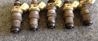
Naturally, fuel injectors require periodic inspection and cleaning, and, if necessary, even replacement. Problems can be identified by a number of symptoms, including:
- The appearance of uncharacteristic failures when starting the power unit and when it is idling;
- Increased consumption;
- Uncharacteristic exhaust color.
After the first manifestations of the problem, we can talk about the presence of sulfur deposits on the system elements, corrosion, wear of filters and some working parts. As a result of the influence of each process, the fuel mixture supply system becomes clogged, and, consequently, a loss of power and high consumption.
The instruction manual states that the injectors must be cleaned every 20–30 thousand kilometers. In practice, this interval is reduced to 10–15 thousand km.
Checking power supply to injectors
If the driver notes that all injectors are working properly, but when the ignition is turned on, the injector refuses to work, then it makes sense to check the pulse supply to the injectors.
To properly check, you need to disconnect the block from the injector and prepare two wires for connecting them to the battery. The second contacts are connected to the injectors.
Then, after preparation is completed, the ignition is turned on and fuel leakage analysis is carried out. The main task is to record the presence or absence of a leak. As a result, if fuel leaks, then we can talk about problems in the operation of the entire electrical circuit. If no leakage is observed, then the system is working properly.
Measuring resistance using a multimeter
One of the main methods used to determine fuel injector failures is to measure resistance using a multimeter. Before starting work, it is important to determine the factory impedance of the TF.
When diagnosing, the ignition must be turned off and the negative terminal from the battery disconnected. The corresponding electrical connector on the injector is disconnected. This can be done using a screwdriver with a fairly thin end - the clamp on the block snaps off.
The multimeter must be switched to ohmmeter mode and the corresponding contacts must be connected. The results obtained between the center and outer contacts should fall in the range of 11-17 ohms for high impedance injectors or in the range of 2-5 ohms for low impedance injectors.
The presence of any deviations from the norm provides grounds for a more detailed diagnosis. In some cases, the fuel injector is replaced with a known good one in order to evaluate the operation of the power unit.
Video text
Good afternoon, colleagues! We bring to your attention the final part of the series dedicated to the express diagnostics of Common Rail systems. In this video we will look at a unique diagnostic technique for hanging diesel injectors with the GrunBaum CR150/CR350/CR550 kit.
Find out all GrunBaum technologies: https://goo.gl/EK43PF
Watch all the videos in this series at the link: https://www.youtube.com/playlist?list.
Subscribe to our groups on social networks:
Source m.youtube.com
The quality of fuels and lubricants is a topic of eternal debate. Some pour the branded drink and rejoice that the car suddenly goes faster. Others suddenly pour the same into a one-year-old car and, not feeling the effect, continue to complain about the gas station chain. Meanwhile, it is enough to refuel with anything once and the injector will be in trouble.
Checking the injector balance
To balance the fuel pump, you must first turn off the fuel pump and start the car. After a few seconds of operation, the engine should stall - this is necessary to eliminate excess pressure of the mixture. Then the pressure gauge is connected, and only after that the fuel pump returns to its place. Next, a computer with the necessary software is connected and diagnostics are carried out.
Subsequent actions are performed exclusively using specialized programs. You may notice that the fuel pump will gradually turn on and off, as will the injectors. In general, the following algorithm can be distinguished:
- Turning on the ignition;
- Pressure gauge readings are in the range of 2.8–3 atm;
- The fuel pump turns off;
- Pressure drop to 2.5–2.8 atm;
- Checking one TF;
- Analysis of pressure gauge data – significant dynamics should not be observed;
- The pressure is restored to its original value by turning on the fuel pump;
- The procedure is repeated one by one with all nozzles.
When working correctly, each element will give approximately the same performance. If the reset is different in a certain place, then we can talk about a malfunction of the injector or its further diagnostics. After completing the manipulations, the pressure gauge must be turned off only after first releasing the pressure in the system.
VAZ-2110 diagram for an injector with 8 valves - applicability for repairs
Now more and more motorists are trying to replace the carburetor on their VAZ-2110 with an injector, which has a number of significant advantages. It allows the valves in the engine to work much more efficiently, reducing the load on the engine and the average fuel consumption in the car. At the same time, it is simply impossible to install an injector without a diagram, even if you are a professional car service worker.
Contents: 1 Why is the VAZ-2110 electrical circuit needed? 2 The main elements of an injector with 8 and 16 valves and their functions 3 How to adjust the fuel supply process using an electrical circuit? 4 How does the controller monitor the operation of the injector? 5 How does a malfunction of the electronic control unit affect the operation of the injector?
Why is the VAZ-2110 electrical circuit needed?
When replacing or repairing an injector with 8 valves, the electrical diagram serves as a kind of guide, with the help of which you can understand all the nuances in the process of connecting specific wiring parts. In addition, the VAZ-2110 electrical diagram when using an injector with 8 valves allows you to understand the functioning of all electrical wiring devices.
In the diagram, the injector valves are evenly spaced, while the system itself is presented in the form of two combined components:
- Fuel distributor;
- Electrical equipment for the ignition control system.
Also, the diagram with 8 and 16 valves indicates the location of the electronic unit, with the help of which the operation of the above two systems is coordinated. Backup equipment, in turn, protects electrical wiring from overloads and increases the operating efficiency of the entire injection system.
Advice: if you are going to repair the injector, be sure to look at the wiring diagram for the VAZ-2106. This will give you the opportunity to replace any faulty parts without affecting the overall functioning of the vehicle's wiring.
The elements indicated by numbers in the diagram are shown below:
| 1 - block headlight | 35 — instrument lighting switch |
| 2 — front brake pad wear sensors | 36 - ignition switch |
| 3 - reverse light switch | 37 — mounting block |
| 4 — electric motor of the engine cooling system fan | 38 - recirculation valve switch |
| 5 - sound signal | 39 - heater controller |
| 6 — gear motor for locking the lock of the right front door | 40 - hazard switch |
| 7 - relay for turning on electric windows | 41 — lamp for illuminating the heater control levers |
| 8 - 8 A fuse | 42 — glove box lighting lamp |
| 9 - starter | 43 - glove compartment lamp switch |
| 10 - battery | 44 - cigarette lighter |
| 11 - generator | 45 — display unit of the on-board control system |
| 12 - windshield washer motor | 46 — ashtray lighting lamp |
| 13 — washer fluid level sensor | 47 - brake light switch |
| 14 — gear motor for locking the left front door lock | 48 — gear motor for locking the left rear door lock |
| 15 — left front door power window switch | 49 - left rear door power window switch |
| 16 - coolant level sensor | 50 — electric window motor reducer of the left rear door |
| 17 - windshield wiper gearmotor | 51 - socket for a portable lamp |
| 18 — recirculation valve | 52 - hours |
| 19 — micromotor gearbox for heater damper drive | 53 — electric window motor reducer of the right rear door |
| 20 — heater electric motor | 54 - right rear door power window switch |
| 21 — trunk lock switch | 55 — gear motor for locking the right rear door |
| 22 — right front door power window switch | 56 - side turn signal |
| 23 — electric window motor reducer of the right front door | 57 - parking brake warning lamp switch |
| 24 - control unit for door lock system | 58 - driver's seat belt sensor |
| 25 - additional resistor of the heater electric motor | 59 — directional lamp |
| 26 — brake fluid level sensor | 60 — interior lamp |
| 27 — electric window motor reducer of the left front door | 61 — cabin air temperature sensor |
| 28 — external lighting switch | 62 — switch in the front door pillar |
| 29 - instrument cluster | 63 — switch in the rear door pillar |
| 30 - rear fog light switch | 64 — external rear light |
| 31 - fog light indicator lamp | 65 — internal rear light |
| 32 - indicator lamp for heated rear window | 66 — license plate lights |
| 33 - rear window heating switch | 67 — trunk light |
| 34 — steering column switch |
The diagram of electrical wires and fuses gives an understanding of the entire operation of the injection system, and also shows the specific position of each of the elements. It contains the following elements:
- Central nozzle. Acts as a distributor of fuel supply to the system. There is also a special type of fuel regulator that works as a sensor and ensures that the fuel supply does not go beyond the normal limits.
- Diaphragm regulator. Monitors fuel pressure in the ignition system and removes excess fuel back into the tank body.
Advice: make sure that the pressure in the fuel supply system does not exceed 300 MPa. Otherwise, you will see the corresponding icon on the instrument panel and you will most likely have to replace the coolant on the VAZ-2110.
- Bypass valve design. It regulates the position of the cross diaphragm, which is subject to constant pressure from three sides: on one side, the pressure of the fuel itself, on the other side, the tangential load from the intake air volumes, and on the 3rd side, the tension from the spring attached to the valve.
How to adjust the fuel supply process using an electrical circuit?
According to the scheme described above, fuel regulation in a car is carried out. Moreover, it depends not only on the load of the valves in the engine, but also on the corresponding position relative to the throttle valve. With the help of a diagram of electrical wiring and valves, it is possible to understand which of the relays or fuses is malfunctioning and replace it in time. In this case, one of the main roles when supplying fuel is played by electrical equipment (controllers) that regulates the operation of the injector.
How does the controller monitor the operation of the injector?
When determining the specific position and opening time of the injector design, the specific volume of fuel entering the valves of the VAZ-2110 cylinder is determined. At the same time, thanks to special sensors installed on the motor, the on-board computer records specific values and transmits them to the controller.
Subsequently, the controller, based on the information coming from the on-board computer, makes a decision on the position and duration of opening of the injector damper. If the controller malfunctions, the injectors will not be adjusted correctly, and the engine may stall while driving.
Tip: when starting the engine, the injector controller operates in asynchronous mode until the engine reaches a certain number of revolutions. That is why, after replacing the silent blocks of the front control arms on a VAZ-2110, you should warm up the car for 10-15 minutes.
How to clean injectors without removing them from the engine?
Usually, the most common problem with TFs is their improper or untimely cleaning, as a result of which they become clogged. There are three types of cleaning:
To clean the injectors without removing them, it is usually enough to select and pour a chemical composition into the fuel tank that can normalize operation. From time to time it is recommended to accelerate the engine to high speeds and speeds of 110–140 km/h on flat sections of the road. When covering a distance of 10–25 km in this mode, the system undergoes “self-cleaning” under load.
However, such methods are effective only for minor stains. Large lesions must be removed using ultrasound or high pressure. And in order to prevent this, it is necessary to wash the fuel filter every 40–50 thousand kilometers.
You can visually familiarize yourself with the technique of checking injectors with your own hands in the video:
Simple instructions with photos and video examples on how to independently check injectors on VAZ 2113, 2114, 2115 cars.
To carry out work on checking the injectors you will need: A wire 2 meters long, electrical tape, a multimeter.
- Remove the decorative trim from the 1.6 engine.
Disconnect the injector wiring harness connectors.- Turn on the ignition and use a voltmeter to measure the voltage at terminal E of the wiring harness block. The voltage must be at least 12V.
- After taking measurements, turn off the ignition. If, as a result of measurements, it turns out that there is no voltage on the block or it is less than 12V, then you need to check the battery charge, the power circuit and the serviceability of the computer.
- We check the electrical resistance of the injectors, for which we use an ohmmeter to alternately measure the resistance between terminal E and the other four terminals of the block (2). The block terminal marked with the letter B corresponds to the injector of the first cylinder, and terminals C, G and F correspond, respectively, to the injectors of the second, third and fourth cylinders. For serviceable injectors, the resistance should be 13 ohms.
- When performing the following operation, do not apply voltage more than 12 V to the terminals of the block, and after performing the test, do not leave the terminals under voltage, as this may lead to burnout of the injector windings.
- Using two wires directly from the battery, we briefly apply 12 V voltage to the terminals of the block (2) - connect terminal E to the positive terminal of the battery, and terminals B, C, G and F in series with the negative terminal of the battery. For a working injector, a characteristic click should be heard when the valve opens.
- We replace faulty injectors.