During its operation, the engine heats up to a very high temperature threshold. This circumstance is very fraught with problems for all surrounding elements. This is also dangerous for those people who are in the cabin. That is why a special complex was developed in order to “pacify” elements ready to boil.
This allows you not to worry that something will “boil” during operation. The latest VAZ 21214 models are equipped with a four-cylinder 8-valve gasoline engine system. It was here that the fuel injection system found its application. This is reflected in this set.
Engine cooling system
The cooling system is liquid, closed type, with forced circulation.
The tightness of the system is ensured by valves in the expansion tank plug. The inlet valve is normally open (the gap between it and the rubber gasket is 0.5–1.1 mm) - in this case, the system communicates with the expansion tank. When the engine heats up, the liquid expands and is forced into the tank; when it cools, it returns back. The inlet valve closes when there is a sharp increase in pressure in the system (boiling liquid), while the outlet valve is also closed. It opens when the pressure in the system reaches approximately 0.5 kgf/cm2, which increases the boiling point of the liquid and reduces its losses. The thermal operating conditions of the engine are maintained by a thermostat and a radiator fan. On a carburetor engine, the fan is mechanically driven and mounted on the coolant pump pulley. On an engine equipped with an injection system, two electric fans are installed in front of the radiator and are activated by command from the electronic engine control unit. Carburetor engine cooling system
Injection engine cooling system
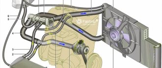
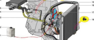
1 – expansion tank; 2 – expansion tank plug; 3 – pipe for draining fluid from the heater radiator; 4 – hose for draining fluid from the heater radiator; 5 – heater tap; 6 – heater radiator; 7 – hose for supplying fluid to the heater radiator; 8 – hose for supplying fluid to the carburetor heating block; 9 – hose for draining fluid from the carburetor heating unit; 10 – thermal vacuum switch of the recirculation valve; 11 – thermostat bypass hose; 12 – coolant pump cover; 13 – fan impeller; 14 – coolant temperature sensor for the instrument cluster; 15 – radiator supply hose;
16 – radiator; 17 – radiator cap; 18 – radiator drain plug; 19 – fan casing; 20 – radiator outlet hose; 21 – coolant pump drive belt; 22 – coolant pump housing; 23 – hose for supplying coolant to the pump; 24 – thermostat; 25 – coolant supply hose to the throttle body; 26 – coolant drain hose from the throttle body; 27 – coolant temperature sensor for the injection system; 28 – electric fan impeller; 29 – electric motor; 30 – electric fan casing.
The coolant pump is a vane, centrifugal type, driven from the crankshaft pulley by a V-belt. The pump housing is aluminum. The roller rotates in a double-row bearing with a lifetime supply of lubricant. The outer ring of the bearing is locked with a screw. A pulley hub is pressed onto the front end of the roller, and a plastic impeller is pressed onto the rear end. For the correct position of the pump pulley groove, the distance from the mating surface of the pump cover to the outer end of the hub must be 84.4 ± 0.1 mm. When installing the cover with the gasket, check the gap of 0.9–1.3 mm between the impeller blades and the pump housing. To do this, you can use plasticine rollers: they are placed on equidistant impeller blades, a cover is installed, the nuts securing it are tightened, then the cover is removed and the remaining thickness of the plasticine is measured - it is equal to the gap.
Axial and radial play in the pump bearing that can be felt by hand is not allowed. If the bearing or self-pressing seal of the pump fails, it is recommended to replace the pump cover complete with the roller and impeller.
The redistribution of liquid flows is controlled by a thermostat with a solid heat-sensitive element. On a cold engine, the thermostat valve closes the pipe leading to the radiator, and the liquid circulates only in a small circle (through the thermostat bypass pipe), bypassing the radiator. The small circle includes the heater radiator, intake manifold, carburetor heating unit (on engine 21213) or throttle assembly (on engine 21214). At a temperature of 78–85°C, the valve begins to move, opening the main pipe; in this case, part of the liquid circulates in a large circle through the radiator. At a temperature of about 90°C, the main valve opens completely, and the bypass valve closes, and all the liquid circulates through the engine radiator. The main valve stroke must be at least 6.0 mm.
You can evaluate the serviceability of the thermostat by heating the lower radiator pipe: it should be cold until the liquid temperature (according to the indicator) reaches 80–85°C, and hot when it rises to 85–90°C. The thermostat is beyond repair. In case of malfunction, loss of tightness, or deformation of the pipes, it is replaced.
The radiator consists of two vertical plastic tanks (the left one has a baffle) and two horizontal rows of round aluminum tubes with pressed-on cooling plates. To increase cooling efficiency, the plates are stamped with a notch. The tubes are connected to the tanks through a rubber gasket. The liquid is supplied through the upper pipe and discharged through the lower. There is a coolant drain plug at the bottom of the left reservoir.
For better radiator airflow, casings are designed to direct air flow from the fan(s).
On the 21213 engine, the main fan shroud consists of two halves (lower and upper), the lower half has a rubber seal on the radiator side. An additional guide casing is installed in front of the radiator. On the 21214 engine, electric fans rotate in a casing in front of the radiator.
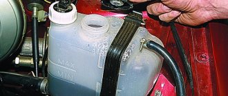
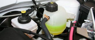
The expansion tank is made of translucent polyethylene, which allows you to visually monitor the fluid level (3–5 cm above the “MIN” mark on a cold engine).
To monitor the coolant temperature, a sensor is screwed into the engine cylinder head and is connected to a temperature gauge on the dashboard. An additional temperature sensor is installed in the exhaust pipe of the 21214 engine, which provides information to the electronic engine control unit (see here).
The heating system is described here.
Video
How does cooling work on the VAZ 2121 Niva?
The lifespan of a Niva SUV engine largely depends on how efficiently the VAZ-2121 cooling works. After all, overheating is the first enemy of the power unit, leading to expensive repairs.
This is why the serviceability of the components and elements of the cooling circuit is so important. In order to be able to service them and identify malfunctions, you need to understand what the circuit consists of and how the Niva’s cooling functions.
Vehicle cooling network design
The cooling system of the VAZ Niva is quite effective and has undergone virtually no changes since its creation. It includes the following units and elements:
Temperature control in the Niva engine cooling network is carried out in different ways. In the carburetor model VAZ-21213, a sensor is built into the cylinder head, connected to the temperature indicator on the dashboard. On the VAZ-21214 model, where the fuel is supplied by an injector, there is a second sensor mounted in the pipe on the cylinder head. It is connected to a controller that prepares the fuel mixture depending on the heating of the power unit and turns on the fans.
There are 2 more differences in the cooling design of engines with a carburetor and an injector:
- on cars with direct fuel injection, 2 electric fans are installed on the radiator instead of 1 mechanical;
- The heating pipes for the lower part of the carburetor in model 21214 provide heating for the throttle body.
In VAZ-2131 Chevrolet Niva cars, the cooling system is generally similar to a regular Niva with an injector. The VAZ-2131 heater radiator is not equipped with a tap, which is why antifreeze flows through it all year round.
Operating principle
The Niva's cooling circuit operates under pressure, since in normal mode it does not communicate with the atmosphere. The coolant is antifreeze with a freezing point of -40 °C. It is a solution of water with ethylene glycol, the amount to fill the system is 10.7 liters. It also boils at an elevated temperature, +110 °C.
The key element in the operation of the system is the thermostatic valve, which distributes fluid flows depending on the heating of the engine. Inside the thermostat there is a damper controlled by a temperature-sensitive element. When heated, it moves the damper, opening another path for the flow. In general, the scheme works according to the following algorithm:
In the summer and transition period in VAZ-21213 and 21214 cars, the passage of coolant through the heater radiator is limited by a tap. There is no such tap on the Chevrolet Niva; the heating is turned off by redirecting the air flow past the heat exchanger.
Main fuse box
Scheme
p, blockquote 12,0,0,0,0 —>
p, blockquote 13,0,0,0,0 —>
Purpose
p, blockquote 14,0,0,0,0 —>
| 1 | 16A Heater fan electric motor Relay (winding) for headlight wipers and electric motors for headlight wipers in all wipe positions except the initial Relay (winding) for turning on the rear window heating Electric motors for the rear window cleaner and washer Electric motor for the windshield washer |
| 1* | 16A Lamps Horns Socket Lighter Brake light |
| 2 | 8A Relay and electric motor of the windshield wiper Turn signal lamps and relay-interrupter for direction indicators and hazard warning lights (in turn signal mode) Turn signal indicator lamp Tail lights (reversing light lamps) Generator excitation winding (when starting the engine) Differential lock activation indicator lamp in the transfer case Indicator lamp for turning on the parking brake Indicator lamp for the emergency condition of the service brake system Indicator lamp for insufficient oil pressure Fluid temperature indicator in the engine cooling system Fuel level indicator with a warning lamp for fuel reserve Indicator lamp for battery charge Indicator lamp for closing the carburetor air damper Tachometer Electric heater motor Relay headlight cleaners and washer (with the headlight cleaner and washer switch button not pressed) Headlight wiper electric motors in all brush positions except the initial one* |
| 3 | 8A Left headlight (high beam lamp) Indicator lamp for turning on the high beam headlights |
| 4 | 8A Right headlight (high beam lamp) |
| 5 | 8A Left headlight (low beam) |
| 6 | 8A Right headlight (low beam) |
| 7 | 8A Left front light (side light) Right rear light (side light) License plate lights Indicator lamp for turning on side lights |
| 8 | 8A Right front light (side light) Left rear light (side light) Instrument lighting lamp Heater control lever backlighting lamp Cigarette lighter lighting lamp Illumination lamps for switches and switches |
| 9 | 16A Direction indicators and relay-breaker for direction indicators and hazard warning lights Rear window heating element and relay (contacts) for its activation |
| 9* | 8A Warning lamp and oil pressure gauge Coolant temperature gauge Fuel level gauge with reserve warning lamp Parking brake warning lamp Brake fluid level warning lamp Turn indicators and corresponding warning lamp Carburetor choke control warning lamp Battery charge warning lamp Carburetor shut-off valve Tachometer Rear lights (reverse light) Differential lock warning lamp Turn signal relay interrupter Heated rear window (control circuit) |
| 10 | 16A Sound signal Cartridge for connecting a portable lamp Interior lamps Tail lights (brake lamps) |
| 10* | 8A Voltage regulator Generator excitation winding |
| 11 | 8A Turn signal lamps and relay-breaker for turn signals and hazard warning lights (in hazard warning mode) Rear fog lamp |
| 12 | 8A Daytime running light relay, daytime running light lamps |
| 12* | 8A Headlight cleaner and washer relay (with the headlight cleaner and washer switch button pressed) Headlight washer electric motor Headlight cleaner electric motors at the moment of start-up and when the brushes pass the initial position |
| 13 | 8A Rear lights (fog light lamps) Electric motors for headlight cleaners at the time of start-up and when the brushes pass the initial position Relays (contacts) for headlight cleaners Electric motor for headlight washers |
| 14 | 16A Cigarette lighter |
| 15 | 16A Backup Heated rear window (power circuit) |
| 16* | 8A Hazard warning switch and direction indicators in hazard warning mode Rear window wiper and washer |
Fuse number 14 or number 1 at 16A is responsible for the operation of the cigarette lighter, depending on the year of manufacture.
Possible faults
To avoid problems with engine overheating, it is necessary to monitor and maintain the Niva’s cooling system.
You should check the antifreeze level in the expansion tank more often. Due to the reliability of cooling, there are not many malfunctions in it:
- When the car heats up to maximum in any weather, and the main radiator pipes are cold, the thermostat has broken. The element is not repaired, only changed.
- Electric fans turn on at random, including when the engine is cold, but if they overheat, they may not start. This means that the sensor transmitting temperature data to the controller has failed and must be replaced.
- When the indicator on the panel gives inaccurate data or does not show the temperature, you need to change the second sensor located in the cylinder head.
- The fluid level in the tank is constantly decreasing. It is necessary to look for and eliminate leaks in the pipes or in one of the radiators.
It is important to periodically check for play in the water pump shaft. Its appearance indicates wear of the bearing; it is necessary to change the pump as soon as possible.
Main element device
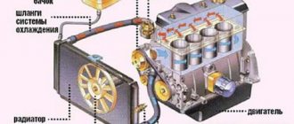
As for the cooling radiator, it is impossible to imagine the operation of the engine as a whole without it. It is represented by these components:
- upper and lower tanks;
- core;
- fastening parts.
Its main purpose is to cool the mixture coming from the water jacket to the required temperature standard. Good thermal conductivity is facilitated by the fact that it is usually made of brass. The core contains transverse plates. Once here, the reagent is divided into many streams - this allows you to get a more effective result.
The principle of operation goes like this:
- The pump constantly “moves” liquid into the VAZ 21214.
- The system operates in such a way that water circulates in a circle, washing the heated walls of the blocks and cylinder.
- In this case, engine overheating can be avoided, and heat will be guaranteed to be removed from important parts.
- Then the mixture goes through the radiator, and after that it is released into the environment.
- Thus, the cyclicity is completed - now the cooled liquid will have to repeat it again for the VAZ 21214.
Engine cooling system for VAZ NIVA VAZ21213 and VAZ-21214
1. Coolant temperature sensor for the fuel injection system. 2. Radiator supply hose. 3. Tank cap. 4. Expansion tank. 5. Radiator cap. 6. Hose from the radiator to the expansion tank. 7. Cooling jacket. 8. Filler neck. 9. Plug inlet valve. 10. Exhaust (steam) valve of the plug. 11. Left radiator tank. 12. Radiator core. 13. Right radiator tank. 14. Fan impeller. 15. Turbulizer. 16. Rubber radiator support. 17. Fan shroud. 18. Fan belt. 19. Radiator outlet hose. 20. Coolant pump. 21. Coolant supply hose to the pump. 22. Thermostat. 23. Thermostat bypass hose. 24. Fluid drain pipe from the heater radiator. 25. Fluid drain hose from the carburetor heating unit. 26. Fluid supply hose to the carburetor heating unit. 27. Fluid drainage hose from the heater radiator. 28. Fluid supply hose to the heater radiator. 29. Rubber insert. 30. Inlet pipe (from the radiator). 31. Main valve. 32. Thermostat housing. 33. Bypass valve. 34. Overflow hose connection. 35. Coolant supply pipe to the pump. 36. Thermostat cover. 37. Piston. 38. Pump cover. 39. Thrust seal ring of the oil seal. 40. Oil seal. 41. Pump roller bearing. 42. Fan pulley hub. 43. Locking screw. 44. Pump roller. 45. Pump housing. 46. Pump impeller. 47. Intake pipe. I. Thermostat operation diagram. A. Liquid temperature is less than 80oC. B. Liquid temperature is from 80 to 94oC. C. Liquid temperature is more than 94oC.
The engine cooling system is liquid, closed, with forced circulation of coolant. The system is filled with Tosol D-40 coolant and an aqueous solution of Tosol-A antifreeze (concentrated ethylene glycol with anti-corrosion and anti-foaming additives with a density of 1.078-1.085 g/cm2).
The cooling system is filled with 10.7 liters, including the interior heating system. The fluid level in the expansion tank should be 3-4 cm above the “MIN” mark, checked on a cold engine (at 15-20°C).
To monitor the coolant temperature, there is a sensor installed in the cylinder head and a pointer on the instrument panel.
The cooling system includes: coolant pump 20, cooling jackets for the block and cylinder head, thermostat 22, fan, radiator, expansion tank 4, pipelines and hoses. When the engine is running, liquid heated in the cooling jackets flows through the outlet pipe through hoses 2 and 23 into the radiator or thermostat, depending on the position of the thermostat valves. Next, the cooled liquid is sucked in by pump 20 and supplied again to the cooling jackets. The coolant pump is a centrifugal type, driven from the crankshaft pulley by a V-belt that drives the generator.
The pump housing 45 and cover 38 are cast from aluminum alloy. In the cover, in bearing 41, which is locked with a screw 43, a roller 44 is installed. Bearing 41 is double-row, non-separable, without an inner race. The bearing is filled with Litol-24 grease during assembly and is not subsequently lubricated.
A cast iron impeller 46 is pressed onto the roller on one side, and the hub 42 of the pump drive pulley is pressed onto the other side. The end of the impeller in contact with the sealing ring is hardened with high frequency currents to a depth of 3 mm. The sealing ring is pressed against the impeller by the oil seal spring through a rubber collar. Oil seal 40 is non-separable and consists of an outer brass ring, a rubber cuff and a spring. The oil seal is pressed into the pump cover 38. The pump is driven by a V-belt 18.
The fan is a six-blade impeller 14 made of plastic, which is bolted to the hub 42 of the pump drive pulley. The fan blades have a variable radius installation angle and, to reduce noise, a variable pitch along the hub. For better operating efficiency, the fan is located in a casing 17, which is bolted to the radiator brackets.
Radiator and expansion tank. The radiator is collapsible, with plastic tanks 11 and 13, with two rows of aluminum horizontal tubes and aluminum cooling plates. The radiator core 12 is sealed with the tanks using rubber gaskets. For better cooling efficiency of the liquid, turbulators 15 are installed in the tubes. The radiator is mounted on rubber supports 16 and bolted to the front of the body. The filler neck of the radiator is closed with a plug 5 and connected by a hose to a translucent plastic expansion tank 4. The radiator plug has inlet 9 and outlet 10 (steam) valves, through which the radiator is connected to the expansion tank. The inlet valve 9 is not pressed against the gasket (the gap is 0.5-1.1 mm) and allows the inlet and outlet of coolant into the expansion tank when the engine is heating and cooling.
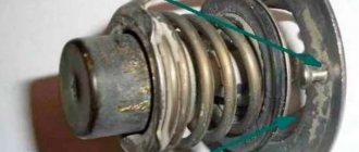
When the liquid boils or a sharp increase in temperature due to low throughput, the inlet valve does not have time to release liquid into the expansion tank and closes, disconnecting the cooling system from the expansion tank. When the pressure increases when heated to 50 kPa, the outlet valve 10 opens, and part of the coolant is transferred into the expansion tank. Thermostat and cooling system operation. The cooling system thermostat accelerates engine warm-up and maintains the required thermal operating conditions of the engine. At optimal thermal conditions, the coolant temperature should be in the range of 85-95°C. The temperature values maintained by the thermostat are indicated on its bottom.
Thermostat 22 consists of a body and a cover, which are rolled together with the seat of the main valve 31. The thermostat has three pipes: an inlet pipe for inlet of coolant from the radiator, a pipe bypass hose 23 for bypassing liquid from the cylinder head to the thermostat, and a pipe for supplying coolant to the pump. 20.
The main valve 31 is installed on the thermoelement glass, in which a rubber insert 29 is rolled. The rubber insert contains a polished steel piston mounted on a stationary holder. Between the walls and the rubber insert there is a heat-sensitive solid filler. The main valve 31 is pressed against the seat by a spring. Two posts are attached to the valve, on which a bypass valve 33 is installed, pressed by a spring.
The thermostat, depending on the temperature of the coolant, automatically turns on or off the radiator of the cooling system and bypasses the liquid through the radiator or bypassing it
On a cold engine, when the coolant temperature is below 80°C, the main valve is closed and the bypass valve is open. In this case, the liquid circulates through the hose 23 through the bypass valve 33 into the pump 20, bypassing the radiator (in a small circle). This ensures quick warm-up of the engine.
If the liquid temperature rises above 94 ° C, the solid filler of the thermostat expands, compresses the rubber insert 29 and pushes out the piston, moving the main valve 31 until it is completely open. The bypass valve 33 closes completely. In this case, the liquid circulates in a large circle: from the cooling jackets through hose 2 to the radiator and then through hose 19 through the main thermostat valve it enters pump 20, which is again sent to the engine cooling jackets.
Within temperatures of 80-94°C, the thermostat valves are in intermediate positions, and the coolant circulates in both small and large circles. The opening value of the main valve ensures gradual mixing of liquid cooled in the radiator, thereby achieving the best thermal operating conditions of the engine.
Silicone pipes from CS20
Dear reader, welcome to another entry about forced repairs, of which there have been the majority lately. We will talk about replacing the cooling and heater pipes. There will be a lot of text, so sit down comfortably, and I’ll probably start.
The thermometer showed the first minus, everyone rushed headlong to the tire repair shop. I have an ordinary working day - I need to go on business, but first take my wife to work. We go out into the yard, out of habit, I inspect the car for damage and flat tires, what I see:
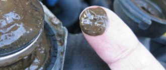
Well, that's mine! Twenty-five again. I determined that it was antifreeze and that there was a small leak - I warmed up and flew to work. At lunchtime I started to carefully study what the problem was and where it came from. It turns out - from everywhere! I was stunned, all the joints were wet, naturally the idea came to try to tighten the clamps. But due to the fact that they are made of feces, one after another they began to turn, hmm.
Total purchased: a complete set of CS20 pipes (auto catalog number: 2121-1303080 / 2123-1014056 / 21214-8101200 / 21214-8101204 / 21213-1303010 / 21213-1303025 / 21213-13030 90 / 21213-1303092), set of power clamps 23 -25mm. 6 pcs., 40-43 8 pcs., (exactly for this model of pipes, recommended by the manager), new thermostat “Belmag VM7748” 85 g. (I didn’t buy from them), silicone high-voltage wires #CS20 (article: 21214-3707080-10) and a couple of rubber bands for the stove tap and oil filler cap (naturally silicone) and a 4L canister of my favorite TCL Long life Green (article: LLC01243).
In terms of quality: the pipes look decent (use will show), but when purchasing, pay attention to the inside - there is strange sludge and silicone deposits, and also some kind of oxidized power clamps (I think in a couple of thousand they will look extremely unpresentable).
When I had everything I needed in my hands, I rushed to the garage, turning on the heater there in advance)). I drain the antifreeze (by the way, for those who in previous posts claimed that it makes no difference what to pour - Sintec or TCL, they say everything is from the same barrel):
Then I remove the old pipes and thermostat:
And I assembled them on new ones, first I tried them on without clamps.
Well, of course, “bolt on” didn’t work, the thermostat is under tension and too low. I trimmed it by 20 mm. from the one between the thermostat and the head, between the thermostat and the radiator, the VGK pipe and the stove.
Clamps 40-43 do not tighten properly (with the exception of the fitting from the block), that is, they are tightened completely but the pipe is not properly compressed. I was worried that it would leak under pressure. As for the 23-25mm clamps, they don’t fit the stove pipes at all, so I played it safe and bought spring ones just in case. I assembled the stoves specifically for them:
I fill the antifreeze back in, remove the air and install new wires:
Wires: they seem to be of high quality, but... The cylinder numbers are not marked and two are longer than the standard ones, which led to hiding the remains down so that the spare tire would not fall on them. Everything seemed to be victory! But after the test drive, antifreeze poured out of the connections to the heater, on the thermostat, and at the top and bottom of the radiator. There was even a leak from the expansion tank pipe (((. But there’s no way to tighten it up.
Disappointed, I went home. The next day I drove to the store for new strength. clamps: I took the main ones 36-39mm (I left 40-43 on the fitting from the block, it fit well!), for the stove and expansion tank 20-22mm (the clamp of the fitting of the tank itself is 23-25).
Source
How to change antifreeze on a VAZ 21214 Niva
The Niva SUV, in all modifications, is very popular in Russian spaces. This is due to good maintainability, low price and excellent maneuverability. To ensure reliable operation, you should undergo all maintenance on time, in particular, replace the coolant.
The liquid system with forced circulation of the VAZ 21214 car is designed for effective heat removal. It fully copes with its task, you just need to keep it in good condition.
Replacing antifreeze VAZ 21214
Replacing the coolant is a regulated maintenance procedure, which is prescribed in the operating instructions. There is nothing complicated about it if you clearly and carefully follow the described action plan.
Suitable for Niva cars:
Coolant drain
Before starting the draining procedure, you should prepare tools, containers for used antifreeze, as well as new liquids for subsequent refilling. If protection is installed under the engine, it can also be removed for convenience.
Next, we perform the procedure for draining the liquid from the VAZ 21214 (Niva):
- turn the temperature regulator in the cabin to the maximum position to the right (Fig. 1);
Flushing the cooling system
If there are deposits in the drained liquid or there is a transition from antifreeze to antifreeze, the system should be flushed. To do this you need to do the following:
- Flush the system with plain water through the expansion tank of the VAZ 21214. The plugs must be open;
- tighten the drain plug and bolt;
- fill the system with a flushing agent (you can use Liqui Moly Kuhlerreiniger or Lavr cooling system flush) with distilled water (6-7 liters);
- start the engine. Warm up to 90 degrees;
- leave it idling for 5-10 minutes, depending on the contamination of the system;
- muffle it. Allow the engine to cool to approximately 60 degrees;
- drain the flush using the same steps as removing the old fluid;
- tighten both plugs;
- fill with distilled water to rinse the cooling system;
- start the car and warm up to 90 degrees;
- turn off and let cool to 60 degrees, drain;
- repeat steps 8, 9, 10 and 11 if necessary.
Filling antifreeze into Niva 21214, 21213 without air locks
To fill new fluid into the cooling system, you can use the instructions described in the book on car repair and operation. But when doing this, motorists very often end up with air jams.
So, let's start filling it correctly:
- before filling, unscrew the hoses supplying antifreeze to the throttle valve heating unit and lift them slightly up (Fig. 1);
The filling of the liquid is completed, all that remains is to wipe off the spilled antifreeze and wait for the engine to cool. With the car now cooled down, check the level in the expansion tank again and top up if necessary.
Replacement frequency, how much and what kind of fluid is needed
According to the manufacturer's recommendation, it is necessary to replace antifreeze or antifreeze on VAZ-21214 cars every 3 years or after a mileage of 60 thousand kilometers. If the car is used in more severe conditions, then it is advisable to replace it more often - every 30-40 thousand kilometers.
In addition to the recommended coolant change intervals, there are other reasons why it is necessary to change the fluid in a car's cooling system:
- loss of coolant properties. You can check the quality of the antifreeze used using a test strip, which is sold in the same places where the liquid itself is sold. Place the strip in the expansion tank, then pull it out. The strip comes with a color scale, according to which you can understand how much longer the car can be used before replacing the coolant;
- change in color of the coolant to tan or red. This means that rust has appeared in it;
- the appearance of sediments, flakes and dense formations in the liquid.
The coolant for the VAZ 21214 Niva injector should have a freezing point no higher than -40 degrees. Typically, the manufacturer fills in TOSOL TS-40 (manufacturer in Dzerzhinsk). When replacing antifreeze, it can be replaced with antifreeze with G12 approval; it is safer for the entire cooling system. You can also use original Lada G12 antifreeze, which is suitable for all cars of this manufacturer.
Antifreeze volume table
| Model Niva | Engine capacity | Antifreeze volume | Original/recommended fluid |
| VAZ 21214 | 1.7 | 10.7 | Lada G12, TOSOL TS-40 |
| VAZ 21213 | 1.6-1.7 | 10.7 | |
| VAZ 2121 | 1.4-1.8 | 10.6 | |
| VAZ 2131 | 1.7 | 10.7 |
Antifreeze Niva, basic practical issues
Answer: AvtoTAZ poured blue-green antifreeze for a very long time. But since 2012, almost every car I've seen has been a red G12. But there are still batches of cars filled with antifreeze.
What can be added and what can be mixed?
Answer: G11 and G12 cannot be mixed. Translated into Russian, blue-green and red-orange cannot be mixed.
- How to competently switch to G12? If you simply drain G11 and fill in G12, there will be no benefit except wasted money. The result will only be obtained after a “chemical” cleaning of the cooling system.
- Why do you recommend replacing “blue” with “red”. And so everyone works well. True, I have already changed several thermostats.
Answer: According to German articles on cooling, one of the reasons for thermostat failure is precisely low-quality antifreeze. We are talking about the film that jams the thermostat valve.
“Red” antifreeze is filled in, but for some reason when the engine heats up, it expands very much (can be seen from the level in the expansion tank).
Answer: it was filled with low-grade body slurry. When heated, water increases in volume up to 8-10%, antifreeze within 1%.
Antifreeze Niva, concentrate or ready-made?
Answer: Now I supply ready-made antifreeze, but we have a large country, so in a number of regions antifreeze with a crystallization temperature of minus 40 and below is required. Then you need to order the concentrate and dilute it according to your operating conditions.
The next question follows from the previous one and it usually comes from Yakutsk, Irkutsk, the Yamal Peninsula and other “resort” places in our homeland. What are the ratios for greater frosts than minus 40?
Answer: I provide data from Neste documentation.
50% -50% (water-concentrate ratio) – pour point minus forty.
40% water - 60% conc. freezing threshold minus 50 degrees.
25% water - 75% conc. freezing threshold minus 65-70 degrees
But don't get carried away. The freezing threshold increases, but other characteristics worsen.
What antifreeze do you use and complete orders?
Answer: I prefer the products of the Elf-Total concern and the antifreeze of our northern neighbors, the Finns. Manufacturer: Neste. This is if we talk about applicability to the Niva and UAZ family.
Antifreeze Niva, how much do you need to replace?
Answer: There are about 8 liters of coolant in the system. It can be drained as much as possible if you park the car on a slope, with the left side at the bottom. When the plugs on the block and radiator are open, almost everything drains. The quantity in Niva and Shnivy is the same.
Replacing the heater valve VAZ 21214 Niva without draining antifreeze
Niva cars sometimes have problems associated with the failure of some parts of the cooling system, such as a thermostat or pump. If they break down, they are replaced as an assembly, fortunately they are not expensive. Also a common problem are leaking hoses or a cracked expansion tank, which also needs to be replaced.
But there is another problem with the VAZ 21214, a leaking heater valve. Because of this, there may be a smell of antifreeze in the cabin, wet floor mats on the front passenger side, or the heater may not work.
There are several ways to replace a faulty faucet:
- complete draining of antifreeze from the system;
- clamp the stove pipes with special clamps;
- Place your Niva on a slope, with the hood down.
But there is another option that is more clear and simple. To do this, you need to disconnect the pipes going to the stove under the hood, point them upward and fix them in this position. The next step is to remove the stove itself:
- unscrew the console;
- disconnect the latches securing the stove;
- there is no need to disconnect the buttons;
- move the radiator assembly, along with the tap and pipes, towards the driver;
- we take out the entire structure through the space between the steering wheel and pedals;
- That's it, you can change the tap itself.
After replacement, reassemble in reverse order. As you can see, this operation is quite simple, and antifreeze will not leak into the cabin. And the procedure takes only 40 minutes, even for an unprepared person.
Design Features
The cooling principle for the VAZ 21214 itself is liquid (which means circulation will occur in the reverse order). Filling is carried out using an expansion tank.
The reagent here is water with ethylene glycol. It will freeze only at the lowest possible temperatures, and with the help of various additives it can also increase the service life of the oil seal, as well as slow down the corrosion process of all other parts of the car
The cooling system for this brand of car will include the following components:
- radiator;
- heat exchanger located at the storage tank;
- radiator part;
- expansion tank;
- thermostat;
- centrifugal pump;
- radiator fan;
- pipes;
- control details;
- the so-called engine “cooling” jacket;
- a pipe that drains liquid from the heating radiator;
- liquid supply hose to the heating radiator;
- coolant pump cover.
This also includes both the numerous inlets and outlet channels that the system has.