Contact ignition system (carburetor)
Old "sevens" with a carburetor engine, as a rule, are equipped with a classic contact system. To accurately check and adjust the ignition, a strobe is needed, but due to the rarity of such a device, a simple 12-volt light bulb can be used. Prepare two keys - for the crankshaft and an open-end one for “thirteen”.
Installation of the ignition of a VAZ-2107 equipped with a contact system is carried out as follows:
- Turn off the engine (if it was running) and wait until its temperature drops to a safe level. Place the piston of the 1st cylinder in the desired position. To do this, unscrew the spark plug from the 1st cylinder, close the hole and turn the crankshaft in the direction of rotation of the clock hand.
- Wait for maximum pressure on your finger. Rotate the shaft until the mark on the pulley aligns with the notch on the timing case. If you have problems finding the marks, wipe the surface from dust and dirt.
- If it matches the second mark, we can talk about the ignition advance by 5 degrees. If you fill with fuel with an octane rating of 92 or 95, you can leave this parameter. Remove the key from the crankshaft, screw the spark plug into place and return the contacts to their place.
The next task is to determine the ignition timing. To do this, work with a distributor. Take the key to “thirteen” and make several rotations of the nut in the direction of unscrewing. The following is the algorithm:
- Take a 12 Volt lamp and connect two power wires to it.
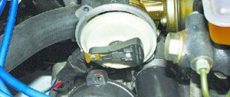
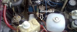
- Connect one of them to the machine ground, and the second to one of the coil terminals (the one from which the secondary voltage comes out).
- Scroll the distributor cap. Rotate until the lamp goes out.
- Put everything back in the same position and use the car.
As a rule, such a setting of the ignition timing of the VAZ-2107 gives good results and helps solve a number of problems - eliminate starting problems, reduce fuel consumption and even improve the dynamics of the car.
Design and principle of operation of the BZ
Contactless or electronic ignition on the VAZ 2107 is installed on models with injection engines. Carburetor sevens were supplied from the factory with contact ignition systems, which have many disadvantages. If you plan to install a contactless ignition module, then before starting it won’t hurt to understand the issue of its design.
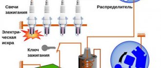
The ignition system is the mechanism by which a pulsed voltage is created to supply the spark plugs in order to promptly ignite the fuel-air mixture in the cylinders. The main disadvantage of contact SZ is that the contact groups require regular cleaning, replacement and adjustment. As soon as difficulties arose with igniting the combustible mixture, the car owner immediately knew where to look for the reasons.
With the advent of the BSZ, these difficulties automatically disappeared. To understand why, let’s look at the components of the mechanism:
- Electronic type switch with transistors.
- Double winding coil.
- A distributor or distributor equipped with a Hall sensor, a slider and a contact cover.
- Spark plugs with armored wires.
The BSZ diagram for the VAZ 2107 is shown in the photo below.
Ignition circuit for VAZ 2107
Based on this diagram, let's consider the principle of its operation:
- When you turn the ignition key, current is supplied to the primary winding of the coil, thereby creating a magnetic field.
- When the engine starts, power is supplied to the starter coil and the rotor begins to turn the crankshaft.
- In this case, the crankshaft rotates the distributor shaft, which is connected to the runner.
- As soon as the shaft with the slider rotates, this phenomenon is detected by the Hall sensor (along the protrusion on the shaft) and transmits the corresponding signal to the switch.
- When a signal arrives at the switch, the primary winding of the coil is de-energized (on the low-voltage side).
- A powerful discharge of about 25-30 kV is induced in the secondary (high-voltage) winding, transmitted to a moving contact located at the end of the distributor shaft.
- When the slider moves in a circle, it practically touches the contacts in the cover, a spark occurs between them, and a high voltage discharge is transmitted to each of the contacts in turn.
- This discharge flows through armored cables to the spark plug electrodes.
Pros and cons of the system
If you decide to install a carburetor-type BSZ on a VAZ 2107, then it is recommended that you first understand all the advantages and disadvantages of the device. The advantages of the mechanism under consideration include:
- The absence of contacts automatically eliminates the need for their maintenance. As a result, we have a more reliable system that does not require frequent maintenance.
- Stability of spark propagation through the cylinders, which is due to the absence of the breaking effect of the contacts using the cam method.
- A large discharge in the spark plug, the value of which reaches 25-30 kV, while in contact modules it does not exceed 12 kV. High voltage promotes a stronger spark and improved ignition of the fuel assembly, as well as its complete combustion.
- Simplified engine starting at low temperatures.
Contactless (electronic) ignition, carburetor
Many car owners are switching to a more accurate (electronic) type of ignition. To adjust the device yourself, you need to have skills in working with the electrical part of a car. If you do not have sufficient knowledge, entrust the work to experienced specialists.
Prepare the instrument for tuning. You will need keys (for “eight”, “ten” and “thirteen”), a Phillips screwdriver, a drill and a pair of self-tapping screws.
Pre-install the contactless system itself, consisting of the following elements:
Trambler. Start by replacing the distributor by lifting the cover of the latter (this is how you gain access to the “slider”). Place the slider in a position that can be easily adjusted during installation. It is desirable that the notch be on the block opposite the middle mark of the device scale.
Use a “thirteen” wrench to tighten the fastening nut, and then dismantle the assembly. Now disconnect the central wire connecting the coil and the distributor. Mount the non-contact type sensor and adjust the slider taking into account the previously made mark. Align the distributor body along the notches. Replace the cover and return the wires to their place.
Coil. In the next step, move on to the ignition coil. Take the eight key and twist the wires that are connected to the device. Now use the key to “ten” to push the assembly away from the car body.
Install the new coil taking into account the position of contacts “B” and “K”.
Fix the coil and connect the discarded and new wires to the contact group. Pay attention to the colors of the latter (as a rule, they are identical for the old and new devices). Connect the brown wire to terminal “K” and the blue wire to “B”. Now connect the center wire.
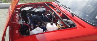
- Switch. Start by choosing a location for this node. In the "seven" the best point for installation is between the headlight on the left side and the washer. In this area there is a flat area on which the device is placed. To begin, lean the switch and mark the mounting locations. After this, screw in the screws. Do not rush to tighten the second fastener - place a black wire under it.
As soon as the described work is completed, check the quality of the connection of the wiring elements and start the engine. The next stage is installing the ignition of the VAZ-2107, which will be discussed below.
Ignition module
The ignition module is a device designed to convert DC voltage from the on-board network into high-voltage electronic pulses with their subsequent distribution between the cylinders in a certain order.
Design and operating principle
The design of the device includes two dual output ignition coils (transformers) and two high-voltage switches. The voltage supply to the primary windings of the transformer is controlled by the controller based on information received from the sensors.
In the ignition system of an injection engine, voltage distribution is carried out according to the principle of a spark at idle, which ensures a pairwise separation of the cylinders (1-4 and 2-3). A spark is generated simultaneously in two cylinders: in the cylinder where the compression stroke ends (power spark), and in the cylinder where the exhaust stroke begins (idle spark). In the first cylinder, the air-fuel mixture ignites, but in the fourth, where gases are exhausted, nothing happens. After starting the crankshaft half a turn (180 0), the second pair of cylinders is included in the process. Since the controller receives information about the exact position of the crankshaft from a special sensor, there are no problems with sparks and their order.
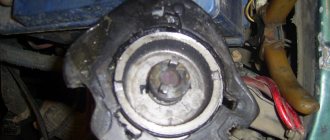
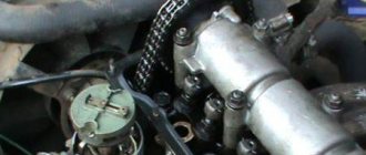
Location of the ignition module VAZ 2107
The ignition module is located on the front of the cylinder block above the oil filter. It is secured to a specially provided metal bracket with four screws. This can be determined by the high-voltage wires coming out of the housing.
Factory designations and characteristics
VAZ 2107 ignition modules have catalog number 2111-3705010. Alternatively, consider product numbers 2112-3705010, 55.3705, 042.3705, 46.01. 3705, 21.12370-5010. They all have approximately the same characteristics, but when purchasing a module you need to pay attention to the size of the motor for which it is intended.
Table: technical characteristics of the ignition module 2111–3705010
| Name | Index |
| Length, mm | 110 |
| Width, mm | 117 |
| Height, mm | 70 |
| Weight, g | 1320 |
| Rated voltage, V | 12 |
| Primary winding current, A | 6.4 |
| Secondary winding voltage, V | 28000 |
| Duration of spark discharge, ms (not less) | 1.5 |
| Spark discharge energy, MJ (not less) | fifty |
| Operating temperature range, 0 C | from -40 to + 130 |
| Approximate price, rub. (depending on manufacturer) | 600–1000 |
Ignition adjustment in static position:
- Find a strobe light. If this is not the case, do the work by ear.
- Loosen the nut holding the ignition coil.
- Start the engine and warm it up.
- Rotate the distributor housing left and right.
- Command your assistant to watch the speed (they should be at 2000 rpm).
- Listen to the engine noise. Try to catch the moments when there are “dips” or changes in rotation speed.
- Achieve a situation where the engine runs smoothly and produces the highest speed. In this case, the work should be as rhythmic as possible.
- Tighten the distributor nut and operate the car.
Setting the ignition timing of the VAZ-2107 in motion:
Remember that adjusting the advance angle may not be enough - often the carburetor itself needs to be adjusted. To do this, find a couple of screws. With one of them you regulate quality, and with the other you regulate quantity. Also clean the carburetor from time to time.
As can be seen from the described technique, setting up electronic ignition on the “seven” is not difficult. At the same time, you can count on serious savings, because at the service station this service will cost a considerable amount.
SPARK PLUG
Plugs are used to ignite the fuel-air mixture in the engine cylinders when high voltage is supplied from the ignition coil. The main elements of any spark plug are a metal body, a ceramic insulator, electrodes and a contact rod.
Spark plugs are necessary to generate a spark and ignite the fuel-air mixture in the engine cylinders
CHECKING SPARK PLUGS VAZ 2107
There are many ways to check spark plugs. The most popular are the following algorithms.
- With the engine running, remove the high-voltage wires one by one and listen to the operation of the engine. If after disconnecting the wire no changes occur, then the corresponding spark plug is faulty. This does not mean that it necessarily needs to be changed. In some cases, you can get by with cleaning it.
- The spark plug is unscrewed and a high-voltage wire is put on it. The spark plug body is leaned against a mass (for example, a valve cover) and the starter is cranked. If the part is working properly, the spark will be clear and bright.
- Sometimes spark plugs are checked with a special tool - a gun. The spark plug is inserted into a special hole and checked for the presence of a spark. If there is no spark, the spark plug is faulty.
You can check the serviceability of the spark plugs using a special tool - a gun - Candles can be checked with a homemade device made from a piezo lighter. The wire from the piezo module is extended and attached to the tip of the candle. The module is pressed against the spark plug body and the button is pressed. If there is no spark, replace the spark plug with a new one.
VIDEO: CHECKING SPARK PLUGS
SELECTION OF SPARK PLUGS FOR VAZ 2107
Various models of spark plugs are installed on VAZ 2107 carburetor and injection engines. In addition, the parameters of the spark plugs depend on the type of ignition system.
The choice of spark plugs for the VAZ 2107 is determined by both the ignition system and the engine type
Auto stores offer many types of spark plugs for the VAZ 2107, differing in technical characteristics, quality, manufacturer and price.
TABLE: CHARACTERISTICS OF CANDLES DEPENDING ON THE TYPE OF VAZ 2107 ENGINE
| For carburetor engines with contact ignition | For carburetor engines with contactless ignition | For injection 8-valve engines | For injection 16-valve engines | |
| Thread type | M 14/1.25 | M 14/1.25 | M 14/1.25 | M 14/1.25 |
| Thread length, mm | 19 mm | 19 mm | 19 mm | 19 mm |
| Heat number | 17 | 17 | 17 | 17 |
| Thermal enclosure | Stands for spark plug insulator | Stands for spark plug insulator | Stands for spark plug insulator | Stands for spark plug insulator |
| Gap between electrodes, mm | 0.5 – 0.7 mm | 0.7 - 0.8 mm | 0.9 – 1.0 mm | 0.9 – 1.1 mm |
You can install spark plugs from various manufacturers on VAZ cars.
TABLE: MANUFACTURERS OF SPARK PLUGS FOR VAZ 2107
| For carburetor engines with contact ignition | For carburetor engines with contactless ignition | For injection 8-valve engines | For injection 16-valve engines |
| A17DV (Russia) | A17DV-10 (Russia) | A17DVRM (Russia) | AU17DVRM (Russia) |
| A17DVM (Russia) | A17DVR (Russia) | AC DECO (USA) APP63 | AC DECO (USA) CFR2CLS |
| AUTOLITE (USA) 14–7D | AUTOLITE (USA) 64 | AUTOLITE (USA) 64 | AUTOLITE (USA) AP3923 |
| BERU (Germany) W7D | BERU (Germany) 14–7D, 14–7DU, 14R-7DU | BERU (Germany) 14R7DU | BERU (Germany) 14FR-7DU |
| BOSCH (Germany) W7D | BOSCH (Germany) W7D, WR7DC, WR7DP | BOSCH (Germany) WR7DC | BOSCH (Germany) WR7DCX, FR7DCU, FR7DPX |
| BRISK (Czech Republic) L15Y | BRISK (Italy) L15Y, L15YC, LR15Y | CHAMPION (England) RN9YC | CHAMPION (England) RC9YC |
| CHAMPION (England) N10Y | CHAMPION (England) N10Y, N9Y, N9YC, RN9Y | DENSO (Japan) W20EPR | DENSO (Japan) Q20PR-U11 |
| DENSO (Japan) W20EP | DENSO (Japan) W20EP, W20EPU, W20EXR | EYQUEM (France) RC52LS | EYQUEM (France) RFC52LS |
| NGK (Japan/France) BP6E | EYQUEM (France) 707LS, C52LS | MARELLI (Italy) F7LPR | MARELLI (Italy) 7LPR |
| HOLA (Netherlands) S12 | NGK (Japan/France) BP6E, BP6ES, BPR6E | NGK (Japan/France) BPR6ES | NGK (Japan/France) BPR6ES |
| MARELLI (Italy) FL7LP | MARELLI (Italy) FL7LP, F7LC, FL7LPR | FINVAL (Germany) F510 | FINVAL (Germany) F516 |
| FINVAL (Germany) F501 | FINVAL (Germany) F508 | HOLA (Netherlands) S14 | HOLA (Netherlands) 536 |
| WEEN (Netherlands/Japan) 121–1371 | HOLA (Netherlands) S13 | WEEN (Netherlands/Japan) 121–1370 | WEEN (Netherlands/Japan) 121–1372 |
Injector ignition
Often on forums there is a question about how to set the ignition on a VAZ-2107 with an injection engine. The answer in this case will be original - “no way.” The thing is that on a car with an injector, ignition adjustment is the task of the ECU. In this case, special sensors collect information. They determine the ignition timing, as well as other parameters, subsequently transmitting them to the main unit. All you have to do is ensure that the timing chain (belt) is properly tensioned. If problems do appear, the injector must be flushed and the failed components replaced.
What to do before setting the ignition
First you need to make sure that:
- all spark plugs are working, the gaps are adjusted, no carbon deposits are formed, the top is a spark plug with carbon deposits, the bottom is normal.
- armored wires have good insulation and contact with spark plugs;
- Check the contacts of the distributor to see if they are burnt. If they are burnt, they must be replaced;
- the contact and quality of the wire from the coil are good, is the ignition coil working?
- clean all dirt and dust from the coil, distributor cap and distributor contacts;
- Ignition adjustment must be performed with the engine fully warmed up.
Do-it-yourself ignition installation on a VAZ 2107
If the car engine starts intermittently, the dynamic parameters of the car have decreased or fuel consumption has increased, most likely the VAZ 2107 ignition needs to be installed. These are the signs that indicate problems in the module. This is a mechanism that converts electrical energy into a spark. The procedure depends on the type of system implemented on your car: injector or carburetor. It is not difficult, even an inexperienced craftsman can do it with his own hands if he has the tools, understands the process and the design features of the module.
Replacing the starter relay
Another common problem on VAZ 2107s with a carburetor is a malfunction of the starter relay. When you turn the key in the lock, the system makes a click, but the retractor relay does not operate. Replacing the relay is very simple.
First you need to remove the starter from the relay. Unscrew the 2 bolts that secure it. Slide it to the right and take it out, turning it backwards. Unscrew the nuts securing the starter and relay.
Turn it to the side.
Remove the 2 bolts securing the relay to the starter.
Install the new one in reverse order.
If you follow these simple steps, your VAZ 2107, which has a carburetor system, will serve you for many more years.
Tools you will need for your work
On a car with a carburetor, two ignition systems are used: contact and non-contact. In the first case, you need to prepare:
- strobe or regular 12V light bulb;
- open-end wrench 13;
- special wrenches for crankshaft
To install the contactless mechanism, you will need the following tools:
- Phillips screwdriver;
- keys for 8, 10 and 13;
- drill;
- self-tapping screws
Installing the ignition on a VAZ 2107 with an injector in the usual sense of this process is impossible, but you can check the module using a multimeter.
The cost of setting up the ignition of a VAZ 2107 at a car service center is quite affordable - on average 500 rubles as of February 13, 2022. But you will have to waste time and fuel traveling there and back. Therefore, the question of how to install this mechanism yourself is quite reasonable. Moreover, the whole procedure will take no more than half an hour.
HIGH VOLTAGE WIRES
High voltage wires (HVW) transmit impulses from the coil to the spark plugs. Unlike other wires, they must not only withstand high voltage, but also protect other parts of the car from it. Each wire consists of a conductor with a metal tip, rubber caps on both sides and insulation. The serviceability and reliability of the insulation is of great importance, since it:
- prevents moisture from entering the conductive element;
- reduces current leakage to a minimum.
FAULTS IN HIGH VOLTAGE WIRES
The following main malfunctions are characteristic of GDP:
- breakage of the conductive element;
- voltage leakage due to poor insulation;
- excessively high wire resistance;
- unreliable contact between the GDP and the spark plugs or its absence.
If the VV is damaged, the electrical contact is lost and a discharge occurs, leading to voltage loss. In this case, the spark plug receives not the rated voltage, but an electromagnetic pulse. Faulty wires lead to improper functioning of some sensors and interruptions in the operation of the power unit. As a result, one of the cylinders stops performing useful work and runs idle. The power unit loses power and begins to detonate. In this case, they say that the engine is “troubling.”
One of the malfunctions of high-voltage wires is a break
DIAGNOSTICS OF HIGH VOLTAGE WIRES
If you suspect a malfunction of the engine (the engine is “troubling”), they must first be carefully inspected - damage to the insulation, chips, or contact with hot engine elements is possible. Particular attention should be paid to the wire contacts - there should be no traces of oxidation or soot on them. If no visible damage is found, proceed to detect a possible break and measure the resistance of the GDP using a multimeter. The wire resistance should be 3–10 kOhm. If it is zero, the wire is broken. It should also be taken into account that the resistance should not deviate from the norm by more than 2–3 kOhm. Otherwise, the wire should be replaced.
SELECTION OF HIGH VOLTAGE WIRE
When purchasing new wires, you should pay attention to the car manufacturer's recommendations. The VAZ 2107 is usually equipped with VPPV-40 (blue) wires with distributed resistance (2550 +/-200 Ohm/m) or PVVP-8 (red) with distributed resistance (2000 +/-200 Ohm/m). An important indicator of GDP is the permissible voltage. If the actual voltage values exceed the permissible values, breakdown of the cable insulating layer may occur and the wire may fail. The voltage in a non-contact SZ reaches 20 kV, and the breakdown voltage is 50 kV.
The material from which the GDPs are made is also important. Typically the wire has polyethylene insulation in a polyvinyl chloride sheath. Silicone GDPs are considered the most reliable. They do not become rough in the cold, which prevents them from loosening in their nests, and are less prone to breakdowns. Wire manufacturers include Champion, Tesla, Horse, and others.
Tesla products are considered one of the most reliable
Procedure for operating a car with a carburetor
To set the ignition on a VAZ 2107, you do not need to create any special conditions. Work can be performed even outside during the cold season. Here is the ignition diagram for a car with a carburetor.
The sequence of operations on machines with contact and contactless modules is approximately the same:
- Work must begin with a cold engine. First, remove the wires from the spark plugs.
- Then the candles themselves are unscrewed. It's better to remove everything, so the crankshaft will move easier.
- Now close the place of the spark plug on the 1st cylinder with your finger in order to feel when the compression stroke in the cylinder begins.
- The key turns the crankshaft until the stroke begins.
- Continuing the rotation of the crankshaft, the ignition of the VAZ 2107 carburetor is installed according to the marks.
- Now you need to unclip the latches on the tumbler and check the direction of the slider. Its outer contact should be directed to the wire of the 1st cylinder.
Adjusting the ignition timing
For subsequent actions, use a 13 key to loosen the fastening nut of the distributor (ignition distributor). Connect one wire from the light bulb (it will act as a voltmeter, that is, indicate the presence of voltage) to the low-voltage terminal that the coil has, the second to ground.
Now turn on the ignition
Slowly and carefully rotate the distributor body clockwise, stopping immediately when the light goes out. The sparks that appear will indicate the moment of ignition
Move the distributor counterclockwise until the contacts are disconnected and the lamp lights up again. Everything is in order, you can safely tighten the distributor, the setup is complete.
Installation on a car with an injector
Manually setting the ignition of a VAZ 2107 injector using marks is impossible, since on such vehicles the adjustment is performed by the ECU (electronic control unit). It collects signals from sensors and, by comparing the readings of air flow, lambda probe, throttle valve and crankshaft position, determines the moment of spark formation. But if problems arise with the module, the motorist can independently check its performance. It is advisable to first familiarize yourself with the diagram.
The check is performed in the following sequence.
- All wires are disconnected from the ignition.
- The multimeter sets the maximum value to 20 kOhm.
- Resistance is measured in pairs: 2 and 3, 1 and 4.
- Performance indicators range from 3.6 to 4 kOhm. Any deviations indicate that the module is faulty and must be replaced.
How to install the ignition on a VAZ 2107 with a carburetor, watch this video:
About their device
Before finding out the importance of the elements of the ignition system in question, it is necessary to understand their structure. Structurally, the high-voltage wire consists of the following parts:
- A conductor through which current flows.
- Insulation - rubber or silicone is used as an insulating material.
- Protective caps on both ends.
- Metal contacts.
Each element performs corresponding tasks, and at the slightest violation of integrity, it will be necessary to replace it. Armored wires cannot be repaired, since they play one of the main roles in the car’s ignition system, and also belong to the category of consumables.
This is interesting! Few people know that on a car it is necessary to change not only the spark plugs, but also the armored wires, which wear out over time and begin to malfunction.
For distributor or MZ
Read, it may come in handy: Tuning the engine of the seventh model: a complete guide with photos and videos
It is a mistaken belief that armored wires on a car are ordinary wires that are designed to transmit current from a source to a receiver. As you know, VAZ 2107 cars were produced in two variations of the fuel supply system - carburetor and injector. Although many parts and mechanisms on the carburetor and injector are the same, this does not apply to the GDP. The carburetor VVP differs from the injection one on the VAZ 2107 in the following parameters:
- The length, on which the amount of resistance also depends. The wires on the injection unit are shorter than on the carburetor.
- Fasteners that connect to the distributor on the carburetor and the ignition module on the injector.
- The amount of GDP. There are four of them on the injector, and five on the carburetor.
- Type of caps.
Knowing the design differences, you must also understand that high voltage flows through the wire. The current comes from the distributor or MG through the wires to the spark plugs. The slightest malfunctions lead to the fact that current is not supplied to the spark plug, and a spark does not occur. If a spark does not occur, the cylinder does not work, which negatively affects the operation of the engine.
Let's summarize
The correctness of the work performed must be checked for the correct choice of the advance angle. To do this, you need to start the engine, if the engine starts without problems, accelerate the car to 45 km/h. At this speed, engage 4th gear and sharply press the gas pedal. If detonation occurs and lasts no more than 3 seconds, and disappears after acceleration, then the work has been completed correctly. If detonation does not appear, then you need to increase the angle, if it does not appear at all, reduce it.
Source
Adjusting the gap of the VAZ 2107 distributor breaker
The quality of the spark depends on the gap between the breaker contacts and the condition of the contacts themselves. To adjust the VAZ 2107 distributor, you must perform the following operations:
- unclip the fastening brackets and remove the distributor cover;
- unscrew the screws securing the slider;
- remove the slider;
- Clean the breaker contacts with sandpaper (to avoid damaging the contacts, you must use sandpaper with a grain size no larger than 600).
- loosen the screw securing the breaker contacts;
- turn the adjusting screw to set the gap to 0.4 mm, using the appropriate feeler gauge;
- tighten the fixing screw;
- install and secure the slider;
- fix the distributor cover.
In addition to adjustment, repair of the VAZ 2107 distributor may be required. This consists of cleaning the contacts on the distributor cover or replacing the cover itself, replacing the slider, resistor or contact group.
When should you turn on the ignition?
The first thing you should know is that there are no regulations for this operation, since the ignition timing is set or adjusted only if necessary. It may be caused by the following reasons:
- You recently purchased a “Seven” on the secondary market and are trying to “bring it to mind.”
- After engine repair, accompanied by its disassembly.
- After unscrewing or removing the main ignition distributor (distributor), regardless of the reason why this was done.
- When switching from high-octane fuel to gasoline with a lower octane number and vice versa.
- After replacing the contact group or bearing in the distributor (in cars with an old ignition system).
Note. On VAZ 2107 vehicles equipped with an electronically controlled injector, the reason for checking the spark generation system may be the flashing of the Check Engine display on the instrument panel. True, it behaves in a similar way when a dozen more malfunctions occur. So ignition problems must first be diagnosed by contacting a service station.
In the vast majority of cases, the sparking moment is set as a result of a violation of the settings after disassembling or repairing the engine. A separate issue is the transition to high-octane gasoline, which requires ignition with greater advance, for which adjustments are being made.
It is advisable to check the timely formation of a discharge on the electrodes of the spark plugs in cases where unstable engine operation is observed, popping noises are heard in the carburetor and exhaust pipe, accompanied by an increase in fuel consumption. If you have not yet discovered the “gluttony” of the car, then pay attention to the color of the smoke; with high gasoline consumption, it is black, as is the carbon deposits on the electrodes of the spark plugs.
Types of ignition timing
Acceleration dynamics, fuel consumption, trouble-free engine starting and exhaust toxicity of carburetor VAZ 2107 directly depend on correctly installed ignition. If the ignition system (IZ) of newer injection models does not require special adjustments, then cars with an older contact system require periodic adjustment.
- We accelerate the car to 40 km/h.
- We sharply press the accelerator pedal and listen to the sound of the engine.
- If noise appears and disappears when the speed increases to 60 km/h, then there is no need to adjust the SZ.
- If the noise and detonation do not disappear as the speed increases, then the ignition is early and requires adjustment.
If the ignition timing is set incorrectly, fuel consumption will increase and engine power will decrease. In addition, a number of other problems will arise - an incorrectly installed ignition will reduce the service life of the power unit.
If a spark forms on the spark plug earlier than expected, the expanding gases will begin to counteract the piston rising to the top position. In this case, they talk about early ignition. Due to too early ignition, the rising piston will expend more effort to compress the resulting gases.
This will lead to an increase in load not only on the crank mechanism, but also on the cylinder-piston group. If a spark appears after the piston passes the top dead center, then the energy generated from the combustion of the mixture enters the exhaust without performing any useful work. In this situation they say that the ignition is late.
The ignition system consists of the following elements: 1 - spark plugs; 2 — ignition distributor; 3 - capacitor; 4 — breaker cam; 5 - ignition coil; 6 — mounting block; 7 - ignition relay; 8 — ignition switch; A - to terminal “30” of the generator
To adjust the ignition of the VAZ 2107 you will need:
- key to 13;
- screwdriver;
- spark plug key;
- special key for crankshaft;
- vol (12V lamp).
- a ringing “metallic” sound has appeared in the engine operation, it is called “knock of fingers” when driving a car without load and acceleration;
- detonation, the car shakes for several seconds after the engine is turned off;
- Late ignition, retarded - a spark is formed in the cylinder after the piston passes the top dead center.
- Early, advanced - in this case, a spark is formed even before the piston appears at top dead center. With early ignition, the connecting rod and piston are faster, because the load on these components increases and carbon deposits appear.
Types of systems
For decades, while the VAZ 2107 model was produced (from 1982 to 2012), it was equipped with three types of ignition systems:
- mechanical with contacts - breakers;
- contactless;
- controlled by an electronic unit (ECU).
Contact ignition circuit installed in the first VAZ 2107 models
Note. The first 2 varieties were installed on the “seven” with a carburetor, the latter was introduced together with an injector.
In the mechanical version, the contacts opened by the cam of the distributor shaft break the low voltage circuit, initiating the formation of a powerful pulse in the secondary winding of the coil. This discharge is directed to the electrodes of the spark plug, which ignites the fuel in the cylinder where the piston has risen to top dead center (TDC) and the compression stroke is completed.
Scheme of non-contact ignition of the seven with a carburetor
The contactless circuit operates on the same principle, only the signal to break the circuit is supplied by the Hall sensor, and it is implemented by the switch. Therefore, setting the ignition on carburetor “sevens” is done almost identically. Another thing is cars with an injector, where a new system has been introduced that does not have not only contacts, but also a distributor and any moving parts. Here, the moment of spark formation is determined by the ECU controller, which is guided by the signals of various sensors.
Ignition system VAZ 2107 with injector
What is ignition timing?
For the ignition to work correctly, the following condition must be met: sparking must occur at the moment when the piston is at TDC. This should be a compression stroke. This moment should be the flash point.
Do-it-yourself carburetor adjustment for VAZ 2107
| Options | Classical | Contactless | |
| Spark energy | mJ | 20 | 60 |
| Secondary voltage rise time from 2 to 15 kV | mks | 30 | 20 |
| Secondary voltage max | kV | 26 | 29,5 |
| Spark duration | ms | 1,5 | 2 |
However, that's not all. The time it takes for the fuel mixture to completely burn must also be taken into account. Therefore, the spark plugs must create an impulse with some advance, which is called the advance angle. As a result, the mixture reaches the peak of combustion, and the cylinder begins to move downward.
If sparking occurs earlier, then such ignition is called earlier, and if late, then later. Early leads to detonation. This is why the engine quickly overheats and becomes inefficient, although fuel consumption can sometimes be greatly reduced. This can be determined by the spark plug electrodes, which are covered with a white coating. With late ignition, power is noticeably lost, and black smoke comes out of the exhaust pipe, which indicates that gasoline, without having time to burn in the cylinder, burns out in the exhaust system.
The spark plugs, in this case, turn black. Popping noises in the exhaust pipe can also tell this. Late ignition means that the spark plugs are simply flooded with fuel, which does not burn or burns incompletely. When they are flooded, they do not work.
Ignition systems are divided into 3 groups:
Electronic ignition system (microprocessor ignition system)
Electronic ignition system
Pros and cons of contactless ignition
| Pros + | Minuses - |
| Current is supplied to the ignition coils through a semiconductor switch to the primary winding, this makes the spark energy much greater due to the higher voltage on the secondary winding of the ignition coil (up to 10 kV). | The most significant disadvantage of this ignition system is its low reliability compared to others. The well-known switches that were initially installed on these systems were characterized by very low reliability and often failed. |
| Functionally replacing the CG, an electromagnetic pulse shaper made using a Hall sensor and which, compared to the CG, provides a significantly better pulse shape, as well as stability, throughout the entire engine speed range. In this regard, an engine equipped with BSZ produces significantly better power indicators and allows significant savings on fuel (up to 1 liter per 100 km). | If any problems arise, you will not be able to do without new spare parts. |
| A significant advantage of this ignition system is the low need for frequent adjustments and maintenance compared to KSZ. But as for servicing the system, everything is simple and comes down to lubricating the distributor shaft every 10 thousand km. mileage |
Pros and cons of contact ignition
| Pros + | Minuses - |
| This is the simplest ignition system, it can be repaired in an open field using a spool and a match within 10 minutes; this number will not work with a contactless number. Failure of the contact ignition system is unlikely. | Current is supplied to the primary winding of the ignition coil through a contact group. In connection with this, there is a significant limitation on the voltage on the secondary winding of the coil (up to 1.5 kV), which means there is strong spark formation. |
| Maintenance is required frequently. It is necessary to constantly monitor the gap in the CG, the angle of the closed state of the CG. It is necessary to constantly clean the KG contacts because they burn during operation. Also, the distributor shaft needs to be lubricated every ten thousand kilometers. It is also recommended to lubricate the distributor cam. | |
| The reliability of this system is low; it often breaks down and requires constant maintenance. |
| Pros + | Minuses - |
| A significant advantage of the MPSZ is that it provides high-quality ignition control depending on the crankshaft speed, pressure in the intake manifold, engine temperature, and carburetor throttle position. There is no mechanics in the system, so this ignition system produces a spark perfectly, the sparking is very powerful. | Cannot be repaired in the field. Difficult to find spare parts. Low reliability. |
Preparatory stage
To set the ignition on a VAZ 2107 car, no special conditions are required; the operation can be done both in the garage and on the street, including in winter. For work, prepare the following set of tools:
- flat screwdriver;
- metal probe 0.35 mm thick;
- open-end wrench size 13 mm;
- a car light bulb designed for a voltage of 12 V with wires soldered to it;
- a wrench with a long handle designed to turn the crankshaft;
- key for unscrewing spark plugs.
Ignition tuning tool
Note. Instead of a special key to rotate the crankshaft, you can use a regular open-end wrench measuring 36 mm. If you don’t have such a key, then you will have to set the marks in the old proven way: by engaging 4th gear and raising the rear wheel, turn it manually, thereby turning the crankshaft.
Ideally, it is better to have in your arsenal a device for setting the ignition on a running engine - a strobe light. It is equipped with a lamp that flashes simultaneously with the moment of spark formation in the cylinder, which allows you to see the position of the notch on the crankshaft pulley at idle speed and clearly adjust the advance angle.
This is what a strobe looks like, which is convenient for adjusting ignition timing
Important point. The ignition is set in order to ensure that the spark appears in a timely manner and the engine starts, after which additional adjustments will be required. But the latter will not bring you the desired result when there is no compression in the cylinders or problems with the carburetor make themselves felt. If these faults are not eliminated, the engine operation will remain unstable, no matter how you configure the spark generation system.
Hence the conclusion: you can set the ignition correctly at any time, but to set it well - only on a working engine and carburetor.
What is “ignition timing”
Ignition advance means the air-fuel mixture ignites before the piston reaches top dead center (TDC) during the compression stroke. This factor has a great influence on engine performance. A certain amount of time passes between the moment the spark occurs and the moment when the gas pressure in the cylinder reaches its apogee. Although this period of time is extremely short, due to the high speed of the crankshaft, during the time the mixture is ignited, the piston can travel a long way from the moment of sparking to the explosion of the mixture. When the advance angle is correctly set, the mixture explodes at the moment when the piston is at TDC and ready to move down. If the mixture ignites earlier (“pre-ignition”), it explodes during the lifting phase of the piston and interferes with the movement of the piston (the engine detonates). This leads to premature wear of parts and deterioration of engine performance. If ignition is done late (“late ignition”), the mixture explodes after the piston has left TDC, which leads to fuel burning out already in the exhaust manifold, a decrease in gas pressure in the cylinder and, therefore, loss of power and reduced efficiency. Therefore, installing the ignition on a VAZ 2107 is an important and necessary procedure. Sparking should occur at the most appropriate moment, which depends on the position of the gas pedal and crankshaft speed.
Tuning on carburetor modifications of the VAZ 2107
All old textbooks on servicing classic Zhiguli models describe a method for setting the moment of spark formation using a light bulb, although experienced motorists can easily do without it. You will understand why this happens as you read this material, but for beginners it will be useful to familiarize yourself with the old proven technique.
In order to check the performance of the carburetor or adjust its operation, it is recommended to read the following material: https://vazweb.ru/desyatka/dvigatel/remont-karbyuratora-vaz-2107.html
To correctly set the ignition of the “seven”, you need to ensure that the following conditions are met simultaneously:
- the notch on the crankshaft pulley is opposite the long mark on the timing cover;
- in this case, the round mark marked on the camshaft chain drive gear coincides with the boss on its body;
- the piston of the 4th cylinder has completed the compression stroke and is at top dead center;
- the contacts inside the distributor are open;
- The movable contact of the slider faces the fixed contact on the distributor cover, where the wire from the spark plug of the 4th cylinder is connected.
Note. On non-contact systems, at this moment the Hall sensor sends a signal to the switch to break the low voltage electrical circuit, which leads to the appearance of a high voltage pulse on the wire leading to the spark plug of the 4th cylinder.
The diagram shows what happens in the cylinders when the marks are aligned
The light bulb is used to control the ignition timing, for which it must be connected with one wire to the “K” contact of the high-voltage coil, and with the second to the vehicle ground. You should know that at the same moment the piston of the first cylinder is also in the TDC position, only there the air-fuel mixture is not compressed, but exhaust gases are released after its combustion. This is why ignorant car enthusiasts often confuse the first cylinder with the fourth when installing the ignition.
Layout of marks on the timing cover
When the above actions occur simultaneously, a spark discharge occurs on the electrodes of the spark plug of the 4th cylinder, as evidenced by the flash of the connected light bulb. To achieve these conditions and set the ignition correctly, follow the instructions:
- Turn the crankshaft with a 36 mm wrench, aligning the notch on the pulley with the long notch on the timing cover.
- If at this moment the engine valve cover is removed, then it is better to navigate by the mark on the camshaft gear, placing it opposite the housing boss.
- Take the ignition distributor, remove the cover and turn its shaft to place the slider opposite the wire leading to cylinder No. 4 (there are cylinder number markings on the cover). Insert the distributor into the engine hole, holding the slider and housing in this position, and then secure it with a 13 mm wrench nut.
- Connect the light bulb wires and turn on the ignition by turning the key. Loosen the nut securing the distributor and slowly turn it by the housing until the lamp flashes, indicating the moment of sparking. Reattach the distributor.
- Turn off the ignition and make sure that the contacts inside the distributor are currently open. Take a 0.35 mm feeler gauge and check the gap between them, if necessary, adjust it by loosening the fastening screws with a screwdriver.
The marks must be aligned by turning the crankshaft with a wrench
Note. The instructions imply that before starting work the distributor was removed from the engine without aligning the marks.
The ignition is considered to be set correctly if, after installing the distributor cap and connecting the wires, you manage to start the engine, and then you need to adjust the timing. The non-contact system is installed in the same way, with the exception of checking the gap in the contact group due to its absence.
The mark on the camshaft gear is aligned with the boss on the body
Important point. In most cases, the ignition is set without removing the valve cover, which is why the position of the mark on the gear is not visible. You have done everything according to the instructions, but the engine does not start. This means that a spark is supplied to the 4th cylinder during the exhaust stroke, and compression at this moment occurs in the first cylinder. The problem can be solved simply:
- remove the distributor cover;
- unscrew the nut securing it;
- pull the distributor out of the socket, turn the slider exactly 180° and insert the element back;
- Press the distributor skirt with the nut and install the cover.
Advice. If the engine does not start after these steps, but begins to show signs of life, then the problem lies not in the ignition setting, but in a malfunction of one of the system elements.
Photo instructions for setting up
Video about correct ignition installation
About assembling the timing belt and installing the chain according to the marks
As mentioned above, the timing system has a marking system that allows you to correctly install the guide sprockets and timing chain after replacement.
- If the timing chain was changed on a carburetor “seven”, then the oil pump sprocket, which was loosened above, is tightened first. In this case, the mark on the sprocket is aligned with the protrusion on the body (and if the “seven” is injection, this point does not play a big role).
- The chain guide and tension shoe are returned to their place.
- Now the crankshaft sprocket is put in place. It also has a recessed mark, which also needs to be aligned with the protrusion on the timing case, and only after that tighten the fastening nut on the sprocket and install the cotter pin in place.
- After aligning the crankshaft sprocket according to the marks, a new timing chain is put on it.
- Now all that remains is to install the camshaft sprocket in place. The asterisk does not tighten. The timing chain is put on it. In this case, the sprocket must be turned so that the mark on it coincides with the mark on the cylinder block. If there is no match, the chain should be removed from the teeth and the sprocket should be turned in the desired direction until the marks completely coincide.
Before tightening the sprocket on the camshaft, the marks must be carefully aligned - When the risks coincide, it is necessary to check the coincidence of the marks on the remaining sprockets. If there is no discrepancy between the marks, you can tighten the camshaft sprocket and install a cotter pin on it.
- Now all that remains is to return the timing cover to its place, and then replace the previously removed radiator.
More about the design and replacement of the timing chain damper: https://bumper.guru/klassicheskie-modeli-vaz/grm/grm-2107/uspokoitel-tsepi-vaz-2107.html
Video: how to install the timing chain according to the marks on a “classic”
Checking and adjusting the lead angle
To check whether the ignition is set correctly, just align the marks on the crankshaft pulley and the timing cover. In this case, the slider should be directed to the 4th cylinder, and the contacts should be open. If the slider “looks” towards the first cylinder and the car does not start, then turn it 180° as described above.
To create optimal fuel combustion conditions in the chamber, the flash should occur a little earlier than the piston reaches TDC. There are 3 ways to achieve this:
- when installing the ignition, align the notch on the pulley not with the first long mark, but with the second, indicating an advance angle of 5°;
- determine the amount of advance “by ear” by loosening the nut securing the distributor and turning it by the housing at idle engine speed;
- connect a strobe light to the system, start the engine and by turning the distributor, adjust the position of the notch by pointing the flashing lamp of the device at it.
The advance angle is adjusted by turning the distributor housing
Reference. The second method is most often used by experienced drivers, since it gives a positive result without any instruments. The ignition distributor is turned until the position of the most stable engine operation is found. That is why the use of a light bulb does not play a big role, because the real advance angle at which the engine operates in optimal mode lies in the range of 5-10° and is determined individually in each car experimentally.
Once the settings are complete, press the gas pedal sharply several times. If you can hear the piston pins knocking (a ringing sound is clearly audible from the engine), then the advance angle is too large. Loosen the distributor and turn it 1-2° clockwise, then check again by pressing the accelerator.
Advice. Finger tapping is often heard when you fill with low octane fuel. Then it is necessary to reduce the advance angle so that detonation (which causes knocking) does not destroy the piston group. When using high-quality fuel, the angle should be increased in order to improve the dynamic characteristics of the VAZ 2107.
The purpose of the timing chain and its length
To understand the purpose of the timing chain, it is necessary to outline what the engines of classic VAZ models are. All these engines are overhead engines. That is, the timing shaft (aka timing) is located in the upper part of the engine, above the crankshaft and above the oil pump shaft.
The timing chain is the main connecting link in the VAZ 2107 engine
All these shafts are equipped with sprockets, onto which the timing chain is placed. The chain's job is simple: it must transmit torque from the timing shaft to the crankshaft and to the oil pump shaft. From the crankshaft, torque is transmitted to the chassis, and from there to the drive wheels. They begin to rotate and the car moves forward. Thus, the timing chain is the most important connecting link between the three engine shafts, and any breakdown of this link will inevitably lead to either serious problems in the operation of the motor or to its complete jamming if the chain breaks.
Find out about the VAZ 2107 belt drive: https://bumper.guru/klassicheskie-modeli-vaz/grm/grm-2107/metki-grm-vaz-2107-inzhektor.html
Timing chain length for VAZ engines
If the driver decides to replace the timing chain on his “seven”, he will go to the spare parts store, where he will inevitably be faced with the question: which chain to choose?
You should know a simple rule: all engines on the VAZ “classic” are equipped only with chains. The only difference is in the length of the chains, or more precisely, in the number of links:
- chains with 114 links. They are installed on VAZ 2102, VAZ 2101 and VAZ 21011 (these short chains are designed for small engines - from 1.2 to 1.3 liters);
- chains with 116 links. They are installed on VAZ models from 2103 to 2107 inclusive. The same chains are installed on the Niva (VAZ 21213). The need for a longer chain is due to the increased volume of engines, which varies from 1.5 to 1.7 liters.
Based on all of the above, the driver in the store will have to determine what kind of chain he is buying - short or long. There are two ways to do this:
- The first way is obvious: simply count the number of links. If there are 116 of them, the chain for the VAZ 2107 has been found;
- the second method is simpler: you need to fold the chain in half, and then look at the pair of end links. If these links are symmetrical, then the chain has 116 links. If not, the chain is short, 114 links.
It should also be noted here that recently counterfeit timing chains have often been found on store shelves. Fortunately, the fakes are made rather carelessly, so an attentive car enthusiast can immediately suspect something is wrong.
Video: how to recognize a fake timing chain
How to set the ignition on a VAZ 2107 with an injector?
The ignition system of the “Seven” with direct fuel injection operates under the control of an ECU that receives signals from the following sensors:
- crankshaft position;
- air flow;
- throttle position;
- lambda probe.
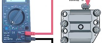
Multimeter for checking the ignition module
Based on the readings of these sensors, the controller itself determines the moment of spark formation, so the system is not configured in the usual sense. If any problems occur, the driver can only independently check the functionality of the ignition module, to which the high voltage wires from the cylinders are connected. To do this, you need to take a multimeter (ohmmeter) and perform the following steps:
- Disconnect all wires from the module.
- Set the maximum measurement value on the multimeter to 20 kOhm.
- Measure the resistance between the following pairs of terminals: 1 and 4, 2 and 3.
- If the measurement results fall outside the range of 3.6-4 kOhm, then the module is faulty and must be replaced.
The seven with an injector has an ignition module, which you can check yourself
Checking the module and adjusting the ignition of the VAZ 2107 (injector)
The VAZ 2107 ignition module (injector) is a unit whose malfunctions are quite difficult to diagnose. Problems with the module's operation are noticed only after serious engine malfunctions occur. If the engine does not start, you should try adjusting the ignition. If the engine is running unevenly, a serious check of the functionality of the VAZ 2107 ignition module may be required.
Ignition is an electronic system for converting the low voltage of the vehicle's on-board network into high voltage and supplying the latter to the electrodes of the spark plugs.
Checking the ignition system elements
Misfires in engine operation, especially in wet weather, are a consequence of breakdown of the insulation of high-voltage wires. There should be no cracks or damage in the wire insulation. You can check the insulation for breakdown using a wire connected to ground. If you run it along the insulation while the engine is running, a spark will be observed in places with damaged insulation. Another clear sign of poor insulation is noticeable electric shocks when touching high-voltage wires while the motor is running.
A broken high-voltage wire can be easily determined with an ohmmeter. The resistance should be between 3-10 kOhm. The spread of indicators between the wires should be no more than 1-2 kOhm.
Signs of breakdown
When the ignition is turned on, the engine ECU malfunction indicator light comes on, and after the engine is started, it should go out. A burning warning light is the first sign of problems with the ignition system. Other prerequisites for diagnosing the ignition module are “floating” engine speed and problems with starting. The cause of such failures may be faulty high-voltage wires or spark plugs, so you need to make sure they are working before you start diagnosing the ignition of the VAZ 2107 (injector). Often, cylinder misfires occur due to compression problems or damage to the intake manifold gasket. This must be taken into account when searching for the causes of engine failure.
Preparing for ignition diagnostics
To check the condition of the elements of the ignition system and the module as a whole, you will need a multimeter - a device designed to measure the electrical characteristics of the system (resistance, voltage, current). With its help, you can determine the voltage supplied by the module to the ignition coil, the serviceability of the coil and the reasons for the loss of current in the circuit. To make work easier, the ignition module can be removed externally.
Removing the ignition module VAZ 2107
- Remove the air filter housing.
- Disconnect the negative terminal from the battery.
- Remove the high-voltage wires from the ignition module cover.
- Unscrew the three nuts securing the VAZ 2107 ignition module and disconnect it from the bracket.
Checking the ignition coil
The coil is checked based on two indicators: the presence of a short circuit and an open circuit. Before diagnostics, the ignition coil must be disconnected. After this, one probe of the device is connected to the central contact of the coil, the second to the body (ground). If the display shows resistance equal to infinity, there is no short circuit.
The primary winding of the coil for a break occurs differently. The probes of the device must be connected to the right and left contacts. The resistance between them should be within 3-3.5 Ohms.
If the resistance of the primary winding does not correspond to the norm or there is a short circuit in the coil to the housing, it must be replaced.
Ignition adjustment
The injection modification of the VAZ 2107 does not require adjustment of the ignition timing. The electronic control unit, using a sensor, determines the optimal ignition timing. The participation of the car owner in adjusting the operation is limited to setting the engine timing belt to the marks.
To check the performance of the ECU and the functionality of the sensors, it is necessary to connect a computer with specialized software. In this way, the cause of most electronic ignition system malfunctions can be determined.
It is also worth checking the operation of the throttle position sensor yourself. When the throttle is closed, the voltage on the sensor should be no higher than 0.55 volts, and when fully open - 4.5 volts. Measurements must be made with a voltmeter with the ignition on.
Diagnostics of VAZ-2107 starter faults
- no rotor rotation;
- clicks when trying to start;
- extraneous sounds when the device is operating.
Starter won't start
The electric motor does not work due to battery discharge or winding failure. When the battery is discharged, the lighting devices do not turn on or the lamps glow dimly, and when you try to start the engine, a click is heard, after which the indicators go out.
Crackling sound when starting the starter
A cracking sound indicates a breakdown of the solenoid relay, which cannot engage the rotor gear with the flywheel ring. The repair consists of checking the wiring and measuring the resistance of the windings. A damaged relay must be replaced.
The starter clicks but does not turn over
The defect indicates insufficient voltage in the power supply due to battery discharge or oxidation of the contact pads. When the battery is low, the clicking sound is accompanied by a decrease in the brightness of the lamps. The defect is observed when there is poor contact between the battery contacts and the wiring terminals.
The starter hums but the engine does not start
The reason for the hum is that the bendix is jammed; the relay cannot move the gear to the flywheel. To check it is necessary to remove the electric motor. After cleaning the starter from dirt, performance is restored.
Ignition systems for VAZ-2101-2107 cars
Contact ignition system
The contact ignition system consists of an ignition switch, an ignition coil, a distributor-breaker, spark plugs, low and high voltage wires.
Ignition distributor 30.3706
The ignition distributor converts low-voltage direct current into pulsed current and distributes high-voltage current pulses across the spark plugs. It is structurally combined with a chopper and centrifugal and vacuum ignition timing regulators.
| rice. 1 |
The distributor is installed in the front of the cylinder block on the left side.
The distributor housing is cast from aluminum alloy. Two plain bearings are pressed into the housing shank, in which the roller rotates. A breaker cam is made on the top of the roller, and a centrifugal ignition timing regulator and rotor (runner) are also mounted. When the roller rotates, the weights of the centrifugal regulator diverge under the action of centrifugal forces and rotate the tetrahedral cam of the breaker at a certain angle in the direction of rotation of the roller. In this case, the contacts open with some advance, the greater the higher the engine speed. The rotation angle is limited by the size of the groove in the rotor support plate.
| rice. 2 |
The breaker consists of a stand with a fixed contact and a movable contact with a textolite stop, which is pressed by a flat spring to the tetrahedral cam of the distributor roller. When the cam rotates, the contacts close and open. The cam is lubricated with a felt fold soaked in engine oil.
When operating a car, it is necessary to systematically check and adjust the gap between the breaker contacts.
The plate on which the breaker mechanism is mounted is mounted on a ball bearing, allowing it to rotate around the axis of the roller.
The plate is connected by a rod to the diaphragm of the vacuum ignition timing regulator. The vacuum (supplied through the hose from the rear throttle space of the carburetor) acts on the diaphragm of the vacuum regulator, and the rod rotates the breaker mechanism together with the movable plate relative to the tetrahedral cam, thereby ensuring optimal ignition timing depending on the engine load.
To reduce sparking between the contacts of the breaker, a capacitor is connected in parallel with them. It is fixed externally to the distributor housing.
The top of the distributor housing is closed with a cover with sockets for high voltage wires. A spring-loaded carbon is mounted inside the lid into its central electrode. A rotor with a contact plate (runner) distributes high voltage current to the spark plugs in accordance with the firing order of the cylinders (1 - 3 - 4 - 2). The ignition distributor shaft rotates clockwise (when viewed from above).
When adjusting the ignition timing, turning the distributor housing clockwise reduces the timing, counterclockwise increases it.
Ignition coil B-117A
The ignition coil is a step-up transformer that converts low voltage pulse current (12V) into high voltage current. The coil windings are installed in a housing made of thin galvanized steel. The housing cover is made of insulating material, has two low-voltage terminals and a socket for a high-voltage wire. The coil body is filled with transformer oil, which cools the windings.
The ignition coil is installed in the engine compartment and secured to the left mudguard of the body with two nuts.
Ignition switch
The ignition switch is a combined switch, consisting of a lock with an anti-theft device and a contact part, assembled in one housing. The switch is installed on the left side of the steering column in a special bracket and secured with two screws.
Spark plug
The spark plug ignites the working mixture in the cylinder with a spark discharge. The design of the candle is non-separable.
For a properly functioning spark plug, the color of the central electrode insulator skirt should be gray or light brown.
| rice. 3 |
The car uses spark plugs A17DVR (A17DVRM) or their analogues.
What is electronic or contactless ignition?
The electronic or contactless ignition system is a more advanced version of the SZ for cars. The block of such a device is assembled from electronic elements. Contactless ignition on a VAZ is called that way, because in this case the circuit is closed and opened thanks to an electronic switch. The latter, in turn, operates from a transistor, and not from a distributor contact, as was before.
The electronic ignition circuit on a VAZ has minor differences depending on the type of engine - injector or carburetor. In any case, this option is in practice more modern, as a result of which its popularity among our compatriots is growing. Due to differences in the connection diagram and some differences for the injector and carburetor, some car owners believe that the BSZ and the electronic system are different components, but this is not so.
BSZ scheme for the domestic “seven”