To control the fuel in tanks, special devices are used: fuel level sensors, or FLS. They measure the amount of gasoline, oil or diesel fuel. Most often, FLS are installed on cars, but they are also in demand at fuel depots.
The sensor's task is to measure the fuel level, recalculate its volume and transmit information to the dispatcher. Thanks to the FLS, vehicle owners monitor fuel consumption and prevent gasoline from being drained: if at some point the fuel level in the tank drops sharply, the dispatcher will notice it. The sensor can complement other controllers or serve as an independent device, but it must be connected to the machine monitoring system. It is she who transmits and stores information about changes in the fuel level in the tank.
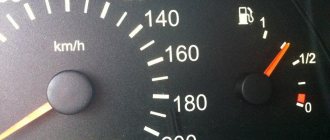
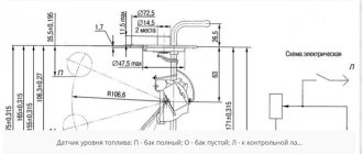
The FLS is installed through a standard hole in the tank or a hole of suitable diameter for installation is specially prepared. Most often, the device looks like a rod or a float, but this is high-precision equipment that can be used not only on passenger cars, but also on trucks, special equipment or stationary objects. The sensor can be connected to the fuel level indicator on the dashboard. Thanks to this, the driver can monitor consumption while driving and make timely stops for refueling.
What is a fuel level sensor
The FLS is a special device that determines the level of the fuel column in the tank. With its help, you can find out the exact volume of available gasoline or diesel, their consumption for a specific period and the time of refueling or draining. Such a sensor is installed not only on cars, but also on stationary objects.
The FLS operates in conjunction with the fuel level indicator located on the dashboard, where it transmits the received parameters. A GPS tracking platform will be required to display detailed information.
Operating principle of the fuel level sensor
How exactly the fuel level sensor works depends on its type. However, the basic principle of their operation is always identical. It is based on the constant determination of fuel residues using a special float, tubes or ultrasound. Each measuring element evaluates the level of gasoline or diesel in a special way and transmits the resulting parameters to the dashboard and monitoring system.
The output signal can be analog, frequency or digital. Each has its own characteristics and advantages. Analogue type FLS remain the most affordable, but they have poor protection against interference, which is why information is transmitted with a large error. Frequency signals conduct signals in encoded form, which somewhat improves the situation. Digital fuel level sensors have microprocessors and are better protected from interference, which allows them to demonstrate maximum accuracy.
Why is FLS necessary?
The cost of purchasing fuel is one of the largest items when maintaining a vehicle. Using a fuel level sensor helps not only record the amount of fuel at a given point in time, but also:
- determine fuel consumption for a certain time period;
- calculate average fuel consumption, for example, per hundred kilometers;
- control the timeliness of fuel refueling;
- identify unauthorized fuel drains and misuse of official vehicles.
All this allows for strict control of fuel consumption, finding ways to save money, and planning routes based on the available amount of fuel. Such measures help reduce the cost of purchasing fuel and maintaining the vehicle fleet as a whole.
Malfunctions and repairs
If the FLS is faulty, this affects the quality of measurements and the operation of the fuel level indicator. The arrow may “freeze” at zero, stop in place, or simply show incorrect parameters. To carry out independent repairs, you will need to study the circuit diagram of the fuel level sensor and dismantle it.
Main malfunctions and their elimination:
- wear of resistive elements - the problem can be solved by bending the “tongue”;
- movement of the board with resistive elements - you will need to solder the component in its place;
- disturbances in the electrical circuit - lubrication of components, as well as cleaning and tightening of contacts can help; an electrical diagram may be required;
- damage to wires - minor damage can be repaired using electrical tape;
- If the tube is dirty, just clean it and wash off the deposits with a special cleaning agent.
Any serious damage to the fuel control sensor requires replacement of the damaged elements. In most cases, it would be better to contact the service for full testing and repair. Capacitive fuel level meters are generally not subject to home inspection and require the attention of a specialist.
When several FLS are needed
There are cases when several fuel monitoring devices need to be installed on one vehicle:
- the presence of several fuel tanks. Freight transport usually uses two or even three tanks. In this case, fuel level sensors are installed in all containers, which allows you to get an accurate and complete picture of fuel consumption;
- the tank has an elongated shape (usually installed on car trailers). In this case, minor fuel fluctuations can negatively affect the accuracy of the readings. Therefore, it is advisable to install two (possibly more) sensors in different areas;
- the tank has a complex configuration (installed on agricultural machinery). Installing several devices that measure fuel level will ensure high accuracy of readings.
As for the connection interface, the owner makes the decision himself, based on his needs and financial capabilities.
Types of fuel level sensors
There are 3 types of fuel level sensors in the tank: float, capacitive and ultrasonic. Each of them has its own measurement characteristics and is distinguished by accuracy. As a rule, a float-based FLS is installed on cars from the factory, while capacitive and ultrasonic ones can be installed by GPS monitoring integrators.
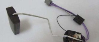
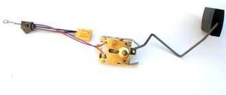
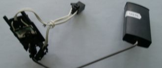
Float FLS
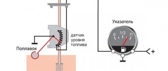
The float fuel level sensor is located inside the tank and only shows the approximate volume of fuel. The error in measurements can sometimes reach even 30%, which is why it cannot be called accurate. If the fuel level sensor is digital, then deviations from real indicators can be noticeably reduced. Most often they are installed on new car models.
Such a sensor determines the fuel level using a special float. An important component in the device is the potentiometer. When the amount of fuel in the tank changes, the float moves in the appropriate direction and affects the resistance of the resistor with voltage. New parameters are transmitted to the dashboard and contribute to the movement of the arrow in a certain direction.
Capacitive FLS
Capacitive type fuel level sensors are installed inside the tank. They are distinguished by high-precision measurements, the error of which does not exceed 2%. Such a FLS can be installed at GPS monitoring integrators.
According to the principle of operation, the capacitive type fuel level sensor is somewhat different from the float version. It contains two tubes, external and internal, which are attached to the device board and act as capacitor plates. They fall inside the tank and pass current. When the fuel level increases or decreases, the electrical capacitance of the sensor changes. These parameters allow you to determine how full the tank is.
Ultrasonic FLS
The ultrasonic fuel level sensor is installed from the outside of the tank and is only possible at the integrator’s service. It allows you to measure fuel volumes with high accuracy, without deviating from real indicators beyond 2%. However, the measurement results can be negatively affected by foreign elements or partitions inside the tank, unevenness of its walls and loose installation of the fuel level meter itself.
The device is a special emitter, which is placed on the central part of the bottom of the tank. During use, it creates ultrasonic pulses that travel throughout the container and return. The time spent on one travel cycle becomes the basis for automatically calculating the actual level of remaining fuel.
Introduction
There are many different ways to measure fuel levels in the world.
The variety of sensors - level meters is very large, from classic float to ultrasonic. They differ in operating principle, design and type of output signal. You can write dozens of articles about the principles of operation and design of these devices... We will now talk about the types of output signal. The sensor output signal can be analog, frequency or digital. Let's take a closer look at them.
Analog output signal
The analog signal is perhaps most often used when building sensors in general, and fuel level sensors are no exception. The vast majority of standard float level sensors have an analog signal at the output. An analog signal involves encoding level values with values of some physical quantity, most often voltage or current. If they say that the sensor has an analog signal from 0 to 10 volts at its output, then in general this means that an empty tank corresponds to a voltage of 0 V, a full tank corresponds to 10 V, and intermediate voltage values correspond to a level from empty to full. Simplicity and versatility are the main advantages of the analog output signal. For example, a value of 6 V corresponds to 60% of the height of the fuel level in the tank. It's simple! As they say, six volts, they are six volts in Africa. And any voltmeter or voltage meter (if, of course, it is working) will show that the signal is equal to five volts. But this is probably where the advantages of the analog signal end. Let's find out why.
The whole problem is the accuracy of the measurement, or, scientifically speaking, the error.
In general, error shows how different our idea of a parameter is from its real value. Simply put, how badly we misjudge.
The error can be absolute and relative. Absolute error is how much we are mistaken when estimating the inaccuracy in units of the measured value. Let us have a tank of fuel and we believe that it contains 20 liters. (in reality there are 24 liters.) The absolute error in this case is 4 liters. It also seems to be nothing complicated, only the absolute error does not give much. Well, we made a mistake by 4 liters, so what? Is it good or bad? If it’s a 40-liter tank on a VAZ 2104, that’s quite a lot, but if it’s a 400-liter tank on some truck tractor, then the estimate is very tolerable. If this is a twenty-cubic-meter container, then an absolute error of 4 liters is completely out of the realm of fantasy. Therefore, as a rule, they operate with the relative reduced error. Relative reduced error is the error expressed as a percentage of the measurement range. Or, more simply put, how many percent were we wrong? If we consider our example with an error of 4 liters, then for a tank with a volume of 40 liters the error is 10%, for a tank of 400 liters. - already 1%. Percentages can be compared, and a choice can be made between one or another measurement tool. It is believed that the smaller the relative error, the higher the measurement accuracy. This is where the catch lies! It consists in the fact that not everything is determined by the error of the measuring sensor. It is necessary to take into account a number of important factors that influence the final measurement accuracy. Let's try to figure this out. The author will try not to delve into the dense science called Metrology, but will try to explain everything in simple language and with examples. Because of this, the tone of my narration may not be entirely accurate, but respected metrologists from calibration laboratories and scientific institutes will forgive me.
So, the first thing you need to understand is that the measurement error is the sum of the errors of all converters and meters located in the measurement channel. The question immediately arises for the uninitiated reader: “What’s going on there? There’s only one sensor, that’s all!” No, not all. There are at least two meters in fuel level measurement. Fuel level value, i.e. millimeters of level are measured by a sensor. This is the first dimension. Next, the measured value is converted into an analog signal, and this voltage is transmitted through the wires and then measured by the receiver. This is the second dimension. As a result, the error of the entire measuring path is summed up from the error of the level meter, voltage meter, and sometimes it is necessary to add to them the error of level-to-voltage conversion, if it is not included in the total error of the sensor. And if each measurement or transformation has a relative reduced error of 1%, then the total error in the worst case will be 3%! This, by the way, explains the recommendation not to use devices with different values of the limit of the main reduced error in the same measuring channel. It makes no sense to use a voltmeter with an error limit of 1% to measure the signal from a sensor with an error limit of 0.01%. This is the same as measuring a part turned on a precision CNC machine with a wooden school ruler; the action is meaningless. As a rule, in life, the accuracy of the primary measurement - in our case this is measuring the fuel level - is worse than the accuracy of the secondary measurement - in our case this is measuring voltage. It makes no sense to make a sensor with an accuracy of 0.1% and connect it to a level recorder that has an analog input with an accuracy of 1%. The second very important point is the erroneous interpretation of the concept of “accuracy” and the confusion of different types of error.
All equipment manufacturers that work with analog signals declare some accuracy parameters. That’s exactly what they write: “Accuracy – 0.1%”. Someone indicates the error values, for example: “The relative error is no more than 0.5%.” Someone is more cunning and only indicates the bit depth of the analog-to-digital converter (ADC) something like this: “ADC - 10 bits, output value - 0 to 1024.” This implies that the value can be obtained with an accuracy of about 0.1% (if you divide 1024 values by 100%). All this, in general, only misleads the ignorant buyer. Let's try to understand what accuracy is and what it is formed from.
The measurement accuracy is the sum of the main reduced error and the additional error caused by the influence of some factors.
We have already talked a little about the main error shown, so we will not redefine it. It is obtained from the arithmetic sum of a number of partial errors: measurement error, transformation sampling error, intermediate recalculation error, nonlinearity error, hysteresis error, calibration error, time instability error due to element aging, etc. It is clear that it makes no sense for an ordinary consumer to understand all these “bells and whistles,” but it is necessary to understand that they exist. Take an example where some manufacturer indicates the ADC bit capacity. This is just an indication of the sampling error of the transformation. Those. A 10-bit ADC contributes about 0.1% to the main reduced error. But the same meter may have a nonlinearity of 2% or a meter error caused by the spread of parameters of radio elements of 1.5%. And its final relative error will not be 0.1%! At the output, such a sensor will actually have 1024 different values, only all of them will differ from the real one by several percent. Another component of the basic reduced error that you need to be aware of is the accuracy of the calibration or conversion. If you take a fairly accurate fuel level sensor, for which the other components of the main reduced error are, for example, no more than 0.25%, and then calibrate such a sensor with a tin bucket purchased at a hardware store, then what will be the final accuracy of measuring the volume of fuel? It’s even impossible to determine, because... The limit of the main reduced error is not marked on the tin bucket, and it is generally unrealistic to assess its contribution to the final volume readings. The same, by the way, applies to two-point calibration. Two-point calibration is generally suitable for tanks with the shape of an ideal parallelepiped, which do not exist in nature. The greater the deviation of the shape from the ideal, the higher the error.
Additional error is an error caused by the influence of something external on the meter or sensor. As a rule, only the influence of temperature is considered, because other factors, for example, solar wind, have a negligible effect.
A number of manufacturers indicate an additional percentage error for every 10 degrees. This means that in order to understand what final accuracy a meter or sensor will have at a certain operating temperature, it is necessary to calculate the additional error and add it to the main one. For example, it is indicated that the additional error is 0.05% for every 10°C. The change in temperature is considered from normal, usually equal to 25 ° C. Then, at an ambient temperature of -25 °C, the temperature change will be 50 °C, which will introduce an additional 0.25% error into the accuracy. And if the main error is 0.5%, then the total error (or the required accuracy) will be 0.75%.
A number of manufacturers (for example, Omnicomm), in order not to bother the user with such arithmetic, immediately indicate the main reduced error over the entire operating temperature range. Those. An additional error caused by temperature changes is added to the main error. And if it is indicated that the error is no more than 1% over the entire temperature range, it means that at any temperature the total error will be no more than this percentage. Although, for example, at a normal temperature of 25 ° C, the main reduced error of such a sensor, without the influence of an additional one, can be 0.5% or 0.25% or even less. The largest value of the sum of the main and additional errors is simply indicated at once.
A number of manufacturers generally bypass the values of additional errors and do not indicate them. Either considering that they simply do not exist (although no one can abolish Mother Nature with her laws yet), or allowing the consumer to determine in the field how temperature affects the meter or sensor. Well, let's leave it up to them.
The third thing you need to know is the discrepancy between the input range of the meter and the output range of the sensor. This discrepancy also greatly affects how accurate we ultimately get the measurement results. It must be understood that the value of the main reduced error is indicated for the entire measurement range (in fact, this is what the term “reduced” means). If we take a very precise metrological steel ruler one meter long and start measuring the sizes of gear wheels from a wristwatch with it, then it is clear that we will not achieve anything worthwhile. There are only millimeter marks on the ruler, but you need to measure microns. And the point is not that the ruler is inaccurate, but that we started measuring with the wrong thing... If we take a fuel level sensor with an output signal from 0 to 10 V and start measuring its value with a voltmeter, which has a basic reduced error limit of 0.1 %, but designed for the range from 0 to 100V, then we can measure values from 0 to 10V with an accuracy 10 times worse, i.e. already 1%. Therefore, when pairing different devices, their input and output ranges must be taken into account. If you take a navigator with an analog input, designed to measure voltage values from 0 to 30 V and having a good limit of the main reduced error of 0.5%, and attach to it a sensor with an output signal from 0 to 5 V, then the final accuracy (as well as discreteness) will be 6 times worse, i.e. not less than 3%. And if you cut such a level sensor, narrowing its output signal to, for example, 4 volts from the initial five, then the error will be even higher. Plus, you also need to add the sensor’s own basic reduced error (for example, 1%), plus an additional error due to temperature changes (if it is specified by the manufacturer), and also take into account the calibration error - for example, at two points... There's a lot of running. Let everyone draw their own conclusions for themselves. Some people will be okay with this, some won't.
Let's summarize. If you want to use a sensor with an analog output signal, you need to consider:
- the limit of the basic reduced error of both the sensor and what the sensor is connected to. If the main given error is not clearly indicated, then we must try to understand what is indicated. As already mentioned, sampling error is often passed off as the main error;
- error in calibration or other transformations;
- the value of the additional error from the temperature, again, of the sensor and meter;
- mismatch between output and input ranges. And how much these ranges narrow when sensors are trimmed.
Only the combination of all these factors will allow us to answer what kind of error will occur during the measurement.
Another disadvantage of the analog output signal is low noise immunity. Of course, modern solutions in the field of creating electronic components, well-developed Russian and international standards for electromagnetic compatibility (EMC) make it possible to create solutions that are practically not affected by electromagnetic interference. But not all manufacturers, in an effort to reduce the cost of a product, deal with similar issues. As a result, to all the components of measurement accuracy, those caused by interference are added. It is possible to measure and evaluate them only during operation, because in most cases, manufacturers do not provide any characteristics, and, unfortunately, their influence sometimes distorts the measurement result by an order of magnitude more than all the factors described above.
As a result, the low accuracy that inevitably occurs when working with an analog signal, if we honestly take into account all its components, and the low noise immunity pushed engineers to look for another way to transmit the measured value. And frequency and digital methods of transmitting the output signal appeared.
Frequency output signal
In the case of a frequency output signal, or frequency modulation signal, the output value is encoded by the frequency of the pulses in the communication line. The sensor error still remains, but, in fairness, it must be said that it is present in all methods of transmitting the output signal. The disadvantage of this method is its slowness. If we want to accurately transmit the output signal, then we need to increase the frequency (and this involves increased requirements for the source), or increase the transmission time (which leads to delay in the system). Again, in some cases this is acceptable, and in others it is not. Plus, there is an error in the data transmission channel caused by the need to convert the initial value (in our case, the fuel level value) into frequency. These shortcomings did not allow the frequency method of transmitting the output signal to become a standard and become widespread. The last of the disadvantages of this method is missing from the digital method of transmitting the value of the output signal. The frequency output signal is something intermediate between digital transmission and an analog signal. The output value is encoded by the pulse frequency in the communication line. The main advantage of this method is the still retained universality of the output signal, but the absence of meter error.
Digital output signal
It became possible to implement digital output of sensors after the development of microprocessor technology. Most modern sensors have a microprocessor that recalculates, linearizes, and equalizes the raw measurements. The microprocessor made it possible to reduce the main relative and additional errors of the sensor itself. And, naturally, the microprocessor digitally processes the values. What is the point of then converting this value back into an analog signal, transmitting it over a wire and digitizing it again at the receiver? A loss of accuracy and noise immunity is inevitable. This is done only to ensure compatibility of various receiving devices and sensors. As already mentioned, the analog signal is universal...
But if you coordinate the output of the sensor and the input of the data receiver at the protocol and interface level, then you can transmit measurement results directly in digital form, without losing accuracy and ensuring the proper level of noise immunity.
This is the main advantage of digital outputs: there is only one source of error in the measurement channel - the primary meter. For it, it is still necessary to take into account the main reduced and additional errors, but there is no need to worry about matching the input and output ranges, there is no error in the secondary measurement, there is no influence of interference. And therefore digital outputs are becoming increasingly developed and popular.
Conclusion
We looked at sensor interface options. They all have pros and cons. Decide for yourself which one to use. The author only hopes that this article has given you information and you can make the right choice.
Design features of FLS
Manufacturers sometimes change the design of fuel level sensors in some models, adding new elements to them. They are usually equipped with special components that add new functions or improve existing ones. The main meter circuit remains unchanged.
Remote control of FLS power supply
Sometimes the signal transmission from the fuel level meter stops. This happens for two reasons: a dead battery or a power outage. In some cases, unscrupulous drivers do this intentionally to drain fuel. The remote control function eliminates this situation and sends information to the fleet if the fuel sensors have been disabled.
Fuel temperature control
The temperature control function can even be present on ultrasonic fuel level sensors. It allows you to identify deviations in fuel heating and maintain the engine in good working order, but there is no practical use in it, since temperature indicators do not affect the service life of the machine.
Universal connection interface
The fuel level sensor with a universal connection interface allows you to choose between analogue and digital signals at any time. This feature is useful in cases where the device needs to be connected to an existing tracker or a whole batch of meters is purchased for a large fleet.
Fuel level indicator
The fuel indicator is located in the cockpit. It shows the exact amount of fuel remaining to control consumption. In some cases, the device has a disciplinary function. Using indicators in the cockpit, you can hint to an unscrupulous driver that the drain will be detected by the fuel level indicator and will lead to punishment.
FLS bend
If the gas tank has a complex shape, then a special FLS with the possibility of bending the measuring part may be required. Such models allow single bending at an angle of up to 70° without reducing the service life of the device.
CAN-like bus S6
The use of a CAN-like bus is being promoted in the FLS market as a means of creating a universal interface for connecting various devices in cars. Such devices with a fuel level meter transmit information via a CAN bus and provide a great advantage in the form of the ability to combine several sensors.
Explosion-proof version
FLS in explosion-proof design have a special design that provides increased safety. They are used on fuel tankers and other equipment transporting dangerous goods, where only such a fuel sensor can be installed by law.
Built-in GPS tracker in FLS
If your car does not require a full-fledged GPS monitoring system, but you need to track its location, then a FLS with a GPS tracker will be the best option. It helps to control fuel consumption and see the location of the car without purchasing additional expensive devices and saving space.
Calibration
When installing and cutting a capacitive fuel level meter, it will need to be calibrated. To do this, you need to set new parameters indicating the minimum and maximum volume of fuel. This can be done by simply measuring the fuel level in an empty and full tank.
Calibration process:
- Connect the FLS to the computer, first turning it over with the meter facing up.
- Fill the space between the tubes with the used fuel.
- When the indicators are recorded in the software on the computer, mark them with a full tank.
- Drain the fuel from the sensor, wait for stabilization in the software and mark the empty tank.
You can also perform the procedure using a reservoir, but this method will be much more complicated and require more time. Therefore, it is easier to use the available tools from the instructions above.
Modules - how it works
The sensor module measures the charging time. The more fuel in the tank, the higher the capacity of the sensor, which means it will take longer to charge. To create such a measuring device, use a built-in microcontroller (comparator). A portion of the voltage will be supplied to the input via a resistive motor. When the meter receives voltage, the microcontroller will work, and when the voltage reaches the peak level, the timer will start.
The timer readings will be transmitted to the reflection module. When making a homemade measuring device, clock the microcontroller with quartz at a frequency of 16 MHz. The sensor can be made from foil PCB. Glue the strips of foil together. Make the gap between the plates no more than one and a half millimeters. The length of the plates is at your discretion.
How to choose a sensor
When choosing a FLS, you should immediately decide what type it will be. Situations when it makes sense to install a float model are rare. As a rule, the choice is between an ultrasonic fuel level sensor and a capacitive one. There is no big difference between them, so the question is rather individual.
What to consider when choosing a FLS:
- Output signal type. It is recommended to give preference to digital devices operating using the RS-485 standard.
- Length of the meter in a capacitive FLS. If the device has too short tubes, the minimum fuel level will be displayed incorrectly.
- Additional functions. The need for functions that expand the capabilities of the device is determined individually.
- Enhanced power protection and galvanic isolation. Such parameters help maintain the functionality of the device after a power surge.
- Case material. Metal devices are more resistant to shock and provide protection from external electromagnetic influence.
It is also important to pay attention to the equipment and manufacturer of the device. The box must contain fasteners, gaskets and a seal. It is preferable to choose models from Bosch, Omnicomm, VDO or Italon. Especially in cases where an electronic FLS with additional functions is purchased. If you need to save money, you can consider options from AEB, Febi and JP Group.
Replacing the device
If you need to install a new fuel sensor by replacing the old one, then there is no need to go to a service center - you can perform the procedure yourself. You just need to have all the tools at hand.
How to replace the FLS:
- If the car is gasoline, you need to disconnect the negative terminal of the battery at the very beginning.
- Remove the luggage compartment trim and rear seats to gain access to the sensor.
- Remove the protective plate by twisting the screws and thoroughly wipe the surface, removing dirt around the sensor.
- Disconnect all connected electrical circuits, first leaving markings on each to prevent future errors.
- Tighten the screws securing the FLS and carefully disconnect the device. If the meter is installed in the fuel pump, it may need to be disassembled.
- Thoroughly clean the area where the new device will be installed from dirt and glue, ensuring a good seal.
- When installing the sensor, it is important to accurately align it with the gasket and, if necessary, carefully treat the gasket with glue.
- Perform all steps in reverse order, except for installing the trim and rear seats.
Once the connection is complete, diagnostics should be performed. First you need to fill the tank full and make sure that the arrow shows an increase in fuel volume. Then you need to drive at least 30 kilometers and check for leaks and smell of fuel. If everything is in order, then all that remains is to put the seats and trim back in place.
Most actions with the sensor can be done independently. However, you should not disassemble the device and repair it if you do not have experience working with similar devices. It is better to contact the service and get qualified help.