Types of starting devices
Having some skills in radio electronics, we assemble a starting device for a car with our own hands. We will show drawings and photos, but first we will decide on its type, since they are different. Regardless of the type, it is important for us, as users, that the PU can work without the help of a battery and starts the engine not at the limit of its capabilities, turning red and smoking, but working stably even in severe frost. This is the most important condition when choosing a ready-made charging and starting device or assembling it yourself.
There is no special pickle here. The mechanism can be one of four types:
- pulse;
- transformer;
- battery;
- capacitor.
The essence of the work of each of them ultimately comes down to supplying the on-board electrical network with a current of the required rating and voltage, 12 or 24 volts, depending on the type of electrical equipment on board.
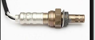
Checking the gaps between the electrodes
The spark plug is unscrewed and the hole is closed with a plug. Carbon deposits on a candle are removed by placing it in a bath of gasoline for several minutes. The insulator is cleaned with a special brush, the housing and electrodes with a metal scraper. The gap between the electrodes is checked with a feeler gauge: its value should be in the range of 0.5-0.75 millimeters. The gap is adjusted by bending the side electrode if necessary.
The serviceability of the spark plug is checked by connecting it to the magneto with wires and turning the crankshaft until a spark appears. After checking and servicing, the spark plug is returned to its place and tightened.
Transformer control panel, parameters
Transformer PUs are popular among DIYers. There is probably no need to explain the principle of their operation - it is a transformer that converts network electricity to the required parameters. These devices have one disadvantage - their enormous size and weight. But they are reliable and change the output parameters of voltage and current as needed. They are quite powerful and start the engine even with a dead battery. The simplest drawing for a transformer-based starter is shown below.
Classification of starter-chargers
Despite similar functions for starting internal combustion engines, ROMs come in several types in terms of design and mechanism.
Types of ROM:
- transformer;
- battery;
- capacitor;
- pulsed.
There are also factory models, among which you need to choose ROMs that start without a battery and work stably even in severe frost.
The output of each of them produces a current of a certain value and a voltage (U) of 12 or 24 V (depending on the device model).
Transformer ROMs are the most popular due to their reliability and repairability. However, among other types there are worthy models.
Transformer type
The operating principle of transformer ROMs is very simple. The transformer converts the mains U into a reduced variable, which is rectified by a diode bridge. After the diode bridge, the direct current with pulsating amplitude components is smoothed out by a capacitor filter. After the filter, the current rating is increased using various types of amplifiers made of transistors, thyristors and other elements. The main advantages of transformer type ROM are the following:
- reliability;
- high power;
- starting the car if the battery is “dead”;
- simple device;
- regulation of U values and current strength (I).
The disadvantages are its dimensions and weight. If you can’t buy one, then you need to assemble a starting charger for the car with your own hands. The transformer type has a fairly simple device (diagram 1).
Scheme 1 - Homemade starting device for a car.
To make a starter-charger with your own hands, the circuit of which includes a transformer and a rectifier, you need to find radio components or purchase them at a specialized store. Basic requirements for a transformer:
- power (P): 1.3−1.6 kW;
- U = 12−24 V (depending on the vehicle);
- winding current II: 100−200 A (the starter consumes about 100 A when rotating the crankshaft);
- area (S) of the magnetic circuit: 37 sq. cm;
- wire diameters of windings I and II: 2 and 10 sq. mm;
- the number of turns of winding II is selected during calculation.
Diodes are selected according to reference literature. They must be designed for large I and reverse U > 50 V (D161-D250).
If it is not possible to find a powerful transformer, then the circuit of a simple car starting-charging device will have to be complicated by adding an amplifier stage using a thyristor and transistors (scheme 2).
Scheme 2 - Do-it-yourself starting and charging with a power amplifier.
The principle of operation of a ROM with an amplifier is quite simple. It must be connected to the battery terminals. If the battery charge is normal, then U does not come from the ROM. However, if the battery is discharged, then the thyristor junction opens and the electrical equipment is powered by the ROM. If U increases to 12/24 V, then the thyristors close (the device turns off). There are two types of thyristor transformer ROMs:
- full-wave;
- pavement.
With a full-wave manufacturing circuit, you need to choose a thyristor of about 80 A, and with a bridge circuit, from 160 A and above. Diodes must be selected taking into account a current from 100 to 200 A. The KT3107 transistor can be replaced with a KT361 or another analogue with the same characteristics (it can be more powerful). Resistors located in the thyristor control circuit must have a power of at least 1 W.
Boosters and capacitors
Battery-type ROMs are called boosters and represent portable batteries that operate on the principle of a portable charger unit. They are domestic and professional. The main difference is the number of built-in batteries. Household ones have a capacity sufficient to start a car with a dead battery. It can only power one unit of equipment. Professional ones have a large capacity and are used to start not one car, but several.
We also recommend reading our expert’s article, which talks about how to choose a booster to start the engine.
Capacitors have a very complex design, and, therefore, it is unprofitable to make them yourself. The main part of the circuit is the capacitor block. Such models are expensive, but they are portable ROM, capable of starting the starter even with a “dead” battery. Frequent use causes the battery to wear out very quickly if it is new. The most popular among all models were Berkut (Figure 1) with starting currents of 300, 360, 820 A. The operating principle of the device is to quickly discharge the capacitor unit and this time is enough to start the internal combustion engine.
If you compare battery and capacitor ROM, you need to take into account the features of use in a specific situation. For example, when traveling around the city, the battery type is suitable. In the event that long trips occur, then you should choose an autonomous type of ROM, namely capacitor.
Devices based on switching power supplies
Another option is a pulse-type ROM (scheme 3). This device is capable of generating currents of up to 100 amperes or more (depending on the elemental base). The ROM is a switching power supply with a master oscillator on the IR2153 chip, the output of which is made in the form of an ordinary repeater based on the BD139/140 or its analogue. The switching power supply (hereinafter referred to as UPS) uses powerful transistor switches of the 20N60 type with a current of 90 A and a maximum U = 600 V. The circuit also contains a unipolar rectifier with powerful diodes.
Scheme 3 - Do-it-yourself portable starting device for a car with the ability to charge the battery.
When connected to the network through the circuit “R1 - R2 - R3 - diode bridge”, the electrolytic capacitors C1 and C2 are charged, the capacity of which is directly proportional to the power of the UPS (2 μ per 1 W). They must be designed for U = 400 V. The voltage for the pulse generator is supplied through R5, which grows over time across the capacitors and U on the microcircuit. If it reaches 11 - 13 V, then the microcircuit begins to generate pulses to control the transistors. In this case, U appears on II windings of the transformer and the composite transistor opens, power is supplied to the relay winding, which smoothly starts the starter. The relay response time is selected by the capacitor.
This ROM is equipped with protection against short circuit currents (SC) using resistors that act as fuses. During a short circuit, they open a low-power thyristor, which short-circuits the corresponding terminals of the microcircuit (it stops working). The disappearance of the short circuit is indicated by the LED that will light up. If there is no short circuit, then it will not burn.
How to choose a transformer
To make the device yourself, it is enough to find a suitable transformer, and for a reliable start it must produce at least 100 A and a voltage of 12 V, if we are talking about a passenger car. If you ask a fifth grader, he will be able to calculate the power. In our case, it is 1.2, or better yet 1.4 kW. Without a battery, it will hardly be possible to start the engine with such current, because the starter needs at least 200 A. A standard battery will help spin the crankshaft, and while rotating, the starter consumes no more than 100 A, which is what our device will produce.
The core area cannot be less than 37 cm², and the primary winding wire must be at least 2 mm². The secondary is wound with copper wire with a cross-section of 10 squares, and the number of turns is selected experimentally so that the open circuit voltage is no more than 13.9V.
Details
The charger and starting device uses a power transformer from the Rubin TV. It is also possible to use a TCA-270 type transformer. Before rewinding the secondary windings (the primary windings remain unchanged), the frames are separated from the iron, all former secondary windings (up to the screen foil) are removed, and the free space is wound with copper wire with a cross-section of 1.8...2.0 mm2 in one layer (up to filling) secondary windings. As a result of rewinding, the voltage of one winding should be approximately 15 ... 17 V.
Diagram and details of PU assembly
Calculating the parameters of a transformer is not all. The device works like this. We connect the power wires directly to the battery terminals, while there is no voltage at the output of the control unit until the battery voltage drops below the response threshold of the thyristors, which are indicated in the diagram. As soon as the voltage at the battery terminals drops, the thyristors open the input and only then the electrical equipment is powered by the device. As soon as the voltage at the battery terminals rises to 12 V, the thyristors close and the device automatically turns off. This allows you to save the battery from overload.
The thyristor version can be assembled using two methods - using a full-wave circuit and using a bridge circuit. If the rectifier is a bridge rectifier, then the thyristors must be selected twice as powerful. That is, according to the first scheme, thyristors are rated at a minimum of 80 A, and with a bridge circuit - at least 160 A. Diodes are rated for a current of at least 100 A. These elements are easily recognized by their braided output tip. The KT3107 transistor can be replaced with the 361st. There is only one requirement for resistance in the control circuit - their power must be at least one Watt.
The output wires, naturally, must correspond to the current and, as a rule, for this they take an analogue from a welding machine. Naturally, they are no thinner than the secondary wire. The wire that connects the network has a cross-section of each core of at least 2.5 square millimeters. A simple and reliable assembly that will start the engine in any frost. However, there are other options that you can buy in the store.
What parameters should a starter-charger have?
In order for the power unit to be guaranteed to start, it is necessary to calculate the parameters of the structural components used. At the output, the ROM must provide a current of at least 100 A, that is, power P = 1200 W. But there must be a reserve. Therefore, the output U = 14–16 V. It is worth noting that these are the minimum parameters with which the engine can be started, provided that the battery is at least a little bit still alive. The fact is that the starter requires energy up to 200 A at a time, and some of it is supplied by the battery. When the crankshaft begins to turn, the amount of current consumed drops by about half.
Selecting a simple transformer-based circuit
ROMs of any type perform the same task - they help start the car. However, when assembling a starting charger for a car with your own hands or buying it, it is worth remembering that there are several varieties of internal electronic filling:
- working on a transformer;
- delivering energy from a special separate battery (boosters);
- capacitor type;
- pulsed.
Since we are talking about the simplest ROMs that you can assemble with your own hands, we will further consider the first type of circuits listed above.
General information
Starting an internal combustion engine (ICE) in the cold season is a big problem. In addition, in the summer when the battery is dead, this is quite a difficult task. The cause is the battery. Its capacity depends on the service life and viscosity of the electrolyte. The condition or consistency of the electrolyte depends on the ambient temperature.
At low temperatures, it thickens and the chemical reactions necessary to power the starter slow down (the current decreases). Batteries very often fail in winter, since it is very difficult for the car to start, and more current is consumed than in the summer. To solve this problem, car starter-chargers (RODs) are used.
Don’t know how to make a winch from a starter with your own hands? Be sure to read the detailed and very interesting material from our expert.
Description and principle of operation of the starter-charger
There is nothing particularly complicated here. Mains U = 220 V is supplied through a switch to the primary winding of the transformer, and the alternating voltage is reduced on the secondary winding. Then it is smoothed out by a full-wave or bridge rectifier assembled using powerful diodes. The ripple voltage can then be filtered using electrolytic capacitors. If necessary, the voltage near the output is increased, which is done with the help of amplifiers, in which the main components are transistors and thyristors.
Among the disadvantages of the described starting-charger, one can note only its considerable weight, which is due to the installation of a powerful and, as a consequence, oversized transformer. Below is a diagram of a do-it-yourself full-wave starting-charger:
This circuit uses a laboratory transformer LATR. Instead of two diodes, you can also use a diode bridge of the KTs405 type. Starter-charger circuit for a car with an amplifier:
How to make a starter-charger with your own hands so that it will definitely work? Part parameters must be observed. The power of the thyristors shown in the picture is at least 80 A (if a diode bridge is used, then from 160 A). Diodes for current - 100–200 A. Transistor - KT361 or KT 3102 (any other with the same parameters can be used). The power of the resistors used is from 1 W.
A self-assembled charger and starting device is connected via alligator clips to the battery in accordance with the polarity. With a normally charged battery with ROM, no energy will be supplied. If the battery is not functioning, the thyristor junction will open, and the charging current will go to the battery and starter.
Calculation of transformer windings
First you need to select a magnetic core, the cross-section of which must be at least 37 square meters. cm. To calculate the number of turns in the primary winding, you need to use the formulas: T = 30/S, where S is the area of the magnetic circuit and N = 220*T, that is, W1 = 220*30/37 = 178 turns. For winding, it is necessary to use an insulated wire with a cross-section of at least 2 square meters. mm. Formula for the secondary winding: W2 = 16*T = 16*30/37 = 13 turns. Here you will need an aluminum tire with an area of 36 square meters. mm.
It is worth noting that formulas may not always give the exact number of windings (especially the secondary), so you can use the selection method. Having wound the primary winding, wind a few turns of the secondary and measure the resulting voltage without cutting the bus. Thus, you need to achieve a value of 14–16 V at the output.
Things will be easier if you have an LATR - laboratory transformer. You need to take the core from it. The number of turns of the primary winding is 265–295. Use 2mm insulated wire. Winding is done in three layers. Next, be sure to check the value of the no-load current (connect the multimeter to the gap between the 220 V network and one of the ends of the winding). The device should show 210–390 mA. If the readings are higher, the number of turns must be increased, otherwise, on the contrary, reduced. The secondary winding is divided into two sections, each with 15–18 turns. Here you will need a wire with a cross section of 10 square meters. mm.
Replacing the secondary winding of the transformer
First, using a chisel and hammer, you need to remove the secondary winding and its frame. Clean the edges of the windows from burrs with a file. Insulate the transformer rod, especially the corners, with a plastic plate. For the secondary winding it is necessary to have an insulated stranded copper wire with a cross-section of 10mm2. To obtain an output voltage in idle mode of 15V, it is necessary to wind seventeen turns, which corresponds to a wire length of about four meters. It is very difficult to place such a number of turns due to the large outer diameter of the conductor - 6.2 mm. To reduce the outer diameter of the wire, it is necessary to remove the insulation. Simply use a blade to cut through the insulation along the entire wire, and then peel off the insulation piece by piece and begin to insulate it in one layer with acetate fabric insulating tape. Now we have a new elastic wire with an outer diameter of 4.5mm. It is also necessary to prepare plastic spacers with a thickness of no more than 0.2 mm from various packaging containers, which must be placed between the layers during winding only inside the transformer window. It won’t hurt if you prepare in advance several wooden strips of different thicknesses to fix the turns while winding. After such preparation, you can begin winding the secondary winding. Once the desired number of turns have been placed, do not remove the remainder of the wire. Check the voltage at the winding terminals. The fact is that the parameters of the transformer may be different and depend on the number of welds.
Starter elements layout
The rectifier filter consists of a set of capacitors with a capacity of 2200 microns x 25V. Under no circumstances should you install one 10,000 micron capacitor with regular leads intended for printed circuit boards. The conclusions will simply become red hot, etc. You need to use a container whose terminals are designed for bolts. Such capacitors are quite expensive.
Supporting elements are needed only for ease of installation of diodes and the switch. The chassis consists of two layers: on the first layer of 2.5mm thick fiberglass laminate all components are installed, the second layer of laminite hides all the protrusions of the fasteners. After installing the rectifier, filter and transformer, we mount all this on the device niche and secure it with the screws that secure the rubber reinforcements. We carry out final installation.
Rectifier calculation
The following describes the parameters of electronic components (in addition to those indicated above) used in both circuits:
- Diodes. The maximum transmitted current should not be less than 100 A. These can be V200, D141, 2D141, 2D151 and other similar parts. Instead of KD105, it is not forbidden to use KD209 or even D226. Zener diode - D808, 2S182, etc.
- Thyristors. I = 80 A or more: TC185, T15-80, T15-100, T161, T125, etc. If the current rectification option with a diode bridge is used, the thyristors will be doubly powerful: T15, T160, T250, T16 and others, similar .
- Transistors. The gain factor h = 21e is important here. This is KT361 or KT3107 with npn conductivity. Instead of KT816, KT814 is also suitable.
- Resistors. It is desirable that their power be at least 1 W.
- Switch. Must keep current from 6 A.
Selection of wire cross-section
When selecting output wires that will be connected to the battery, you need to remember that their diameter cannot be less than the same parameter of the secondary winding. It is better to use a stranded copper cable used in welding machines, where each wire has a cross-section of 2.5 square meters. mm. The wire through which the homemade device will connect to the network must have the same area. Don't forget to purchase powerful alligator clips for connecting to the battery terminals. Here, too, it is recommended to use products used for welding (“mass”).
Troubleshooting Methods
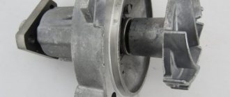
If the motor pump does not start, stalls under load, does not pump or pump in water, or does not start, you must carefully remove the impeller, disassemble it and adjust it. For each type of breakdown there is an individual solution to the problem
If it is impossible to start the motor pump, the following measures must be taken:
- filling fuel in strict accordance with the manufacturer's instructions;
- checking the fill level using a dipstick and, if necessary, carrying out additional fuel filling;
- horizontal placement of the device;
- checking the operation of the motor shaft using a starter cord;
- cleaning the carburetor float chamber;
- removal of contaminants in the fuel supply filter;
- complete closure of the carburetor damper;
- removing carbon deposits from the spark plug;
- installing a new spark plug;
- opening the fuel supply valve;
- cleaning filter devices by unscrewing the bottom plug on the float chamber.
If there are interruptions in the operation of the device, the following manipulations must be carried out:
- cleaning the filter and all approaches to it;
- installation of new filter parts and volute;
- determination of the nominal value of the rotor frequency;
- increase in pressure in the compressor.
In case of severe overheating of the engine, several actions must be taken:
- engine adjustment;
- compliance with the ambient temperature conditions when the device is operating.
Often, when performing work, the motor pump stops sucking liquid and pumping water. If this problem occurs, there is an established algorithm of actions:
- adding water to the pump part;
- hermetically sealed filler plug;
- replacement of seals and oil seal;
- replacing the suction hose;
- sealing places where air flows penetrate.
Over time, many owners of motor pumps notice a decrease in the volume of pumped liquid and a sharp drop in the performance of the device. Fixing this breakdown consists of several manipulations:
- checking the connection of the intake hose to the pumping equipment;
- fixing the fastening clamps on the pipe;
- washing filter parts;
- connecting a hose of the appropriate diameter and length;
- moving the installation to the water mirror.
To eliminate a breakdown of the time relay, it is enough to clean the internal equipment of contaminants, add the missing amount of oil and check the integrity of all parts. To resume silent operation of the motor pump, it is necessary to check the absence of mechanical damage and various defects in component parts. Only service center electricians can repair damage caused by the device being disconnected. Before calling a specialist, you can only check the junction box for the possibility of a voltage drop and remove visible soil particles inside the device.
Description and principle of operation of the starter-charger
There is nothing particularly complicated here. Mains U = 220 V is supplied through a switch to the primary winding of the transformer, and the alternating voltage is reduced on the secondary winding. Then it is smoothed out by a full-wave or bridge rectifier assembled using powerful diodes. The ripple voltage can then be filtered using electrolytic capacitors. If necessary, the voltage near the output is increased, which is done with the help of amplifiers, in which the main components are transistors and thyristors.
Among the disadvantages of the described starting-charger, one can note only its considerable weight, which is due to the installation of a powerful and, as a consequence, oversized transformer. Below is a diagram of a do-it-yourself full-wave starting-charger:
This circuit uses a laboratory transformer LATR. Instead of two diodes, you can also use a diode bridge of the KTs405 type. Starter-charger circuit for a car with an amplifier:
Let's sum it up
Finally, we would like to add that even a ready-made injection kit cannot be used normally without first fine-tuning the injection or carburetor engine. In other words, additional manipulations with the composition of the mixture (depletion or enrichment), an increase in air pressure during boost, correction of ignition to an earlier stage, etc. will be required.
It turns out that buying a ready-made kit or making water injection yourself cannot be considered a ready-made solution. It is much more important to correctly configure the engine and the system itself, taking into account the dosed supply of a high-quality atomized mixture of distilled water and methanol.
Mobile control units
Another type of PU, or rather two at once, similar in principle of operation - battery and capacitor. A capacitor device works by discharging charged capacitors upon command. Their composition cannot be called particularly complex, but capacitors of such ratings themselves are quite expensive and cannot be restored after damage or drying out. They are used very rarely, although they are quite mobile, but due to high unregulated currents there is a risk of harming the battery.
Boosters, or battery starters, work even simpler. By and large, this is just an additional battery in a self-contained case. It was their autonomy that brought them popularity. They can be used even in the steppe, where there is no electricity. The pre-charged battery is connected to the on-board power supply and quietly starts the engine. In this case, it is important to choose the booster capacity and its starting current. It cannot be less than that of a standard battery. Household autonomous units have a capacity of 18 A/h, while more expensive and bulky, professional devices can have a capacity of about 200 A/h.
Any of these driver assistants will help start the engine, but there is nothing more reliable and cheaper than a transformer PU assembled by yourself. Good luck to everyone and have a quick start!
Features of starting the engine in winter conditions
In winter it can be difficult to start the engine. The oil thickens, which means it is more difficult to turn it. The battery also fails frequently.
At sub-zero temperatures, the internal resistance of the battery increases, the battery drains faster, and is also reluctant to deliver the required starting current. To successfully start the engine in winter, the battery must be fully charged and not frozen. Additionally, you need to monitor the contacts on the terminals.
Here are some tips to help start your engine in winter:
- Before turning on the starter when cold, turn on the high beams for a few seconds. This will start chemical processes in the battery, so to speak, “wake up” the battery.
- Do not turn the starter for more than 10 seconds. This way the battery drains quickly, especially in the cold.
- Depress the clutch pedal fully so that the starter does not have to turn additional gears in the viscous transmission oil.
- Sometimes special aerosols or “starter fluids” that are injected into the air intake can help. If the engine is in good condition, it will start.
Thousands of drivers start their engines every day and go on business. Getting started is possible thanks to the coordinated operation of the engine starting system. Knowing its structure, you can not only start the engine in a variety of conditions, but also select the necessary components in accordance with the requirements specifically for your car.
Disadvantages and advantages of simple homemade starter-chargers
The main advantages of transformer ROM:
- ease of assembly and high reliability;
- power;
- the possibility of using used parts, which significantly reduces the cost of the design;
- starting the engine with an almost “dead” battery;
- low price: even if all the elements are purchased in a store, the cost of a homemade ROM will be several times less than the factory one.
What about the downsides? First of all, we can call it a large mass. However, this is not critical: it is unlikely that anyone will carry this device with them - its place is in the garage, in a “hospital”.
There is another negative side: in the simplest circuits of starting-chargers for car batteries, there is no protection against short circuits, overloads, or polarity reversals, which can lead to failure of both the ROM itself and the car’s electronics. The lack of control instruments - ammeter, voltmeter - also has a bad effect on the operation of the simplest ROMs.
Another disadvantage: more complex charging and starting circuits for car batteries are beyond the capabilities of a person familiar with the basics of radio engineering. Also, the device will not fully function if the network is significantly less than 220 V, and this is not at all uncommon in rural areas. The problem can be solved by using a stabilizer.
What should you consider when choosing a ROM?
Despite the fact that over a period of time a certain rating of starter-charger models has been formed, which can be found below, the most popular and popular model is not always suitable in each specific case. When purchasing a device, you need to base it on your needs, situation and capabilities. To choose the most suitable ROM, you need to consider several basic characteristics, which are described in detail below.
Maximum starting current
One of the most important parameters that you need to pay attention to when choosing a starting charger is the magnitude of the starting current. This indicator is measured in amperes and shows the amount of charge that is transferred to the battery when using the device.
To choose the most suitable model, you need to start from the engine size of the car for which you are purchasing the device. For small cars, a device with a starting current of up to 200 amperes is sufficient. If the engine is larger, then it is better to give preference to a ROM with a starting current of 300 amperes.
Support voltage
As for the output voltage indicator, it is recommended to purchase a device with this indicator of 19 Volts. Despite the fact that the vehicle's on-board network operates at a voltage of 12 volts, in the case where it is impossible to start the engine due to a discharged battery, a higher voltage will be required, even when starting the engine normally.
Dimensions and weight
Such parameters of the ROM depend on the further conditions of its operation. If a car enthusiast has a garage and there is no need to have the device with him all the time, then it is better to purchase a more powerful ROM, which can weigh on average 20 kg.
If a car enthusiast does not use a garage, but leaves his car in the parking lot and prefers to have the ROM with him, then the best option is to purchase a lighter and more portable device, the weight of which does not exceed 10 kg, and the width and height are 20 and 40 cm, respectively.
Additional options and features
Regarding various additional functions, it would not be a bad idea to purchase a device equipped with various protection systems, for example, if the car owner mixed up the terminals when connecting the device to the car’s on-board network.
It is also worth giving preference to devices that allow you to regulate current and voltage indicators. Using this function, you can independently select the required value depending on the situation and the condition of the battery.
When purchasing, you should pay attention to the material from which the device body is made. It is better to give preference to devices with a metal body or made of high-strength plastic
Such models can last for a long time.
Modification of the standard distributor. Experience. A lot of
Next we move on to the centrifugal regulator (CRZ).
To do this, the shaft with the central control unit must be pulled out of the distributor body, and at the same time try not to disturb the spring tension adjustment. Next, remove the springs, remembering where they were. We take a file and begin to grind down the side of the window in which the pin moves, limiting the value of the maximum ignition timing. You need to grind off about 2 mm, and be sure to check that the weights do not catch on the walls of the distributor body in their extreme, maximum stroke. If they catch, then it is necessary to slightly sharpen the weights themselves in the places of engagement until this is eliminated. After this, we assemble the distributor, not forgetting to lubricate the shaft-housing assembly with CIATIM, CV joint, LITOL lubricant, and install it on the engine. If the vacuum is adjusted, then there is a larger angle at the bottoms. If the vacuum is adjusted, then there is a larger angle at the bottoms. Vacuum does not work from revolutions, but from load
"Re: Hello." What does the turnover have to do with it? Or have I mixed something up again? :))The vacuum works when the vacuum in the intake manifold increases. And it doesn’t matter at what speed. Depends on the load. When we try to move off at idle, the vacuum valve works first. And then... when the speed increases, it’s a centrifugal. If I’m wrong, convince me otherwise. Best regards, Vladimir
If we look at the entire system as a whole, taking into account the fact that changing the SOP is necessary to ensure that the point of maximum pressure in the cylinder is in a strictly defined place (always in the region of 12-15 degrees after TDC) and the fact that the composition of the mixture that prepares the carb, is not constant at different values of mass air flow (this dependence can be seen, for example, in Erokhov’s book “Carburetors of Passenger Cars”), then it can be understood that the CBR provides correction of the OZ according to the speed of movement of the piston in the cylinder (more precisely, the time from the moment ignition to TDC), and VR - correction of the fuel consumption according to the composition of the mixture (this correction is necessary because a lean mixture burns slower than a rich one)
When experimenting with a distributor, however, one should not forget that exceeding the SOP at high speeds is fraught with the occurrence of glow ignition and overheating of individual parts, primarily valve plates and pistons, which can lead to their overheating.
Full-scale experiments with Silych at one time showed that without a compensation delay (where, when installed, the distributor moves forward by 6-8 degrees), when driving for a long time along the highway at high speeds, the engine begins to heat up and pulls worse, which led to the need to forcibly reduce the SOP at high speeds .
Yes it is. But the fact is that the combustion process is somewhat more complicated than it seems at first glance. There are two phases - the formation of the front and its expansion from the candle to the walls
And from a certain moment it doesn’t matter how long it takes to spread, everything depends on the formation of the front. By the way, the dependence of the optimal SOP on the speed is nonlinear and reaches some saturation
Moreover, noticeably earlier than the engine reaches maximum power.
In general, the speed limitation of the gas burner is determined by the physics of the combustion process and, without understanding it thoroughly, there is no need to split hairs here.
Source