Print this article Font size 16
The chassis of the VAZ 2114 includes two suspensions - front and rear. When driving a car, a large load is applied to the chassis, therefore the level of comfort and safety of the driver, his passengers and the transport around you directly depends on the condition of the suspension.
Rack kit
Each suspension performs the same role - it eliminates all kinds of vibrations and makes the ride softer. Plus, it is responsible for reducing roll when entering corners. Trips become smoother and more accurate.
Considering the quality of our roads, the cars really are not to be envied, since the front suspension of the VAZ 2114 experiences incredible loads, just like the rear.
Some people prefer the services of service centers, others do their own VAZ 2114 suspension repairs. What exactly you choose is up to you. Let's just say that on such a car, repairing or replacing suspension elements yourself is not as difficult as it might seem at first glance.
Today we will look at the design of the front suspension of the VAZ 2114, as well as the nuances of replacing it. We will go a similar way with the rear suspension.
Front suspension device
Suspension type: independent, telescopic. Let's take a closer look at the main components and elements that make up the front suspension of the VAZ 2114.
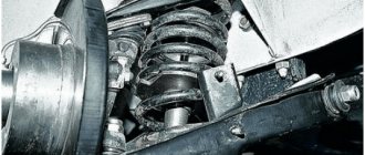
- The basis is the main rotating support element - the front pillar. Assembled into a single unit with a cylindrical spring, a swivel bearing, and upper and lower support cups. The strut is attached to the steering knuckle of the hub with the lower bracket, secured to the body with three bolts at the top and rests against the glass with the upper cup. Has a steering knuckle for attaching a tie rod pin.
- Front hub assembly with ball joint, double row bearing, brake disc and caliper. The ball joint is fixedly screwed to the lower suspension arm, the support pin is inserted into the seat at the bottom of the hub and screwed with a nut.
- The lower suspension arm is attached to a brace, which is attached at both ends to the body side member using two brackets. On one side of the brace there is an attachment point for the anti-roll bar, in which one end is fixed. The second end of the stabilizer is fixed to the suspension extension of the second front wheel, thus connecting them together.
Front suspension diagram for VAZ 2114
The front suspension diagram is shown in Fig. 1. The front chassis works according to the following principle: a strut with a spring plays the role of a supporting and at the same time shock-absorbing element for the front wheel. The stretcher and the lower arm support the entire assembly from below and prevent it from moving along the axis of the car.
The wheel is turned by a steering rod, which pulls the eye on the stand and turns the entire assembly, while at the top it turns on a support bearing, and at the bottom on a ball joint. The anti-roll bar ties the suspension on both sides together and makes it work in sync.
Stabilizer
This element of the front suspension of the VAZ-2114 is designed to reduce the roll of the car when cornering. The part does not have a complex structure and consists of a flexible beam, as well as a pair of silicone silent blocks. The element has a small stroke, which ensures vehicle stability on the road.
Attached to the front side members with the central part. The side parts are connected to the suspension arm on the “knuckles”. The stabilizer has a long service life - more than 100 thousand kilometers.
Usually it is the silent blocks that fail. But to replace them you need to remove the stabilizer completely. Below we will tell you how to do this.
Rear element design
Suspension type: dependent, on a rigid transverse continuous beam. The structural elements of the rear suspension and the methods of their connection in the VAZ 2114 are as follows.
- The base is a cross beam. The structure is welded, in the shape of the letter “H”, only with a long cross member. The two front ends of the beam are secured to brackets bolted to the rear side members of the vehicle. The method of connection to the brackets is hinged, on rubber-metal bushings. The rear ends of the beam have mounting flanges for wheel hubs. The hubs are bolted to the flange; a protective casing, brake cylinder and pads are mounted on them. Inside the hub there is a double row radial bearing. The brake drum is mounted on top of the pads and secured to the hub with guide pins.
- The lower end of the strut with a cylindrical spring is attached to the rear ends of the beam on the other side of the hubs. The upper end of the shock absorber rests against a glass welded to the body through a rubber spacer.
Rear suspension diagram for VAZ 2114
The rear suspension diagram is shown in Fig. 2. The rear chassis of the VAZ 2114 car operates as follows: the transverse beam works like a swinging pendulum, the attachments to the side members do not allow it to move along the axis of the car. Racks with springs attached to the opposite end of the pendulum limit its up-and-down movement and serve as a shock-absorbing and partially supporting element for the wheels.
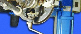
How does the ball joint change?
To do this, you need to remove the front wheel mounting bolts and hang part of the car on a jack. Next, the nut securing the ball element is unscrewed. The support pin is pressed out of the lever.
Similar to the previous case, this is done using a puller. If there is none, do not unscrew the nut completely. We press the lever with a pry bar and apply light blows with a hammer along the axis of the lever.
Use a wooden block as a buffer. The next step is to unscrew the two bolts that secure the ball joint to the steering knuckle.
After this, the lever is moved to the side (with a pry bar), and the support is successfully pulled out. A working finger should not move with more than 0.8 millimeters of play in the support. Otherwise, it needs to be replaced, since there is a large output here.
Before installing the dirt boot, it is recommended to coat the surface of the support with sealant. This way we will eliminate its premature delamination and deformation. It would also be a good idea to check the presence of lubricant in the ball.
Some manufacturers save money and use very little lubricant. In this case, we purchase a specialized product and coat the entire perimeter of the element with it.
Brief description of faults
In most cases, chassis repairs can be done yourself. The main malfunctions, as a rule, are associated with the failure of the shock-absorbing front and rear struts, since they are the most loaded structural element. The racks absorb dynamic loads from the car body, from the wheels when overcoming uneven road surfaces and lateral loads from the influence of steering rods, which increases at low speeds.
Two tools are required to remove and install the stands. The remaining tools are in every car enthusiast's garage:
- spring ties;
- a puller for pushing the steering rod pin out of the lever; it can also be used to press out the ball joint if necessary.
Smaller suspension malfunctions occur due to wear of the rubber seals and rubber-metal bushings (silent blocks). They are much easier to replace than a stand, although sometimes a device is also needed to press out silent blocks.
After repairing the front suspension, it is recommended to visit the nearest service station and perform an operation to correct the wheel alignment of the car. The chassis of the Lada 2114 has a fairly reliable and time-tested design, which is well adapted to our roads.
The front suspension of the VAZ-2114 receives the full load of the body, as well as not only the weight of the engine itself, but also the load force of the transported cargo. Therefore, this element must be very durable. Not many motorists know how the front suspension works, its elements, as well as the nuances of its operation.
How to replace the lever?
To do this, raise the front part of the car (alternately on each side with a jack). Next, unscrew the nut securing the ball joint and, using a puller, remove the ball joint pin from the lever. Next, unscrew the nut securing the extension.
The stabilizer link is disconnected from the lever. Next, unscrew the nut that secures the suspension arm to the body. If it is sour, use a “liquid key”.
At the next stage, you can safely remove the lever from the stretch outward. The new part is installed in the reverse order.
What's included in the front suspension?
The front suspension of the VAZ-2114 consists of many elements, but many motorists have encountered repairing them individually, and not as a whole system. The front suspension assembly is replaced if the car is involved in a traffic accident and almost all of its elements are destroyed.
So, it’s worth considering what the car’s front suspension consists of, to see what elements are included.
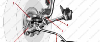
Vehicle suspension device
Design and decoding of VAZ-2114 suspension elements:
1 – upper support of the telescopic stand; 2 – upper support cup; 3 – compression stroke buffer with protective casing; 4 – compression buffer support; 5 – suspension spring; 6 – lower spring support cup; 7 – steering rod ball joint; 8 – steering knuckle; 9 – telescopic stand; 10 – eccentric washer; 11 – adjusting bolt; 12 – rack bracket; 13 – steering knuckle; 14 – front brake protective cover; 15 – brake disc; 16 – retaining ring; 17 – wheel hub nut; 18 – splined shank of the wheel drive hinge housing; 19 – guide pin; 20 – wheel hub bearing; 21 – ball joint; 22 – suspension arm; 23 – adjusting washers; 24 – stabilizer strut; 25 – stabilizer bar; 26 – stabilizer bar cushion; 27 – stabilizer bar mounting bracket; 28 – body bracket for mounting the suspension arm; 29 – suspension arm extension; 30 – bracket for fastening the extension; 31 – protective cover of the ball pin; 32 – ball pin bearing; 33 – ball pin; 34 – ball pin body; 35 – suspension strut rod; 36 – outer body of the upper support; 37 – inner body of the upper support; 38 – upper support bearing; 39 – rubber element of the upper support; 40 – travel limiter of the upper support; 41 – protective cap of the upper support; B - zone for monitoring the suspension joint.
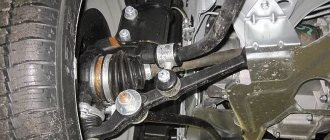
Individual elements of the front suspension
Front suspension elements
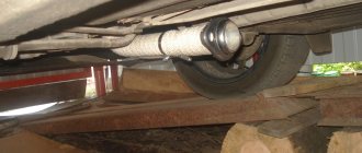
Front suspension view from below
As can be seen from the figure above, the suspension is quite simple, but all elements are interconnected and for repair and replacement, it is often necessary to disconnect other parts. Therefore, we will consider the main elements of the front suspension separately, and also indicate the main purpose of the part.
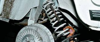
Front shock absorber strut
Front shock absorbers
The front shock absorber or front suspension strut is one of the main elements. This part provides shock absorption and absorption of uneven road surfaces. Also, it bears all the force that is in the car, including the load.
Usually, if this element is frequently loaded or incorrectly replaced, it has an increased degree of wear. Therefore, all motorists need to know the structure and operating rules of the shock absorber strut.
Let's look at how the shock absorber strut is designed, as well as all the structural elements:
Diagram of the shock absorber strut structure
1 – compression valve body; 2 – compression valve discs; 3 – throttle disk of the compression valve; 4 – compression valve plate; 5 – compression valve spring; 6 – compression valve cage; 7 – recoil valve nut; 8 – recoil valve spring; 9 – recoil valve plate; 10 – recoil valve disc; 11 – throttle disk of the recoil valve; 12 – piston; 13 – bypass valve plate; 14 – bypass valve spring; 15 – plunger; 16 – plunger spring; 17 – rod guide bushing with a fluoroplastic layer; 18 – guide bushing cage; 19 – sealing ring of the rack housing; 20 – rod seal; 21 – oil seal cage; 22 – gasket of the rod protective ring; 23 – rod protective ring; 24 – nut of the strut body; 25 – compression buffer support; 26 – rod; 27 – spring cup; 28 – rotary lever; 29 – rod limit sleeve; 30 – rack body; 31 – cylinder; 32 – drain tube.
Front stabilizer
A stabilizer is a suspension element that provides lateral stability while driving, especially when turning . This part is the least likely to fail.
It is fixed on special silicone or polyurethane bushings, which, as a rule, are consumables .
Front stabilizer installed on a car
The stabilizer is attached to the body, or more precisely to the front side members, with the central part, and the side elements are included in the stabilizer strut, which is attached to the lever.
It has a small stroke, which contributes to the car having lateral stability.
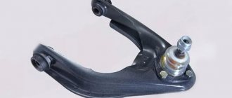
Lever arm
Front suspension arms
Detailed suspension repair diagram
In order to disassemble the suspension you will need quite a lot of tools: a set of keys and sockets, hammers, crowbars, pullers, and also screwdrivers.
So, let's look at a brief diagram of how to disassemble the suspension of a VAZ-2114 car:
- The car must be placed on a lift. Of course, you can use the inspection hole, but this is quite inconvenient and not entirely safe, since dismantling will be carried out on both sides at the same time.
- The first step is to dismantle the caps (if any), disks and loosen the wheel bearing fastenings.
- Next, disconnect the ball joint and also remove the steering rod.
- Unscrew the fastening and remove the stabilizer.
- The next step is to dismantle the lever.
- We remove the caliper.
- We remove the outer CV joint from the hub.
- Now you can remove the brake drum from the steering knuckle mountings.
- We dismantle the steering knuckle.
- Remove the shock absorber strut assembly.
- We disassemble the removed parts.
- Assembly is carried out in reverse order.
Thus, the entire suspension assembly can be replaced. If we take time, then complete disassembly of the VAZ-2114 suspension will take approximately 8-12 hours, if no difficulties arise. Some “kulibins” make it easier to speed up the process, and if the suspension to be removed will no longer be installed. It is worth noting that this method is dangerous and contrary to safety regulations, especially if the motorist has never performed this process. Let's briefly look at how the accelerated process occurs:
- Unscrew the stabilizer.
- We dismantle the upper mount of the shock absorber struts.
- Unscrew the steering rod and brake hoses.
- Carefully unscrew the lever mount.
- The suspension feeds downwards in the assembly.
Tuning
Tuning suspension for VAZ-2114
Many motorists, in order to improve the stability and maneuverability of the car, install a sports version of the suspension, both rear and front.
and “DVT-sport” offer a complete version of the front chassis assembly of the sports version. This kit is specially designed for the 2108-21099 and 2113-2115 car families.
It fits perfectly into the seats and is attached to the body without requiring any modifications. The sports suspension has greater stability and maneuverability, and can also withstand a load on the suspension that is 2 times greater than the standard one. The cost of this option is about 30-40 thousand rubles.
Tuning suspension installed on a car
How to replace?
Usually the racks are replaced in pairs or as a whole. To do this, jack up the front of the car and remove the wheels. Next, release the rack from its mounting with the steering tip.
Then unscrew the two nuts that secure the shock absorber to the suspension arms. The bolts are removed by hand from the reverse side. If they are rusty, you can use a hammer and attach a wooden block.
In this case, you should hold the stand from below so that it does not fall. After this, the suspension module is removed entirely. A new element is installed in its place.
Assembly is carried out in reverse order.