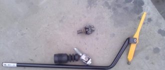
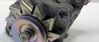
VAZ 2110 backstage and oil seal replacement
It is noteworthy that on the VAZ 2110 the rocker seal must be replaced when there is an oil leak from the gearbox. Replacing the VAZ 2110 rocker seal can be done in two ways, which will be discussed in this article. One of the ways to replace the cuff cuff involves dismantling the gearbox. The second method is not so cumbersome and is carried out directly on the car without removing the box. Needless to say, this method requires knowledge of certain secrets and skills.
Adjustment
You still need to engage first gear and drive onto the overpass. Naturally, put the car on the handbrake and put wheel chocks under the wheels. Don't turn off first gear!
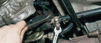
From below, find the clamp that secures the rocker and loosen it. Returning to the car, you need to move the lever to the left as far as you can. You cannot move the lever back or forward; the link may come off.
Go back under the car and tighten the clamp. Sometimes it is enough to move the rocker relative to the cardan by a few millimeters, and the gearbox will work perfectly again, gear shifts will occur as expected.
Preparation
If the listed symptoms appear, it is necessary to conduct an independent inspection of the drive.
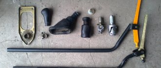
Prepare a set of wrenches, a hammer, a pry bar, screwdrivers, a chisel, and pliers. Organize workplace lighting. Place the car over the inspection hole (overpass; lift the front part with a jack, place safety supports). Place chocks on the outside of the wheels. Disconnect the negative terminal of the battery. The check begins in the salon.
Provide access to the floor tunnel.
For ease of operation and to avoid damage or contamination of the upholstery, dismantle the passenger seat:
- remove the torsion bars from the front side with a pry bar, unscrew the nuts, remove the fastenings of the tubular stop;
- Unscrew the bolts of the runners from behind, move, tilt the seat back;
- Unscrew the front fasteners of the guides and take out the chair.
Disassemble the floor tunnel:
- unscrew the self-tapping screws of the right and left facing panels;
- disconnect the handle with the casing;
- remove the four screws of the top cover, the plastic plug, lift it, pull it slightly back, lay it on its side;
- disconnect the wires, sign, attach marking tags, remove the box;
- Unscrew the nut and remove the metal air duct;
- Unscrew the four retaining nuts and remove the bottom of the tunnel structure.
Tuning
Many VAZ 2110 car owners, even having purchased a completely new car, strive to change the scenes. This can make it more comfortable, but only if done carefully.
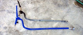
The fact is that the short-stroke rocker is, in fact, a homemade product, a modification. If you have a short-throw shifter, the gearbox wears out less, and in general this is not bad for the gears - they engage more clearly.
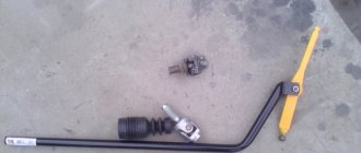
In order for the short-stroke rocker to replace the standard one, it does not have to be completely removed. It is enough for the ball joint to be disassembled from the outside. It is necessary to unclench the metal ring of the support and spread the plastic legs so that the ball comes out.
Next, you need to disconnect the rod from the support and weld a small piece of pipe to the rod, as well as a piece of durable sheet metal. Do not forget to lift up the hinge, which has a hook, to prevent the gears from being engaged by mistake.
Although the short-throw rocker requires more effort to engage, it increases the smoothness and clarity of gear engagement. But, in principle, choosing which is better for him - short-stroke or full-time - is the right of every VAZ 2110 owner.
DEVICE OF BRAKE MECHANISMS
Many people wonder what is the difference between the brake mechanisms of the front wheels and the rear ones. The fact is that when braking, they are subject to different loads, and they do not operate synchronously. But this is not the main reason for the differences.
The front mechanisms consist of:
- Brake disc of classic design;
- Direction pads;
- Calipers;
- Directly the pads themselves;
- Cylinder;
- Piston;
- Seal rings;
- Protection casing;
- Direction finger;
- And its cover, which performs a protective function.
The design of the front brakes is a little simpler than the rear, however, this does not mean that they play a lesser role in braking. After all, these are the mechanisms that work first.
- Nuts that secure the hub;
- Actually, the hub itself;
- Tension springs (lower and upper);
- Brake pads;
- Directional springs;
- Wheel cylinder;
- Expansion bar;
- Handbrake lever finger;
- Handbrake lever;
- Mechanism casing.
As we can see, this difference in design is caused by the presence of parking brake elements in the rear mechanism. Therefore, the part itself looks much more massive. The operating principle of the hydraulic part is the same as in the front. The only difference between the rear brakes is this.
A simple diagram of the VAZ 2114 brake system allows you to easily carry out any repairs yourself. Spare parts for domestic cars are inexpensive and quite common, which greatly simplifies operation and repair work. This is why VAZ cars are in such demand and provide good competition to foreign cars.
Repair or replacement
Before deciding whether repair, adjustment or replacement of the link is necessary, it will have to be disassembled.
- Remove the cover on the gear shift knob;
- The machine must be installed on a jack or on an overpass (pit);
- Remove the front console, which is bolted on;
- Remove the rocker by unscrewing 6 bolts.
During this procedure, carefully inspect all parts. You definitely need to bend the boot and inspect the condition of the support, cardan shaft, and oil seal.
It may be necessary to use a rem. kit, and perhaps a more complex repair is needed.
If the bushing is deformed, it needs replacement. If the cardan has play, as well as if the hole in the lever axis is worn, a complete replacement of the link and repair belt is necessary. the kit clearly won't help.
The reasons why the gearshift lever may dangle and play are discussed in this material: https://vazweb.ru/desyatka/salon/boltaetsya-rychag-kpp.html
It happens that the rocker pad is to blame for the rattling noise when changing gears. Replacing a pillow is a simple operation, but can be beneficial.
Why the reverse gear on the VAZ 2109 does not engage. Learning how to repair a gearbox
- the car is running), the clamp on the rocker is loosened, and the lever is moved to where it should be according to the schedule. The clamp is tightened, the success of the adjustment is checked with the engine running;
- If the knob is not set to reverse speed, the adjustment is made in first gear. The lever is moved to position 1, the clamp is loosened again, the rocker drive rotates against the clock until the gear shift lever hits the reverse speed lock.
Find the correct one in the fuse box, marked F21. He is 8th from the left; if it is burnt out, replace it; Raise the cover on the gearshift knob
There is a connector that is connected to the switch, you need to carefully disconnect it; The connector contacts are closed directly. If the missing gear appears, we change the switch, if not, we dig further; The connector is removed from the solenoid, and the voltage is measured in it
It should be 12 V, you can throw in a 5-watt light bulb to control it.
Replacing the rocker rod oil seal
The normal condition of the oil seal determines whether the oil “disappears” from the gearbox, so if you notice oil stains on the asphalt after parking, you should think about whether it is the oil seal or the oil filter.
Therefore, after checking the filter, it’s the seal’s turn. A malfunction of the VAZ 2110 oil seal can also be suspected if a crunching sound is heard when changing gears.
The oil seal can only be replaced in a hole, overpass or other device that allows you to get under the car:
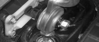
- First of all, we pay attention to the rubber boot. If oil escapes from the VAZ 2110 gearbox through the oil seal, then the entire boot will be in its drops;
- We bend the boot and disconnect the cardan, gaining access to the cuff;
- We remove the cardan from the lever, and then from the rocker;
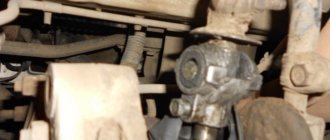
- Having removed the cardan, we get to the oil seal;
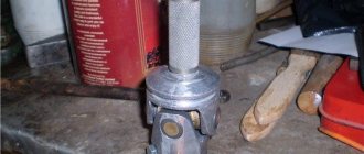
- Using an awl and a hook, remove the cuff on the gearbox;
- Now you need to press in the new oil seal. Traditional craftsmen usually install it using a plastic bottle cap;
- If the replacement was successful, we return everything to its place, install the boot, and we can consider this minor repair complete.
Procedure
On Renault Logan cars, the weak point is the left inner boot. It often leaks and quickly loses its protective qualities. Replacing the left CV joint boot on a Logan is carried out in the following order:
- Unclench and remove the retaining ring from the rear end of the drive shaft;
- with the help of light progressive blows we knock down the tripoid;
- we bite off the clamp, remove the used cover;
- install a new dirt cover and tighten the clamp.
Replacing the right boot of Logan is carried out by analogy with the left one. The difference is that the three-stud cage is removed first.
Procedure:
- We cut the large clamp with a hacksaw and remove it; we will install a new one in its place;
- pull the part off the holder;
- remove the stopper, knock down the tripod and install a new dirt cover.
Assembly is carried out in reverse order. After washing all the parts, apply lubricant.
Important! The stopper has to be knocked down with a hammer. It is better to do this through a wooden block, which must be installed on the inside of the body, so as not to damage the grenade balls. Make sure the retaining ring is not damaged when knocked out
Otherwise, you will have to change both the stopper itself and the CV joint. The problem occurs quite rarely, but there is a risk
Make sure the retaining ring is not damaged when knocked out. Otherwise, you will have to change both the stopper itself and the CV joint. The problem occurs quite rarely, but there is a risk.
REPLACING THE INPUT SHAFT SEAL
To replace the gearbox seals, especially the input shaft, the gearbox must be removed from the engine. Having removed the gearbox, carefully inspect the installation locations of the cuffs. And first of all, you need to dismantle the release bearing and remove its guide. Under it you will find the input shaft oil seal.
To remove the seals we need a flat-head screwdriver. By prying it from the inside, you can remove the cuff from its seat. The input shaft oil seal has dimensions 25x45x9. Catalog number 2110-2301043Р. It is better to install it with sealant. The outer race of the oil seal must first be degreased, and then a thin layer of sealant must be applied.
When installing, you must ensure that the inner race of the oil seal does not turn outward and the cuff spring does not jump out of its place. We install it in its place and carefully, using a pipe, lightly tapping, hammer the cuff into place. In this case, it is necessary to ensure that the plane of the input shaft oil seal lies exactly in relation to its seat.
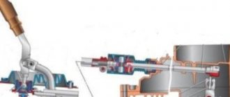
Gearbox device
General view of the gearbox
Before proceeding directly to the process of replacing the oil seal, it is necessary to consider the structure of one of the main elements of the car - the gearbox. So, what parts does the unit consist of:
Transmission device diagram
Gearbox: 1 – clutch release bearing; 2 – guide sleeve; 3 – input shaft; 4 – roller bearing of the secondary shaft; 5 – secondary shaft; 6 – retaining ring; 7 – satellite axis; 8 – speedometer drive drive gear; 9 – transport plug; 10 – wheel drive oil seal; 11 – tapered roller bearing of the differential; 12 – axle gear; 13 – satellite; 14 – differential box; 15 – clutch housing; 16 – driven gear of the main gear; 17 – drain plug; 18 – adjusting ring; 19 – driven gear of the 1st gear of the secondary shaft; 20 – synchronizer for 1st and 2nd gears; 21 – driven gear of the second gear of the secondary shaft; 22 – retaining ring; 23 – persistent half ring; 24 – driven gear of the third gear of the secondary shaft; 25 – synchronizer for 3rd and 4th gears; 26 – driven gear of the fourth gear of the secondary shaft; 27 – needle bearing of the secondary shaft gears; 28 – ball bearing of the secondary shaft; 29 – thrust plate; 30 – driven gear V of the secondary shaft transmission; 31 – 5th gear synchronizer assembly; 32 – nut; 33 – thrust washer; 34 – drive gear V of the input shaft; 35 – rear cover of the gearbox housing; 36 – ball bearing of the input shaft; 37 – gearbox housing; 38 – roller bearing of the input shaft; 39 – breather; 40 – input shaft oil seal