As you know, LPG can significantly reduce fuel costs, especially taking into account the constantly rising prices for petroleum products. Today, the most popular and widespread version is HBO 4. According to the rules, the installation of such equipment must be carried out in specialized service centers, which then issue the documents necessary for registering HBO with the State Traffic Inspectorate.
However, many car enthusiasts, for a number of reasons, are interested in how to install 4th generation LPG with their own hands. Also, especially taking into account the tightening of standards and fines for gas equipment without registration, drivers want to know how to remove the 4th generation gas equipment with their own hands, so as not to incur additional costs.
In some cases, owners of gas-powered cars also need to know what the principle of operation of a 4th generation LPG on an injector is, how to adjust a 4th generation LPG yourself, how to turn off the gas on a 4th generation LPG, etc. Next, we will look at the features of installing an LPG 4 on a car, what a gearbox for a 4th generation LPG is and the design of a 4th generation LPG gearbox, how the LPG 4 reducer is installed, and also how to set up such gas-cylinder equipment.
Benefits of using HBO
First, let's look at the advantages of installing fourth-generation gas equipment, and there are several of them, but they are important:
- Cost of gas (significantly less than gasoline);
- Consumption (in new generations of gas equipment, gas consumption is slightly higher than gasoline consumption);
- The gas contains no unnecessary impurities (which can be found in gasoline);
- Less deposition of combustion products inside the combustion chambers (affects the life of the power plant);
- When the car is fully refueled (with both gasoline and gas), the range will significantly increase.
With such a significant number of positive qualities, there is also a negative.
Disadvantages of using HBO
The first and noticeable disadvantage of the 4th generation HBO is the cost of the equipment; the higher the generation, the more expensive it is.
But even in this negative there is a positive quality of the equipment - it is universal, so by purchasing it, you can remove and install the equipment on different cars.
The second negative is the cost of installation, if you are sure that it will not be possible to install it yourself, as well as the quality of installation of the equipment.
And the third negative can be considered the advisability of using gas equipment in a car.
Since the equipment is not cheap, if the car is used rarely and for short trips, then installing an LPG will not pay off soon.
Features of HBO of different generations
So, it was decided to install HBO on the car. First you need to figure out which generation of equipment is best to use. It all depends on the car itself.
If a car uses a carburetor power system, then there is no particular choice - only 1st and 2nd generation gas equipment is installed on such cars.
Of course, there are craftsmen who install more modern equipment on such cars, but this is labor-intensive and expensive.
On injection cars you can install 2, 3 and 4 generations of gas equipment. Let's go through them.
HBO 2nd generation.
It is simpler in design, has mechanical control and adjustment.
This makes it possible to use it on many cars with both old and new injection power systems.
But this equipment has such a drawback as the lack of clarity in the dosage of gas supply, which often leads to its overconsumption.
HBO 3rd generation.
Already has a mechanism for precise dosing of gas supply. But the execution of the serve leaves much to be desired.
Equipment that is used as an alternative to the gasoline power system is significantly delayed in determining the amount of gas required at a certain moment in the operation of the power plant.
This drawback ensured a “short life” for equipment of this generation; it is now rare, and the feasibility of its use is a big question.
HBO 4 generations.
The most advanced equipment at the moment for use on modern injection cars.
And although gas equipment of the fifth and sixth generations already exists, at this time gas equipment of the fourth generation is the most popular and widespread.
Connected to the standard power system and using signals from the standard car power system control unit, the equipment performs a very precise dosage of the amount of gas required at a certain moment for optimal operation of the power plant.
Nuances of purchasing 4th generation HBO
Let’s focus specifically on the 4th generation gas installation, and we will consider the sequence of installing it on a modern injection engine.
The basis will be an ordinary modern injection car with 4 cylinders and average power, since installing this equipment on a car with a large number of cylinders, or with increased power indicators has its own characteristics.
This choice is due to the massive use of cars with exactly these indicators, regardless of the brand.
We decide on the choice.
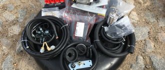
First you need to decide on the purchase of this equipment. All pieces of equipment can be purchased as a set, or individually. This has its positive qualities, as well as disadvantages.
Purchasing equipment as a set from a branded manufacturer will ensure high reliability of all elements, since they undergo quality certification.
And the installation of equipment will be easier, since the connecting elements and debugging of the equipment have already been completed. But purchasing the kit will cost much more.
By purchasing pieces of equipment separately, you can save a lot.
Many elements are common to all types of gas equipment, and their cost individually will be lower than in the kit.
But some elements of equipment are used only on installations of this generation. This includes a gas reducer, used only on the 4th generation of gas equipment, a gas train with electromagnetic injectors, an electronic control unit, and the sensors required for the operation of this equipment - gas temperature and pressure.
You need to purchase this equipment with a serious approach; it is better to overpay a little for high-quality equipment than to be disappointed in the future by the unreliability of its operation.
Having all the elements in hand, either as a kit or as an assembly, you can begin installation.
Of course, you can leave all this work to specialists, but you will have to pay. Or you can do everything yourself, which is cheaper and will give you the opportunity to fully understand how the equipment works.
Possible faults
Summarizing the story about the design of LPG injectors, it would not be amiss to pay attention to their possible malfunctions. In fact, there are few of the latter, or rather only three:
- The first option is that the injectors or individual ones have failed. The problem is solved by disassembling, cleaning and, if possible, repairing faulty elements. If this approach does not produce an effect, then you will have to install new nozzles;
- The second option is that there was a malfunction in the injector-control unit system. The malfunction can be eliminated by “dialing” the network and setting up the equipment “newly”. Often, a problem of this nature is solved by contacting an HBO specialist;
- The third option is that the injectors are simply clogged. The easiest way to get rid of this “breakage” is to simply remove the dispensers, disassemble them and clean them thoroughly.
Note that on older generations of gas equipment (up to 3), problems may occur with confrontation between the car’s mono power systems and gas equipment. It seems possible to solve them by introducing an injector emulator into the LPG system (the most preferable copy is from BRC). On most third and all subsequent HBOs, the conflict between mono power systems and equipment is resolved automatically in the control unit, so a similar equipment failure cannot happen with them.
Any malfunction of the injectors is indirectly manifested by the following symptoms:
- instability of the motor;
- loss in power and dynamics;
- inability to switch to gasoline;
- increased fuel consumption;
- failures in engine operation when driving.
Regardless of the nature of the problem with the injectors, they should be eliminated immediately, because using faulty equipment is quite dangerous. Especially when it comes to HBO.
In general, the most important provisions on the issue being considered today have been successfully addressed. We hope the material presented above was useful to you. Good luck on the roads!
Installation of cylinder, filling device, lines
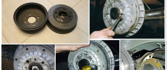
Let's start with something simple - installing elements common to all gas equipment. Let's start with the balloon. Its installation location depends on the design features of the car.
If the car has a sedan body and there is a trunk of significant volume, then it is more advisable to use a cylindrical cylinder. Its capacity is greater; it is usually attached to the rear wall of the trunk.
If the car is a hatchback, it does not have much luggage compartment, so it is more advisable to install a toroidal cylinder in the place reserved for the spare wheel, if, of course, there is one.
The cylinder must be securely fastened. For this purpose, tapes with fasteners at the ends are used. It is desirable that these tapes have a rubberized surface.
To properly fasten the cylinder, you need to take measurements of where you will need to make holes in the body.
You will also need to mark the places where the high pressure line will exit from the cylinder. After which you will need to make holes in the body in the marked places.
After this, the holes will need to be treated with anti-corrosion treatment.
To further prevent damage to the line from the sharp edge of the hole, you can insert pieces of plastic pipe into it, through which you can then pass the line.
Although the toroidal cylinder fits into the seat of the spare wheel, it also needs to be secured to prevent it from moving.
Fastening is also done with tapes with preliminary preparation of the exit site for the highways.
In both cases of installing the cylinder, they should be installed so that the multivalve installed on it is located in the upper part of the cylinder, and there is easy access to the gas shut-off valve.
Next you need to install the filling device. The choice of its installation is extensive; it is only important to take into account that this place should not become heavily polluted during the operation of the car.
The device can be installed on the rear fender, in the body of the bumper, or under the bumper.
The main thing is to ensure that the line from the device to the cylinder is laid where it will not interfere and there will be no possibility of damaging it.
Let's move on to the highways.
The line consists of brass tubes that must run under the car and go into the engine compartment.
To prevent damage to the lines, it is better to attach them to gasoline pipelines, because they are installed where there is no possibility of their breakdown.
How to install a gas cylinder
When installing gas equipment on your own, two types of cylinders are used:
HBO equipment
- cylindrical cylinders;
- toroidal cylinders.
Cylindrical cylinders have an oblong shape. To protect against gas leakage, they are equipped with a shut-off valve. Used in cars with a spacious trunk and on trucks.
Toroidal cylinders have a “tablet” shape. Used in cars with a small trunk.
The cylinder is mounted in the free space of the body. To protect against displacement, they are secured with steel strips. The ends of the strips are connected with bolts.
After mounting and securing the cylinder, the end of the filling valve is brought out. The end of the hose with a fitting is secured under the rear bumper or under the rear fender.
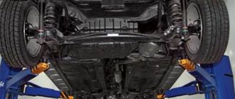
Features of gearbox installation
After running the lines into the engine compartment, they need to be routed along the left side to the gearbox installation site.
The gearbox must be properly secured to the car so that there are no problems in the future.
It is attached only to the load-bearing part of the car, that is, to the body or subframe. It is prohibited to install it on the engine. It is important that there is good access to it.
The gearbox is then connected to the cooling system of the power plant. To do this, it is inserted into the cooling system pipes through tees.
It is important that its insertion is parallel, that is, the flow of coolant into the gearbox should be made from one pipe, and its outlet through another, and not the same one.
Next, a vacuum pipe is connected to the gearbox. Vacuum is taken from the intake manifold.
A fitting cuts into it, and it is connected to the gearbox by a pipeline. If there is no fitting, you can wait to insert it for now.
After this, you can connect the high pressure line to the reducer. Only before this, a filter is included in the design to capture mechanical impurities - a “coarse” filter.
How to install a mixer and gasoline valve
The mixer is mounted between the carburetor and the manifold. The joints are sealed with rubber gaskets or silicone sealant. Careful sealing of joints protects cylinder equipment from air entering the system.
Gasoline valve for HBO
The gasoline electric valve is installed from the side where the fuel pipeline connects to the gasoline pump.
Attention! The gasoline electric valve is installed after the gasoline pump. Otherwise, the fuel pump will not be able to supply fuel to the carburetor.
To install the valve, the necessary part of the pipe is cut in the area between the fuel pump and the carburetor. A valve is inserted into the resulting incision. The joints are sealed and clamped with clamps.
Then proceed with the installation of the gas valve. It is installed on the opposite side of the gasoline electric valve. The outlet of the fuel line is connected to the gas valve.
Gas train
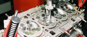
Leaving the gearbox for now, we move on to the intake manifold. It will be necessary to insert gas fittings into it.
Since you will have to drill holes in the manifold, in order to prevent chips from getting into the valve mechanism, it is better to insert the fittings on the removed manifold.
You can, of course, make holes on the manifold mounted on the engine, but then you need to drill carefully to minimize the entry of chips.
We will assume that the manifold has been removed and can be drilled.
The holes for the gas supply fittings should be made as close as possible to the gasoline injectors, but at the same time take into account the position of these injectors so that they do not interfere with the installation of gas supply pipelines in the future.
Below are several options.
At the same time, a hole is drilled for the vacuum supply fitting to the gearbox.
The holes must be smaller in size than the diameter of the fittings. Then you need to cut threads in the holes.
Before screwing in the fittings, their threads must be lubricated with sealant.
After this, the collector is installed in place and further installation of equipment continues.
Next in the connection diagram is the installation of a ramp with electromagnetic injectors.
The ramp is installed at the top of the collector, but so that it does not interfere with pipelines and wiring.
Pipelines are laid from the ramp to the installed gas supply fittings. It is important to ensure that the length of the pipelines running from the ramp to the fittings must be the same, otherwise there will be a malfunction of the system.
Having installed the ramp, you need to lay a gas supply pipeline from the reducer to it. At the same time, another filter is inserted into the pipeline - fine gas purification.
Again, we return to the gearbox and connect the vacuum supply pipeline to it. All pipelines must be covered with clamps to prevent gas leakage at the joints.
This completes the technical part of the installation of gas equipment, let's move on to connecting the electronic part.
Self-installation of gas equipment
Second-generation equipment has become most widespread. It is characterized by simplicity of design and installation. Distinctive advantages allow you to install LPG on a car yourself.
Connection diagram for gas equipment
System installation work is carried out in the following order:
- Installation of the cylinder.
- Installation of shut-off valves.
- Fastening of mixers and valves.
- Installation of dispenser and gearbox.
- Fixing the control panel.
- Checking the tightness and operation of the system.
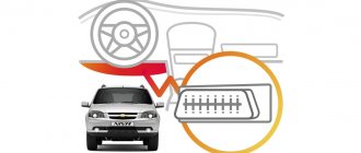
Installation of the HBO control unit
The operation of the equipment is controlled by an electronic control unit, which comes with the 4th generation gas equipment.
Wiring to the control unit.
First you need to decide on the location of the block. Access to it should be free, but at the same time it is necessary to minimize the length of the wiring so that after connecting it, a heap of tangled wires does not form under the hood.
All wiring coming from the controller is divided into several parts, each of which performs its own functions.
The main thing is to have on hand a diagram with a color definition of which part this or that wire belongs to. Or at least this one.
Before connecting the wiring, you need to disconnect the on-board network from the battery.
First, you need to determine which wires are responsible for powering the unit. There should be three of them - to the positive terminal, to ground, and to the positive terminal of the ignition switch. Having separated them, it is better to immediately connect.
Wiring to injectors.
Next, we move on to the wiring responsible for the operation of the injectors - the fuel part. This wiring is connected to the wires going to the gasoline injectors.
After determining which wires are connected to each specific injector, they are inserted.
The color scheme determines which wire needs to be connected to which one, then the connection is made.
You can use conventional twisting followed by insulation, but such a connection is not reliable; it is still better to solder the wires from the control unit at the connection points and then insulate them.
For the fuel part of the wiring, all that remains is to connect the connectors back to the gasoline injectors, and also connect the connectors of the electromagnetic gas injectors.
The fuel part of the wiring is finished, let's move on to the next one.
Signal wiring.
Let's move on to connecting the next part of the wiring - the signal one.
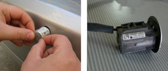
This wiring is designed to transmit signals from sensors that come with the equipment - gas temperature and pressure.
The accompanying instructions indicate in which places the sensors should be placed. After installing the sensors, wiring from the control unit is connected to them.
Wiring for the operating mode switching unit.
The last part is the control of the operation of the control unit, that is, the unit for switching the operation of gas equipment.
The control unit is installed in the cabin, in a place accessible for viewing and control.
After which it is wired and connected.
It is advisable to collect all wires into bundles and secure them to prevent the possibility of accidental damage.
The control unit has one more output for connecting a computer, which regulates the operation of the equipment.
This outlet must be freely accessible to facilitate adjustment and diagnostic work.
At this point, the work on installing 4th generation gas equipment on the car is completed.
But what remains is checking the tightness of the system, and then checking and adjusting the operation of the equipment.
Related articles:
— Selection of HBO injectors. This article will help you make a decision when choosing gas injectors.
We install HBO 4 according to the instructions and photo report.
Rules for installing 4th generation HBO.
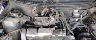
Good afternoon . I'll start with the simplest thing - OPEN THE HOOD. We look at the engine and determine the future position of the GEARBOX. Since it is far from a small detail, we need to provide and measure the space under the hood for its convenient location.
We take several things into account when installing the GEARBOX:
1
The place where the gearbox with connected hoses should be located should be easily accessible for removing and servicing the gearbox, or rather replacing filters.
2
Position the gearbox as far away as possible or taking into account engine vibration, that is, the gearbox mount should ALWAYS be located on the main frame of the car NOT ON THE ENGINE!!!
3
Consider the location for connecting the antifreeze hoses, taking into account the bends of the hoses. It is important that the hoses are not twisted or kinked during installation. That is, to ensure unhindered circulation of the antifreeze passing through the hose to the gearbox through the system.
4
Consider the location for the main gas supply via a copper or plastic pipe. This procedure is also important for taking into account tube kinks during operation of the machine and subsequent dismantling of the gearbox in the future.
Having chosen a convenient place, you can attach the gearbox to the selected location.
The next step is CONNECTING THE ANTIFICE HOSES.
WE CONSIDER
several things when installing antifreeze hoses:
1
ALWAYS connect the antifreeze hoses IN PARALLEL TO THE SYSTEM!!!!
Example:
There is an ENTRANCE for the supply of antifreeze to the heater radiator and an OUTPUT for the return of antifreeze from the heater radiator. They are not always conveniently located for insertion into the system, but it is important to connect to them. In rare cases, craftsmen use other connection points, but this requires them to know where to get the antifreeze SUPPLY and where to connect the RETURN correctly. If you are not sure where the supply and return are, then it is better not to tempt fate. If it is connected incorrectly or inserted into the cooling system, the antifreeze will not sufficiently warm up the gearbox or the antifreeze will stagnate. Which means no circulation.
IMPORTANT:
When connecting the hoses into the cooling system to the stove!!! Consider the presence of a SHUT-OFF VALVE. Sometimes in cars there is a valve first, then the hose is connected to the supply to the heater radiator. The connection must be made up to the shut-off valve. By cutting in a tee.
2
Use only connections through a tee and not through a 90″ angle. Connecting through a tee is considered a parallel connection, which means an equal supply of hot antifreeze to both the gearbox and the heater radiator. This is necessary so that both the interior of the car and the gearbox itself receive an equal portion of heat in temperature. This way you are warmed up and the reducer operates in the required gas heating mode.
IMPORTANT:
If you connect it, for example, through a serial connection, then the last part will always receive already cooled antifreeze and thus something will produce low efficiency. If you first supply antifreeze to the stove and connect the stove output to the gearbox supply and cut the second remaining return hose of the gearbox into the return line to the engine, you will get the effect of weakly warming up the gearbox when the stove is running. That is, in the summer we will not complain about the gas system not working correctly. But in winter, when the stove (fan) is on, we will immediately notice the strange operation of the LPG system. Let's look at what's happening. When hot antifreeze got into the heater radiator, the heat blown into our cabin by the fan was released into the external environment. Thus, some of the heat from the antifreeze was given to us to heat the interior. Having passed through the radiator of the stove, the antifreeze, which has already cooled down from 85″, turns to reach the gearbox at 50″ and this heat is critically insufficient to warm up the LPG gearbox. Temperature sensors of the reducer send a signal to the LPG computer, thereby turning off the system due to insufficient heating of the gas. I think we sorted this out and moved on.
Now we begin to prepare the place for the cylinder.
It's a little easier here. If we have selected a cylinder for a spare tire, then by placing the cylinder in place of the spare tire, you need to select its correct location for connecting the SUPPLY and REFUEL pipes.
We take into account
the following: Important:
1
It is important to look and try to see where the tubes will pass under the cylinder. The hot muffler should not interfere and there should be no moving body parts subject to vibration near the pipes located.
2
Having determined its position, we attach the cylinder to the body with bolts (2 pieces) and drill a hole in the bottom under the hole in the cylinder. The holes should be located symmetrically to each other. That is, looking at the cylinder from the top you should see a hole in the body.
3
After drilling, paint the hole with spray paint and insert a plastic safety fitting. In order to avoid rubbing the tube on the sharp edge of the hole in the body.
4
We install the multivalve into the cylinder. Having previously lubricated the seating area of the valve and cylinder with lithol and salidol.
5
We lay the gas CHILLING tube from the multivalve to the place where you will place the CHILLING VALVE. I will not describe the installation of the filling valve, I will only say that it must be firmly attached to the body, taking into account the connection of the copper pipe.
6
We connect the tube to the connectors of the multivalve and the refiller JUST A LITTLE TIGHTENING THE NUTS. Later we will tighten them completely, but only after we have done this will we lay the gas supply pipe to the reducer itself.
7
We proceed to laying and fastening the gas supply tube from the valve to the reducer. We take into account the following: it is better to run the copper tube from the side of the hood from the gearbox location. Since it is not flexible and you need to avoid creases. When running the pipe to the bottom, it is preferable to lay it with the petrol system pipes. This makes it easier to attach it and you can immediately see where you need to run the tube under any part. We make all bends of the tube smooth and not sharp so as not to break the tube. We take into account the moving parts of the suspension and so on. We finish the end of the tube by first insulating its end with electrical tape. Protecting against debris getting inside. We release the end near the multi-valve with a small allowance. We will always have time to cut off the excess. We begin to secure the tube itself with ties. Once secured, we go under the hood and see how to route the pipe, taking into account the bypass of moving parts. Having tried out how the tube will fit to the gearbox, we cut it 40 cm longer than the location of the gearbox itself. This is necessary in order to make a supply of tube by rolling it into a ring with a diameter of 12 cm (in a ball). In this way, we will protect ourselves from tube kinks when dismantling the gearbox in the future and take unexpected cases into account. We connect the tube to the reducer and the return end to the multivalve.
IMPORTANT:
The place where the tube is connected to the multivalve will be terribly inconvenient if you have no experience.
Therefore, my advice, since you don’t bend such tubes very often, try to practice on a 1m piece when you want to connect to the multivalve fitting or reducer valve. This way you will avoid incidents of FRACTURING a tube in an already laid line. It is very important to do this CAREFULLY, because if the tube is bent and fractured, it will have to be replaced!!!!!!!!!!!!!!!!!!! Under no circumstances should you bend back hoping that nothing bad happened. YOUR LIFE AND THE PEOPLE AROUND YOU DEPEND ON THIS.
And so now, having baited all the ends of the tubes, we begin to tighten them, BUT!!! Do not forget to 1 put on the nut 2 barrel (barrel) Having done this, we have finished installing the cylinder.
The cylinder is standing, the reducer is installed, the antifreeze tubes are connected, the gas filling and supply lines are closed.
Installation of gas injectors.
Consists of several stages
1
Correctly supply gas to the manifold. Make inserts.
We take into account
following:
Make the insert as close as possible to the gasoline injector, taking into account the direction to the location (CORNER) of the gasoline injector itself. This point is very important because the closer the mixture is to the candle, the more stable and correct the mixture burns. We drill holes with a 5″ drill, take a tap with a diameter of 6″, lubricate it with oil and cut the thread. You should not be afraid of chips getting into the collector, but it is advisable to avoid getting as little as possible. Then we take the fittings of the taps and lubricate them with liquid to secure the threads.
IMPORTANT!!!
When drilling holes for inserts, take into account the space for the hose since the hose wall also has a thickness of about 4 mm. To make it convenient to put on and remove the hose from the fittings!!!!!!!!!! The brass inserts are therefore quite fragile and are made with a cone. When screwing in, you need to tighten it correctly without over-tightening. If you overtighten it may break off and the thread will remain in the manifold!!!!!! Carefully and effortlessly. Screw in confidently, keeping an eye on the thread; as soon as the conical part reaches the manifold, the insertion will become tight - IT IS IMPORTANT NOT TO OVERDO IT HERE.
2
We install the injectors. We take into account that all hoses from nozzles to fittings should not be longer than 18 cm and should be the same in length!!! Having chosen a place, we firmly fasten and connect the hoses. I use connection hoses with a diameter of 4 mm, but many people use 5 mm. It's your decision what diameter to use. If the hose does not fit tightly around the fittings, use clamps. This will happen for sure.
We're done with the injectors.
Electrical part.
Here many begin to throw up their hands or, better yet, simply lose the desire to do something themselves. Don't be scared by the NUMBER OF WIRES)))))))))))))))))))))) At first glance, many simply faint without having any experience in electrics, but it's not as scary as it might seem. Almost all HBO systems are the same in wire colors. And any reputable HBO system includes instructions for connecting in a drawing and color designation. Therefore, if you look carefully at the instructions, everything is described in black and white. And I, in turn, will try to tell and explain in detail and clearly!!!!!
IMPORTANT:
Cover the front fenders of the car with protective covers, but if not, at least cover them with blankets. This will save you from scratches from wires on your car.
1
Selecting the location of the LPG unit itself.
2
Remove the + terminal from the battery and place the car keys next to you. This is necessary so that when we finish putting on the terminals, the alarm does not accidentally close the car. I speak from experience. ))))))))))))
WE CONSIDER:
Length of wires from the unit to the gearbox. Most often this is the maximum length point that we need. Having approximately laid the power supply wire to the valve coil around the body, we see if there is enough of it (BLUE AND BLACK WIRE COLOR) in the harness there is only one. Check color instructions. And you will make sure that these are the wires that go to the valve coil.
2
If everything is fine, we attach the block (brains) rigidly to the body, taking into account the avoidance of moisture on the block and overheating from third-party engine parts. Do not forget about the possible dismantling of the unit and that there would be access to other parts of the car.
3
We arrange the power cable to the battery (RED WITH FUSE AND BLACK) Connect red to + black to - (first pull out the fuse and put it in your pocket)
4
Distribute the wires into bundles.
Something will go to the engine, some part to the gearbox, some part to the interior. As soon as we start distributing the wires into bundles, the picture will begin to emerge into a pleasant procedure where many things will become clear and easy. Don't forget we have an assistant in the form of instructions in color. 5
Bunches look something like this
Engine:
The wires going to the gasoline injectors - have their own colors, look at the instructions (possibly: 1 green - 2 yellow - 3 red - 4 blue) The wires going to the gas injectors - have their own colors, look at the instructions (possibly: 1 green - 2 yellow - 3 red - 4 blue) PRM wire (signal from the coil - engine speed) - most often it is BROWN Control power wire (+) - color RED
IMPORTANT :
When you arrange a bundle of wires for the ENGINE, take into account vibration and mobility.
Let's say we do it this way, the reserve is in the form of a loop, allowing the wires to move freely when the engine is running.
This is necessary to account for breaks due to wire tension.
Gearbox:
Wires going to the gearbox coil color BLUE and BLACK Wires going to the gas level color WHITE and BLACK Wires going to the gearbox temperature sensor ORANGE AND WHITE
IMPORTANT :
I lay these wires along the partition between the engine and the wipers.
Salon
:
This harness is the thickest and has at least 5 wires of different colors, there is no point in describing them since they are definitely different for everyone!! But it’s hard to confuse it with something because it stands out from the background of all the others in terms of thickness and the number of wires. Here the instructions will help us.
Body:
Wire going to the lambda probe color - PURPLE Wire with connector for MAP sensor (what is a MAP sensor, see the instructions)
6
The bundles are made and we begin to connect.
ENGINE HARNESS:
We connect the wires that go to the gasoline injectors into the circuit of the injectors themselves. To do this, remove the connectors from the gasoline injectors, carefully place the terminals on the battery, turn on the ignition and ring the injector chips. You need to find + on all of them and remember their location. The adjacent wire on the chip is the wire that we need!!!! Let me clarify on the chip there is a constant plus and an impulse minus. So we need an impulse minus. Turn off the ignition and cut the pulse negative wires on all injectors. From him (them) we will take a signal to the GAS BLOCK. Looking at the instructions, we see that in the wiring harness for the injectors there is a wire of the same color and with a stripe
EXAMPLE:
4 cylinders machine, respectively 4 wiring harnesses for your injectors, each with two wires. YELLOW AND YELLOW WITH BLACK STRIPES GREEN AND GREEN WITH BLACK STRIPES RED AND RED WITH BLACK STRIPES BLUE AND BLUE WITH BLACK STRIPES The wire that is cut on the injector chip now has two ends 1 the one that is attached to the chip 2 the one that goes to the car computer, that is into the common injector harness.
Take the wire from the gas
system, monochromatic yellow, connect to the wire going to the connector of the gasoline injector 1. Take the wire from the
gas
system, yellow with a stripe, connect to the wire going to the wire going to the injector harness 2 (that is, to the car’s computer). We do the same with the rest of the gas wires, connecting to the cut wires on connector for petrol injectors.
IMPORTANT: There is a RULE here, it is very important to follow it!!!! We look at the injectors themselves, they are in a row, for example from left to right 1-2-3-4 This means that the wires we cut on the connectors are in strict sequence. 1 connector we connect gas wires yellow 2 wires green 3 wires red 4 wires blue
Since I already mentioned that the systems are different, the color of the wires may not match those described by me. But the instructions in color will always help us, where the connection sequence is written and which color corresponds to which cylinder (injector, that is, our connector). It is important to remember which color you connected to which cylinder (injector connector). After you are done with the connectors, isolate them and put the connectors back on the gasoline injectors. Let's move on to the wires that connect directly to the gas injectors.
These wires already have their own connectors, they are numbered, look carefully. If there is no numbering, then look at the wires and see that on the connectors they correspond to the colors of the wires that we did when connecting to the connectors on the gasoline injectors.
That is, the colors are the same and the sequence is the same: 1 connector yellow wire 2 connector green wire 3 connector red wire 4 connector blue wire
And now the most important thing!!!!!!!!!!!!!!!!
We connect the connectors as we were previously connected to gasoline connectors.
So that you don’t get confused by the long description, I’m writing a connection table. Remember, we connected from left to right.
| 1 cylinder |
| connector 1 force benz yellow |
| connector 1 gas force yellow connect to gas injector 1 connector (from left to right) |
| 2cylinder |
| connector 2 force benz green |
| connector 2 gas force green connect to gas injector 2 (connect from left to right) |
| 3 cylinder |
| connector 3 force benz red |
| connector 3 gas force red connect to gas injector 3 (connect from left to right) |
| 4 cylinder |
| connector 4 force benz blue |
| connector 4 gas force blue connect to gas injector 4 (connect from left to right) |
Now we check how our gas hoses are connected from the injectors to the inserts in the manifold. From left to right 1 gas injector yellow color of the wire on the connector is connected by a hose to the 1st cylinder 2 gas injector green color of the wire on the connector is connected by a hose to the 2nd cylinder 3 gas injector red color of the wire on the connector is connected by a hose to the 3rd third cylinder 4 gas injector blue the color of the wire on the connector is connected by a hose to the 4th cylinder
If everything is fine, we move on.
PRM revolutions
This is the brown wire that should connect to the impulse wire to the coil. This is necessary in order to read the engine speed correctly. It's not difficult to find. Turn on the ignition, go under the hood and find the connector that goes to connect the ignition coil itself. Let's call. There are often three wires, one is +, the second is -, and the third we need is (minus) pulse. In order not to go into long descriptions of how and what the poking method will help us with)))) of all the wires that we have, we immediately discard + we don’t need it, there will be two wires left - minuses and one of them is exactly what we are looking for. We connect to one of them without breaking the wire, but simply remove the braid and add our BROWN wire. Let's isolate.
Managed Plus +
RED
We must connect its color to the place where power is supplied (appears) when the ignition is turned on. Often it is connected either from the positive supplied to the coil, which I do not recommend doing. And take it from the wire + on the connector of the gasoline injectors themselves. Remember, I wrote that the injector has a constant plus and a pulse-controlling minus. This is where we will connect our red control plus wire.
And so what kind of picture did we get regarding the electrical part? We connected the injectors, crashed into the gasoline system and connected the revolutions with the control plus.
Wiring harness GEARBOX
:
Everything here is terribly simple. Blue
We connect the wire paired with the black one to the terminals on the gearbox coil - polarity does not matter.
Orange
paired with white are connected to the temperature sensor on the gearbox.
We take the temperature sensor, screw it into the gearbox and connect it by color. Let's isolate. the white
wire paired with a black one responsible for the gas level (the gas level sensor is installed on the multivalve and the wire is pulled together with a copper tube in pairs) to the wire coming from the sensor on the multivalve.
Harness SALON
These are the wires of the control button (on/off the HBO system). This is the thickest wire with a large number of wires. In the driver's cabin we are looking for a place where there will be a button and stretch a wire from the engine compartment into the passenger compartment. And we connect all the wires by color (they are the same on the button and in the harness) color to color. We arrange the wire and attach the button.
Harness BODY
Purple
instructions describe how this (THESE) wire is connected. Often it is simply cut off at the root and isolated. I won’t describe why, but it’s not critical. If you don't connect it. If you are not sure that you will connect it yourself, do not connect it.
IDA
The sensor wire is always with the connector, you won’t confuse it or see the instructions. it needs to be connected at the very last moment since the thing is delicate and fragile.
INSTALLATION OF MAR SENSOR
There are 2 types of MAP sensors. Type 1 - separately mounted on the body in the driest and most ventilated place. Type 2 - mortise into the gas supply hose from the reducer to the injectors.
We look at what type and install it in accordance with the type. The MAP sensor has several outputs on the body (MORTASED TYPE)
There are two wide outlets connected to the gap in the hose running from the reducer to the gas injectors, diameter 12mm. The scheme is as follows - reducer - fine gas filter (follow the direction of the arrow on the filter from the reducer towards the injectors) - mar sensor - injectors.
And two thin outputs for connecting vacuum tubes. The connection diagram is in the instructions - gearbox (the gearbox has the same outlet for the hose) - mar sensor - insert in the manifold for vacuum - second output on the mar sensor
I didn’t write before that you need to drill a hole in the intake manifold for the MAP sensor because I didn’t want to confuse you. But now the time has come. The procedure is simple and is carried out in the same way as with taps into the manifold for supplying gas from gas injectors. Only with a small amendment. IMPORTANT:
Choose the right place for the insertion so as not to mix the separate chambers for gas supply and the common manifold flask. Let's look at the structure of what our collector looks like; the principle is the same for everyone except for the shape itself. There is a common flask that is gradually divided into sections for our cylinders. The separation is clearly visible when we look at gasoline injectors. Each nozzle has its own division. We need to cut into these divisions along the cylinders, that is, into a common flask somewhere at the extreme point.
Let's look at the example in the photo of white hoses (you need two inserts):
With the sidebar we figured out the vacuum, I described what to do. I also described how to connect the gas supply connection hose. Tighten everything with clamps. Lay the wires and tie them together. We connect the MAP sensor wire to the sensor itself. We check whether everything is connected correctly as described by me. If necessary, add antifreeze to the maximum and make sure that there is no air lock in the system.
IMPORTANT!!!!
I specifically did not describe what to do with the screws on the injectors themselves since I have no idea what you will buy. Since the nozzles must be specially drilled for your machine power, NOZZLE DIAMETERS. This procedure should be done by an experienced professional, not you. There is a good chance that you will make a mistake when doing it according to the description. And further configuration of the machine on the computer also depends on this. With all due respect, I don’t dare describe this procedure to you because it takes a long time to learn. BUT THERE IS A WAY OUT!!!
Setting up HBO 4th generation instructions
1 You can use my services CLICK HERE
, I’ll teach you. 2 You can use the services of other masters. 3 Take the risk yourself, but here you need to buy a cord, it costs $30-45. Install the program and learn to understand many of the subtleties. I do not advise !
And now the final stage.
How to start the car correctly after work has been done. There is a delicate nuance here. We sketch out the terminals (check where the keys are)!!! We get into the car and turn on the ignition but don’t start it. So we repeat the procedure three times so that the fuel pump pumps up the pressure into the ramp sufficiently. Now let's remember. If you don’t catch the moment at the first flash, the car may not want to start for a long time after that. It may scare you that you have broken something, but it doesn’t matter, everything is fine, chips just got under the valve and there is no normal compression. To avoid this, try to catch the moment of the first flash when pressing the pedal. This is necessary so that the excess in the combustion chamber quickly burns out - chips. Without damaging the valve seats. And so good luck. If you have done everything correctly and installed the LPG, the machine is ready for SETUP and the correct selection of injector nozzles. We feel the gearbox with our hands; it should be hot; if not, try using a gasket to remove the air plug.
The material is written to familiarize you with the procedure for installing GAS and installing gas cylinder equipment.
The author is not responsible if what is read (described) above becomes a reason for accusations of an incorrect explanation of how to install gas on a car. The instructions are not complete due to the installation of HBO by incompetent persons. The system will not work without the final work of appropriately qualified craftsmen.
Checking the tightness of the system
So, the equipment is installed, you need to check the tightness of the system.
To do this, you need to go to a gas station and “blow out” the full tank. But at the same time, the gas supply valve to the system must be closed.
Then he goes to the viewing hole.
All connections and pipelines of gas equipment up to the gas train must be moistened with a soap solution before opening the supply. If gas passes through, this solution will bubble at the leak site.
The leak test can be done in parts. First, moisten the pipes coming from the cylinder with the solution.
Not only the connections are checked, but also the pipelines themselves, since a leak can occur due to a defect in the pipeline itself or in the event of a breakdown during installation.
After checking the lines going into the engine compartment, you need to check the tightness of the connections of the equipment installed there.
The gas supply to the reducer and the outlet from it to the gas train are checked. There is no need to check further until the equipment is connected to operation.
Connections downstream of the gas train can be checked later.
If the tightness test shows that there is no gas passage, you can proceed to the next step. If a leak is detected, for example, at the junction of pipelines with equipment, then the gas supply is shut off and additional crimping or repacking of the connection is performed. After which a re-check is carried out.
If a leak is found in the pipeline itself, it must be replaced from connection to connection.
Attempting to seal a leak with improvised means practically does not lead to positive results.
After replacing the damaged pipeline, a leak test is carried out again. It is important to ensure that there are no gas leaks anywhere.
Gas pipeline wiring
Gas pipeline wiring - what it looks like
After installing the cylinder, a gas pipeline is installed from the tank to the engine compartment. For safety reasons, the pipeline is laid outside the car.
The diameter of the hole in the container is taken to be 1-2 mm larger than the diameter of the pipe. The difference in diameter is compensated by inserting a piece of plastic pipe. The resulting gap serves for additional ventilation of the multivalve. The edges of the hole are treated with anti-corrosion mastic.
The gas pipeline wiring is placed in the niche of the fuel line. The pipe is fixed in a constant position using steel clamps. After installing the pipe, begin installing the mixer and valve.
Connecting HBO to PC
Both the cord and the diagnostic program can be purchased. Typically, equipment manufacturers sell them.
After installing the software on the laptop, it is connected to the control unit.
In order for their connection to occur, the control unit must be powered, that is, the ignition switch must be turned on, but the engine must not be started.
If the connection does not occur, the laptop may have an outdated version of software installed, but you also need to check the tightness of the contacts.
If the connection is successful and the program is launched, all the basic information on the engine will be displayed on the laptop monitor - the number of cylinders, types of installed injectors, their polarity, engine speed, current temperature, pressure in the system.
In this case, the system control unit installed in the cabin should light up with warning lights.
One is green, indicating the use of gasoline as fuel, and will glow constantly, the second, red, will flash, signaling the possibility of connecting gas equipment to operation.
In the future, if the equipment is properly configured, signals will be sent to this unit in accordance with certain operating modes.
Basic parameters of injectors
The development of gas cylinder equipment has provoked the emergence of a huge number of varieties of nozzles. The parameters for the division of dispensers are not several positions, but about ten of the most important divisions. To be more precise, HBO injectors are classified according to:
- Case material (metal or plastic);
- Type of fuel being dosed (propane-butane or methane);
- Coil operating voltage;
- Working pressure and maximum possible;
- Opening and closing times (that is, they can be instantaneous, delayed or customized);
- Electrical resistance of the coil;
- Operating temperature range;
- The outer diameter of the outlet fitting;
- Valve seat diameter;
- Jets available for calibration.
In fact, most of the characteristics of LPG injectors are not required by the average car enthusiast when selecting them. However, for experienced motorists or mechanical aces, each parameter can be extremely important, because the totality of them largely determines the nature of the functioning of a gas engine.
Auto-configuration of equipment
In this case, you need to press the button for forced operation on gasoline. After this, the red warning light will go out.
To configure the operation of gas equipment, the power plant must be warmed up on gasoline.
After starting the engine, the correct compatibility of the program with the control unit can be checked again by comparing the indicators of the on-board computer with the indicators on the laptop screen, since information about the operation of the engine is displayed there.
After the engine reaches the optimal operating temperature, you can begin auto-calibrating the operation of gas equipment.
This is done by clicking on the window that says “auto-tuning” on the laptop screen.
The essence of this setting comes down to the following. After turning on auto-calibration, the electronic control unit checks the main parameters of the engine - operating temperature, pressure, etc., and, if they correspond to the required parameters for calibration, begins to connect one of the gas injectors to operation.
To do this, he turns off the working injector and connects the gas one; he usually starts doing this from the first cylinder; the connection of the gas injector can be monitored on the laptop monitor.
But when connected, the control unit supplies minimal fuel, which leads to engine vibration, since the control unit has not yet adjusted to the operation of the standard control unit.
Next, the control unit begins to receive information from the standard unit and process it, that is, adapt to its operation; as a result, it adjusts the amount of gas, which is equivalent in energy output to the amount of gasoline. With the correct amount selected, the vibration of the power plant will subside.
Next, the control unit performs the same operation, but with a different nozzle.
Moreover, the control unit for calibration uses the non-sequence of the arrangement of the cylinders, but the order of their operation. If, for example, the operating order is 1-3-2-4, then he will calibrate the injector of the third cylinder next.
Since the sequence of actions of the control unit is identical to the first cylinder, when the gas injector of the third cylinder is connected to operation, the vibration of the power plant will appear again, but it will be weaker.
Next, when calibrating the remaining injectors, you can determine whether the gas equipment was connected completely correctly.
The fact is that after connecting the second gas injector to operation, if installed correctly, the activation of the remaining injectors will not manifest itself in the form of vibration of the power unit, since the supply of gas to two injectors and one gasoline during calibration is sufficient for the engine to operate without vibration.
If vibration persists even after calibrating the second injector, this is a signal that the correct gas supply to one of the electromagnetic injectors has been disrupted.
Problems with operation can be caused either by the difference in the length of the pipes from the ramp to the fittings or by a leaky fitting of the fitting.
The program installed on the laptop will indicate on which cylinder the malfunction occurred. If this malfunction occurs, it must be corrected. Next, auto-calibration is performed again.
Setting up HBO yourself
Let us immediately note that if installing an LPG taking into account the instructions is a complex but feasible task, setting up an LPG assumes that there is a clear understanding of why this or that action is being performed. In other words, for example, setting up a 4th generation Digitronic HBO with your own hands or setting up any other system can rightfully be considered a complex and responsible task.
It is important to understand that errors in settings can lead to unstable operation of the internal combustion engine, various failures, and even failure of the power plant and individual vehicle systems. Please note that if you are not confident in your abilities, it is better to immediately entrust this procedure to an experienced master. If you want to configure the HBO yourself, you will need to buy a special wire (cable) and also install the appropriate software on your laptop.
Please note that the information below is general, that is, it allows you to configure the gas system “on average” so that the engine runs on gas, without the risk of breaking the internal combustion engine or reducing its service life. However, only a specialist can make fine adjustments, which reduces consumption in different modes, increases engine performance on gas, etc.
We also recommend reading the article about whether gas is harmful to a car engine. From this article you will learn about the effect gas has on the engine, as well as how much the engine life is reduced after installing gas equipment, which affects the durability of the engine when running on gas, etc.
By the way, all systems are similar to each other, that is, for example, setting up a 4th generation Lovato LPG with your own hands will not differ much from similar settings in other systems. The only difference is in the graphical interface of the programs themselves and some options that are needed for advanced configuration.
- So, before starting the setup, you need to warm up the car until the engine reaches operating temperatures. Next, you need to remove all load from the internal combustion engine, except for idling (turn off the heater, headlights, dimensions, additional equipment, etc.). Now you can connect with a cable and run the unit setup program. Let's look at the HBO tincture, using the STAG4 program as an example.
First, in the program window, you need to set the number of engine cylinders per coil; the RPM speed must also match the engine speed (550-940). All data must exactly match the vehicle.
After this, you need to go to the tab where the switch-on temperature is set. For summer not lower than +35, and for winter not less than +40. Cylinder shutdown is set to 250. This will allow for a smooth transition from gasoline to gas and back, without engine vibration.
As for pressure error time, this parameter is set at 300 to 420. When choosing the type of gas injectors, it is important that the selected type is exactly the same as those on the machine. If the owner does not know which injectors are installed, the injectors need to be inspected. Manufacturers usually mark them so that the program can then determine which injectors are installed.
The operating pressure of the gearbox should be from 1.0 to 1.3 bar, the minimum is not less than 0.50. Fuel type LPG for propane or CNG for methane (marked). Now you can go to the automatic configuration tab and click start (start). All you have to do is wait from 1 minute to 5 minutes. The setup time depends on how well the car runs on gasoline. If the engine is not running stably, there are problems with the ignition system, etc., then it will take more time for auto-tuning.
Next you need to go to the map tab. There you can see that the orange line has taken a bend. So, it is important to note from which number in the coefficient section the line begins. It is good if the line lies in the range of numbers from 1 to 1.4. The fact is that when installing LPG, a specialist must select the right injectors in terms of performance, taking into account the power of the car’s engine.
The fact is that some injectors can be adjusted to the engine, since they have a performance margin, while others are designed for a specific power and the margin is minimal. In any case, the pressure of the reducer is important for all types of injectors. During auto-tuning, the program itself will calibrate the pressure of the reducer, and the line may become higher than a coefficient from 1 to 1.4 or lower than this indicator.
In the first case, overestimation indicates that the pressure is from 1 to 1.3 bar, but the injector nozzles are too narrow. This suggests that it is possible to increase the performance of the injectors by drilling out the nozzles and making them wider, which will increase the throughput.
If the line is below the coefficient, this indicates large nozzles. In this case, the throughput of the nozzles is reduced by changing the nozzles to suitable analogues with a smaller diameter. Note that the line at a pressure of 1-1.3 should normally be in the range of the coefficient 1-1.4. With such indicators, throttle response is maintained, gas consumption does not exceed 20% compared to gasoline, and the engine operates under normal conditions, there is no big risk of reducing its service life.