· 1 – head unit fuse (20 A),
· 2, 23 - ventilation and heating system fuses (7.5 A and 30/40 A),
· 3 — hatch fuse (20 A),
5 - fuse for the door electrical control unit (7.5 A),
6 - brake light fuse (7.5 A),
· 7 — fuse for the interior electrical equipment control unit (30 A),
8 - fuse for the passenger door electrical control unit (7.5 A),
9 - fuse of the central control device (7.5 A),
10 - control unit fuse on the steering column (7.5 A),
· 11 — diagnostic connector fuse (5 A),
· 12 — battery protection device fuse (7.5 A),
15 - fuse for the driver's door electrical control unit (30 A),
· 17, 26 — instrument cluster fuses (15 A and 7.5 A),
· 18 - air conditioner fuse (7.5 A),
20 - ESP sensor fuse (7.5 A),
· 21 – telematics fuse (7.5 A),
· 22 — cigarette lighter fuse (30 A),
· 25 - heating/air conditioning system fuse (7.5 A).
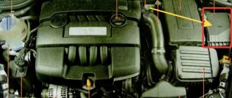
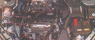
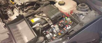
In the engine compartment
All three blocks of the engine compartment are located near the battery. They are marked in the picture above.
Diagram of elements of motor block No. 1
| № | Purpose |
| 11a | (F59) Engine control fuse |
| 11b | (F56) Fuel heater fuse |
| 10 | Exhaust air pump relay |
| 12 | Fuel heater relay |
| 13 | Headlight washer delay relay |
| 14 | Spare |
| 15 | |
| 16,17 18,19 | glow plug relay |
Opel Vectra B engine block relay diagram No. 2
| № | Purpose |
| 1 | A/C compressor clutch relay |
| 2 | Cooling fan relay |
| 3 | Cooling fan timer. |
| 4 | Cooling fan relay |
| 5 | |
| 6 | |
Diagram of elements of motor block No. 3
| Option 1 | |
| № | Purpose |
| 1 | cooling fan |
| 2 | Compressor |
| 3 | cooling fan |
| 4 | |
| Option 2 | |
| № | Purpose |
| 7 | Cooling fan |
| 8 | |
| 9a | Cooling fan fuse |
| 9b | |
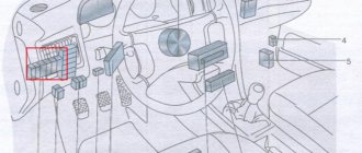
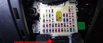
Location of the block and purpose of fuses
The main mounting block of the Opel Grandland https://nizhegorodec.opel.ru/avtomobili/mashiny/grandland-x-my18/index/ B is located in the cabin under the dashboard. To access it, simply remove the protective cover to the left of the steering column. One fuse can protect one or more nodes in the same circuit of the same rating (current in amperes). For installation and connection of additional equipment, backup sockets and connectors for relays are provided.
Assignment of fuses in the mounting block
Fuse number on the block diagram Rated current (amps) Circuit of the protected electrical circuit
| 1 | — | reserve |
| 2 | 30A | Cooling fan drive, air conditioner power circuit |
| 3 | 40A | Heating element on the rear window |
| 4 | — | reserve |
| 5 | — | reserve |
| 6 | 10A | Headlight Level Controller, Low Beam Circuit |
| 7 | 10A | Rear right side light, tail lights |
| 8 | 10A | Right high beam headlight |
| 9 | 30A | Headlight washer drive |
| 10 | 20A | Steering column horn circuit |
| 11 | 30A | Central locking (locking) |
| 12 | 20A | Fog lights |
| 13 | — | reserve |
| 14 | 30A | Wiper blade drive |
| 15 | - the electrical circuit in the block is provided with sockets in the circuit of the same rating (current in amperes). | reserve |
| 16 | 10A | Rear fog light |
| 17 | 30A | Front window drive chain |
| 18 | 10A | License plate light |
| 19 | 20A | Fuel pump circuit |
| 20 | 30A | Rear window drive chain |
| 21 | — | reserve |
| 22 | 20A | Interior lighting circuit, dashboard lighting, radio, hazard warning lights |
| 23 | — | reserve |
| 24 | 10A | Left low beam headlight |
| 25 | 10A | Rear left side light |
| 26 | 10A | Left high beam headlight |
| 27 | — | reserve |
| 28 | — | reserve |
| 29 | 10A | Hazard warning lights, rear view mirror control drive |
| 30 | 30A | |
| 31 | — | reserve |
| 32 | — | reserve |
| 33 | 20A | Output to trailer connector |
| 34 | 20A | Audio auxiliary circuit |
| 35 | 10A | Transmission automatic transmission, ABS |
| 36 | 20A | Heated front seats |
| 37 | 10A | Cigarette lighter circuit in the cabin |
| 38 | 10A | Stop signal |
| 39 | 10A | Automatic transmission sensors |
| 40 | 10A | Fan drive on the radiator of the cooling system |
| 41 | 10A | Heated mirror circuit |
Each fuse is painted a specific color, which corresponds to the rated current:
- 10A – red
- 20A – yellow
- 30A – green
- 40A – orange
When replacing burnt-out fuse links with new ones, you can focus on the color if the markings on the connectors are missing or are difficult to access. The installation of temporary jumpers is not allowed - this leads to short circuits and failure of the remaining electrical equipment, and in a high-voltage circuit, the jumper can lead to a fire. The faulty fuse (fuse link) is removed from the socket with special tweezers, being careful not to damage the wiring. Tweezers are usually included with the mounting block and are located on the side or on any backup connector.
What to do when the cigarette lighter does not work
As already stated at the beginning, the most likely reason for a cigarette lighter failure is a blown fuse. Therefore, we take out the manual for your car, look for the fuse diagram and find the one that is responsible for powering the cigarette lighter socket. It can be either separate or combined with other systems (often it is marked in the form of a cigarette or the inscription Cigar).
“Ring” the desired fuse with a multimeter or test lamp to see if it is working. If there is no device, and the fuse itself does not have obvious signs of burnout, try replacing it with a similar one and checking the cigarette lighter. If it works, change the fuse. No - we are looking further.
Ringing cigarette lighter contacts using a multimeter
The second place that is quite easy to check is the cigarette lighter socket. Carefully inspect it for foreign objects or burn marks on the sides. Further actions will require disassembling the panel and removing the cigarette lighter socket, as well as the presence of a multimeter or at least a test lamp. Don't forget to first remove the negative terminal of the battery!
Disconnect the chip with the cigarette lighter connector from the body and ring the contacts (if necessary, turn on the ignition). If voltage is present, carefully inspect the housing. There may be plaque or oxide on the terminals and connectors of the cigarette lighter, which can be removed with a cotton swab dipped in alcohol (wait for it to evaporate before turning on the device). If this does not help and the socket is clearly burnt out, then only replacing it will help.
The next element that needs to be carefully inspected is the fuse on the cigarette lighter housing. Most often, it has a 90-degree curved shape and connects the cigarette lighter contacts. If it burns out, the problem can be solved using a soldering iron or replacing the housing. In most cases, it is enough to solder or screw a piece of wire (aluminum with a cross-section of 1.5 mm2), which will close the contacts and act as a fuse.
If, when the fuse is working, the “ringing” of the chip with connectors indicates a lack of voltage in the network, then the problem is either in the wires or in the fuse mounting block, in which the conductive paths burn out. Moreover, in domestic cars it is most likely tracks, and in foreign cars it is wires.
To finally verify this, you can go in two ways:
- Disassemble the mounting block and inspect it for damaged tracks. Don't forget to take pictures of how it was originally. If the tracks are damaged, they need to be soldered.
- Find the electrical diagram of the car, find the connectors that come out of the mounting block to the cigarette lighter and ring them. If the voltage goes out and the cigarette lighter does not work, you will have to change the wire, which is quite difficult. If there is no voltage, the problem is in the mounting block.
What to do if the cigarette lighter on VAZ cars does not work?
Since the cigarette lighter socket most often refuses to work for owners of domestic cars, below are some useful tips specifically for VAZs.
Start by inspecting the fuse. It is located in the mounting block in the engine compartment - the exact location can be seen in the diagram of your model:
- VAZ-2104, 2105, 2107 - F6 (8A/10A)
- VAZ-2115, 2114, 2108, 2109, 21099 - F7 (30A) or F4 (20A)
- VAZ-2101-2103 and 2106 - F1 (16A) and the entire 110 family - F6 (15A)
- Lada Kalina and Granta - F20 (15A)
- Lada Priora - F13 (15A), Lada 4x4 - F14 (16A)
- Vesta - F41 (20A)
- Largus - F19 (10A), F20 (7.5A) and F38 (15A)
- Xray (XRAY) – F33 (15A)
Ringing the cigarette lighter fuse using a homemade tester on a VAZ 2107
To determine if the cigarette lighter is faulty on a VAZ, ring the block (black - minus, red - power supply plus, white - plus when the lights are on)
If the fuse is working, also check if there is voltage in its socket.
The next step is to check if there is power at the cigarette lighter terminals. If your cigarette lighter only works when the ignition is on, turn the key in the lock. When the multimeter does not show 12 volts, then the problem is most likely in the tracks of the mounting block. Disassemble it and solder the burnt tracks. Well, if the multimeter shows that there is power, you need to change the cigarette lighter housing itself.
What to do if the cigarette lighter light does not work
As mentioned above, the cigarette lighter light has a separate fuse and a separate wire to supply current to the light bulb or LED. Therefore, first check the corresponding fuse, and if it is ok, disassemble the cigarette lighter and check the wire - most likely it just fell off. There is nothing to burn out here, so the problem can only be in these two places.
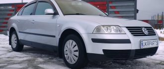
Opel Vectra C (Opel Vectra C) is the third generation of the Opel Vectra model range. Vectra c was produced in 2002, 2003, 2004, 2005, 2006, 2007, 2008. The luxury model Opel Signum was subsequently built on its basis. In this publication you will find a description of the fuse and relay blocks of the Opel Vectra C, with block diagrams and photographs. Let's highlight the fuse responsible for the cigarette lighter.
p, blockquote 1,0,0,0,0 —>
p, blockquote 2,0,0,0,0 —>
The design of the blocks and the purpose of the elements in your Opel Vectra may differ and depend on the year of manufacture, the level of electrical equipment and the country of delivery.
Diagnosis of a faulty electrical circuit
When working with a car's electrical circuit, you must turn off the ignition and battery by removing the minus terminal. The main causes of electrical equipment failures:
- Contact faults (oxidation) at connectors
- Open circuit in wiring sections
- Short circuits
- Unstable grounding (poor contact to ground)
- Relay failure or blown fuse
To diagnose a circuit, use a voltmeter or a 12V tester (you can use a simple probe with an indicator), an autonomous power source and a set of wires with alligator clips. First, check the safety of the fuses and the functionality of the relay - the fuse links are inspected visually, the relay should make a characteristic click when voltage is applied. If all fuses are good, then the problem is in the wiring.
Fuses and relays
color="red"> Warning
Fuse ratings and electrical circuits may vary from year to year.
color=»red»> Fuse location
Fuses
| N | CURRENT STRENGTH (COLOR) | ELECTRICAL CIRCUIT |
| 1 | – | – |
| 2 | 30 (Green) | Air conditioning, cooling fan |
| 3 | 40 (Orange) | Rear window defroster |
| 4 | ||
| 5 | – | – |
| 6 | 10 (Red) | Low beam headlights, light corrector |
| 7 | 10 (Red) | Parking light, rear right side lights |
| 8 | 10 (Red) | Far right light |
| 9 | 30 (Green) | headlight washer |
| 10 | 20 (Yellow) | Sound signal |
| 11 | 30 (Green) | Central locking system |
| 12 | 20 (Yellow) | Fog lights |
| 13 | – | – |
| 14 | 30 (Green) | Wiper |
| 15 | – | – |
| 16 | 10 (Red) | Rear fog light |
| 17 | 30 (Green) | Window lifters |
| 18 | 10 (Red) | License plate light |
| 19 | 20 (Yellow) | Fuel pump |
| 20 | 30 (Green) | Window lifters |
| 21 | – | – |
| 22 | 20 (Yellow) | Hazard warning lights, information display, on-board computer, interior lighting, radiator fan, radio, signaling devices. |
| 23 | – | – |
| 24 | 10 (Red) | Low left beam, light corrector |
| 25 | 10 (Red) | Parking lights and rear left lamp |
| 26 | 10 (Red) | Far left light |
| 27 | – | – |
| 28 | – | Coolant heater (diesel) |
| 29 | 10 (Red) | Hazard warning lights, electrically controlled exterior mirrors, power windows, sunroof, cruise control, interior lighting |
| 30 | 30 (Green) | Luke |
| 31 | – | – |
| 32 | – | – |
| 33 | 20 (Yellow) | Terminal 30: Trailer DC current |
| 34 | 20 (Yellow) | CD changer switch |
| 35 | 10 (Red) | ABS, Traction Control, automatic transmission |
| 36 | 20 (Yellow) | Heated front seats |
| 37 | 10 (Red) | Cigarette lighter |
| 38 | 10 (Red) | Brake lamps, automatic transmission, display, cruise control |
| 39 | 10 (Red) | Automatic transmission |
| 40 | 10 (Red) | Radiator fan, rear window defroster |
| 41 | 10 (Red) | Mirror heater |
Location of the main fuse and relay box on the driver's side instrument panel
| The main fuse and relay box is located under a cover in the instrument panel on the driver's side. |
The location of fuses and relays is shown on the cover.
Each fuse has an inscription indicating the amount of current it allows.
| To remove the fuse, use tweezers to remove the fuse from the connector. Remove the fuse from the tweezers. The wire inside the fuse is easily visible and will be severed if the fuse blows. |
Always replace the fuse with another fuse of the same capacity. Never replace a fuse more than once without determining the cause of the blown fuse.
Relay
A relay is an electronically controlled switch that is typically used as follows:
– the relay can switch high voltage current remotely from the circuit in which this current flows, allowing the use of thinner wires and switch contacts; – a relay can have more than one control input, unlike a mechanical switch; – the relay can perform the function of a timer, for example, it issues an operating interval for the windshield wipers.
Relay location in front of the battery in the engine compartment
| The relays are located in the main fuse and relay box, although some engine related relays are located in the engine compartment. |
If a relay controlled system fails and the relay may be causing the problem, listen to the relay while the system is on. If the relay is working properly, you should hear a click when it turns on. If the relay is working properly, then the cause of the malfunction lies in the elements or connecting wires. If the relay does not work, it means that it is not receiving the main power supply or control pulse, or the relay is faulty.
Removing the relay
To come in
Already have an account? Sign in.
Well, in general it burst, or rather became disconnected at the junction in the area of the corrugation, which compensates for temperature fluctuations of the collector along its length. I’m installing an EGT sensor Threat And she also drove around and kicked some half ass. The hole is 1 cm wide and 6 cm long, she inflated the turbo with 3 pots to 1.3 bar
I do not even know where to start. Yes, I know, I haven’t written anything for a long time, mostly I just read
So this is what I mean, unfortunately over the last six months I haven’t driven my car for a number of reasons, the main one is I can’t park it near the house because a: there are no places, b: where there is I won’t go there. Therefore, I had to part with my girl. But there is a good point, she has a new family in the person of Dmitry / nickname Dmn88 (he will soon be checked and added to our family)
Actually, you can congratulate me on purchasing a vegetable, but I don’t regret it, honest Pioneer, I’m happy with the car
And finally, I’m glad to see everyone
So. In order. We have a 2.8 T engine with a standard turbo. 1. Remove the hose from the actuator, remove the solenoid return hose, unscrew and remove the crankcase ventilation. 2. Unscrew the inlet pipe
3. Unscrew the actuator. There are 2 bolts (like 14)
4. Release its spring from tension. To do this, turn the actuator slightly counterclockwise.
5. Measure the tension of the actuator (distance in green)
6. The tension on the Vectra should be between 4 and 7 mm. On insignia - individually. Usually it was 7+ mm 7. Next, we look at how much we need to pull. For example 5 mm. You need to buy the thinnest washers. 8. Let’s see how long it takes, take the required number of washers, and fasten everything to one upper bolt for now. The washers should be between the turbo mount and the actuator mounting lugs. Those washers should tighten it up. 9. Go for a test drive. Take logs, etc. Drive the same car before and after. If problems arise in the form of gearbox jolts, blowing and other things, then either remove the tension, or remove everything completely and go to specialists in this matter, if everything is ok, then: 10. Unscrew the 4 bolts protecting the hot part. The most difficult bolt is under the coolant reservoir. In the case of VECTRA, remove the battery box.
11. The actuator rod is attached to the gate through a counter washer. (or who the hell knows what it's called). To remove it you need a magnet, long tweezers and a hook. Before removing, cover everything around with a rag so that it does not fly away.
12. She's like the letter "C". We grab it by the hook and drag it towards us6 holding a magnet nearby. Carefully. It is springy and can fly into space. 13. Pull out the actuator.
14. Unscrew the nut 10, which controls the length of the adjustment. Using a caliper we measure how much needs to be added and count the turns.
15. If we tension the actuator, then screw the bushing-mount to the gate onto the rod by the number of turns (turns) that you counted. The nut is 10 loose. Try not to rotate the rod relative to the actuator barrel itself, and also remember the position of the plane of the bushing - the attachment to the gate. 16. Holding the bushing - fastening to the gate, tighten the nut. 17. We attach the bushing - fastening to the gate, slightly pull the tank towards us, put its ears on the turbine mounts. 18. Check how well the bushing-mount fits to the gate mechanism.
16. Take the wire and counter washer, put it on and check the mechanism.
17. Tighten the actuator. 18. Check the right angle of the rod.
19. Putting everything back together in reverse order. 20. If the battery has not been removed, reset the adaptation - remove the “-” terminal for 15 minutes - remove the plug from the brain for one minute. 21. We insert the key / ignition / do not start (do not turn) / turn off / remove the key / start. everything. For example, adjusting the actuator on the insignia optional sport tourer AT 2 people in the cabin Before
So. It happened. There was a full stock Vectra. Even the air filter is original. Let's go. Measured in Windows. Here is a graph from the flywheel.
Then I went to u-power. They did a full exhaust on the 76th pipe from the turbo flange to the nozzles. I went to measure myself again. Here's the result
I didn’t understand anything from the sensations, but on the rahing it gave me a lot. About 3-4 bodies. Then I rode in Zelika with the following cars: AUDI TTS chip - in a move I won its body by 2, instead they brought me a freight train. - 3 bodies. Videos on release
Removing the cigarette lighter and ashtray of Vectra C Restyle 2008.
How to remove the cigarette lighter
Using the Opel Corsa D as an example.
OPEL VECTRA B DISASSEMBLY THE CIGARET LIGHTER AND ASHTRAY TO REPLACE THE LIGHT BULB
Replacing light bulbs in Opel Vectra B
Opel Astra H take out the cigarette lighter and change the light bulb
Replacing the heater panel, opel vectra)
This video was created with the help of YouTube Video Editor (https://www.youtube.com/editor)
Final video on replacing the backlight in the Opel Vectra C
Designation of fuses and relays Opel Vectra
The table shows the fuse number, its factory color and current strength and the electrical circuit for which the fuse is responsible.
| N | CURRENT STRENGTH (COLOR) | ELECTRICAL CIRCUIT |
| 1 | – | – |
| 2 | 30 (Green) | Air conditioning, cooling fan |
| 3 | 40 (Orange) | Rear window defroster |
| 4 | ||
| 5 | – | – |
| 6 | 10 (Red) | Low beam headlights, light corrector |
| 7 | 10 (Red) | Parking light, rear right side lights |
| 8 | 10 (Red) | Far right light |
| 9 | 30 (Green) | headlight washer |
| 10 | 20 (Yellow) | Sound signal |
| 11 | 30 (Green) | Central locking system |
| 12 | 20 (Yellow) | Fog lights |
| 13 | – | – |
| 14 | 30 (Green) | Wiper |
| 15 | – | – |
| 16 | 10 (Red) | Rear fog light |
| 17 | 30 (Green) | Window lifters |
| 18 | 10 (Red) | License plate light |
| 19 | 20 (Yellow) | Fuel pump |
| 20 | 30 (Green) | Window lifters |
| 21 | – | – |
| 22 | 20 (Yellow) | Hazard warning lights, information display, on-board computer, interior lighting, radiator fan, radio, signaling devices. |
| 23 | – | – |
| 24 | 10 (Red) | Low left beam, light corrector |
| 25 | 10 (Red) | Parking lights and rear left lamp |
| 26 | 10 (Red) | Far left light |
| 27 | – | – |
| 28 | – | Coolant heater (diesel) |
| 29 | 10 (Red) | Hazard warning lights, electrically controlled exterior mirrors, power windows, sunroof, cruise control, interior lighting |
| 30 | 30 (Green) | Luke |
| 31 | – | – |
| 32 | – | – |
| 33 | 20 (Yellow) | Terminal 30: Trailer DC current |
| 34 | 20 (Yellow) | CD changer switch |
| 35 | 10 (Red) | ABS, Traction Control, automatic transmission |
| 36 | 20 (Yellow) | Heated front seats |
| 37 | 10 (Red) | Cigarette lighter |
| 38 | 10 (Red) | Brake lamps, automatic transmission, display, cruise control |
| 39 | 10 (Red) | Automatic transmission |
| 40 | 10 (Red) | Radiator fan, rear window defroster |
| 41 | 10 (Red) | Mirror heater |
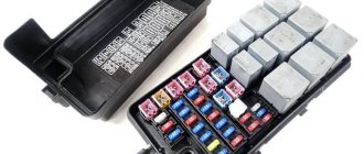
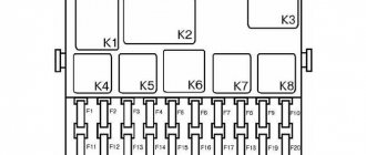
Block in the cabin
The main fuse and relay box is located under the instrument panel on the driver's side and is covered with a protective cover. On the reverse side of which the current diagram will be applied.
Description
| 1 | Jumper (License Plate Lights) |
| 2 | Horn relay |
| 3 | High beam relay |
| 4 | Rear window wiper motor relay |
| 5 | Heated mirror relay |
| 6 | Fog light relay |
| 7 | Rear fog lamp relay |
| 8 | Relay - turn signal switch |
| 9 | Windshield wiper motor relay |
| 10 | Rear window defroster relay |
| 11 | Heater Fan Motor Relay (with A/C) |
| 12 | Heater Fan Motor Relay (with A/C) |
| 13 | Air conditioner relay |
| 14 | Multifunction control unit |
| F1 | — |
| F2 | 30A Heater/air conditioner |
| F3 | 40A Rear window defroster |
| F4 | — |
| F5 | — |
| F6 | 10A/15A Headlight range control, right headlight - low beam |
| F7 | 10A Front right/rear right side lamps |
| F8 | 10A Right headlight - high beam |
| F9 | 30A Headlight washers |
| F10 | 20A Horn |
| F11 | 30A Central lock |
| F12 | 20A Fog lights |
| F13 | — |
| F14 | 30A Windshield wiper |
| F15 | 5A Interior lamps |
| F16 | 10A Rear fog light |
| F17 | 30A Electric window lift |
| F18 | 10A License plate lamp |
| F19 | 10A Audio system |
| F20 | 30A Electric window lift |
| F21 | 10A Audio system, central locking, hazard warning lights, automatic transmission selector lock solenoid valve (“P”) |
| F22 | 20A Air conditioning system, audio system, multifunction display, cooling fan motor, hazard warning lights, instrument cluster indicators |
| F23 | Reserve |
| F24 | 10A/15A Left headlight - low beam, headlight range control |
| F25 | 10A Front Left/Rear Left Side Lamps |
| F26 | 10A Left headlight - high beam |
| F27 | Reserve |
| F28 | 20A Coolant Heater (Diesel) |
| F29 | 10A Power door mirrors, power windows, low beam headlights, turn signals/hazard warning lights, interior lights, instrument cluster, instrument cluster indicators, reverse lights, sunroof |
| F30 | 30A Hatch |
| F31 | 5A Instrument cluster illumination |
| F32 | 10A Daytime Lighting Bulbs |
| F33 | 30A Trailer electrical connector |
| F34 | 10A Audio CD Changer |
| F35 | 10A Anti-lock braking system (ABS), automatic transmission control system, traction control system (TCS) |
| F36 | 20A Air conditioning, seat heaters |
| F37 | 10A Cigarette lighter |
| F38 | 10A Air conditioning system, cruise control, multifunction display, cooling fan motor, brake lights |
| F39 | 10A Automatic Transmission |
| F40 | 10A Air conditioning system, cooling fan motor |
| F41 | 10A Door mirror heater |
Fuse number 37 is responsible for the operation of the cigarette lighter.
How to identify a malfunction
The Opel Astra H boasts a fairly large number of electrical appliances. Therefore, if one or more of them fails, the first thing you need to do is check the fuses. It will not be difficult to identify a faulty one; in the center it will be blackened, possibly slightly melted, and the metal contact in the middle will be broken. Replacement does not require special fuses specifically for the Opel Astra; this part is universal and inexpensive. The main thing is not to make a mistake with the current strength. The number of amperes will be written on the part itself. In addition, the diagram in the Opel Astra H operating manual and color identification will help:
- The purple part can withstand 3A,
- beige - 5A;
- brown - 7.5A;
- red – 10A;
- blue – 15A;
- yellow – 20A;
- transparent – 25A;
- green – 30A;
- pink – 40A.
Fuses blow out most often due to improper operation of the car. For example, when the windshield or headlight washer fluid freezes, the driver begins to repeatedly press the washer control paddle on the steering wheel. The liquid is not pumped, the electricity in the circuit increases, and accordingly the part burns out. The same result awaits the cigarette lighter if you insert several electrical appliances into it at once, or one that is too powerful. Also, the low beam headlight fuse often suffers because the wrong lamp is used.
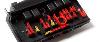
Blocks under the hood
In the engine compartment, next to the battery, there are 3 blocks with fuses and relays.
Check the purpose with your diagrams on the covers of the blocks.
Block 1
Scheme
Designation
- 10 — Exhaust air pump relay
- 12 — Relay fuel heater
- 13 — Headlight washer delay relay
- 14 - Reserve
- 15. – Reserve
- 16, 17, 18, 19 - glow plug control unit relay
- 11a. Engine control fuse (F59)
- 11b. Fuel heater fuse (F56)
Block 2
Scheme
Purpose
| 1 | Air conditioning compressor magnetic clutch relay |
| 2 | Cooling fan relay |
| 3 | Cooling fan timer. |
| 4 | Cooling fan relay |
| 5 | Cooling fan relay |
| 6 | Cooling fan relay |
Option 1
Scheme
Decoding
- 7. Cooling fan
- 8. Cooling fan
- 9a. Cooling fan fuse
- 9b. Cooling fan fuse
Option 2
Scheme
Description
- Cooling fan motor
- Compressor
- Cooling fan motor
- Cooling fan motor
Removal and replacement process
If one of the electrical devices in your car has stopped working, then perhaps the essence of the problem lies in the failure of the link. Of course, the cause of the malfunction may be the device itself, for example, a windshield wiper motor or a malfunction of the headlights. But it makes sense to check the functionality of the power supply element.
To do this, evaluate the part visually. If the fusible thread of the device is broken or burned out, then there should be no doubt: it was he who failed. However, before replacing it, you should make sure that the part will not fail again immediately after its replacement.
PSU for model B at the installation site
To do this, it is advisable to check the functionality of the device whose link has burned out. Perhaps this is the reason. It is also advisable to test the electrical circuit, because there is a possibility that it may have breaks or short circuits. First of all, attention should be paid to areas that have been soldered. Sometimes it is short circuits that can cause regular combustion of power supply elements. If you are sure that the reason lies precisely in the power supply device, then it needs to be replaced. This is done very easily.
- First you need to turn off the ignition.
- Using a screwdriver or your fingers, open the protective decorative cover of your power supply. As you already know, it is located on the left side of the dashboard in the driver's seat area.
- Find the burnt element. To do this, use the diagram marked on the back of the protective cover.
- Using special tweezers, which should be located in the power supply housing, remove the damaged chain link.
- Take the new part and install it in place of the old one. Turn on the ignition and check the functionality of the device that previously failed. If the problem was in the power supply part, then after replacing it everything will work fine. Replace the protective cover of the power supply unit.
Replacing the Z22YH fuel pump from VAZ - logbook Opel Vectra Direct 2.2 l 155hp 2007 on DRIVE2
Hello, I would like to immediately thank you for the maximum assistance provided in helping with the fuel pump.
So! I started the car, waiting for it to warm up, like usual! But after 10 seconds the engine began to shake violently and stalled. I didn’t understand at first. What the hell... I turned on the ignition again and then I realized I couldn’t hear the pump
It’s already 21:00, the shops are all closed, and I’m standing on the other outskirts of the city, I had to take a bus home, I arrived home, abruptly went into Drive and then within 5 minutes they helped me, they wrote that the fuel pump would fit from a VAZ 2110. I called a friend and told him the situation, and in about 20 minutes he arrived with a new fuel pump from 10K, oh MIRACLE! I really didn’t want to leave the car on another part of the city! Let's go, disassemble and replace the pump one to one! No need to cut anything, 650 rubles and the car is running
I’ve been driving with this fuel pump for more than 10 days now and the conclusion is that this car really started to pick up speed more vigorously from 120 to 180 very quickly, taking into account that I don’t have a catalyst, but when accelerating from 120 km to 180 km there are very, very small jerks that are barely noticeable
Yes, I understand the fuel pump from the VAZ is 60 liters per hour, probably this is not enough and the fuel injection pump can be killed. Who knows how many liters per hour the original fuel pump pumps?
Open circuit test:
- One end of the wire with the negative terminal of the tester (probe with indicator) is connected to the negative terminal of the battery.
- The second clamp is attached to the end of the circuit being tested, as close as possible to the fuse connector socket.
- The circuit is turned on by using the element of electrical equipment being tested: if the voltage is stable 12V, then the circuit is operational, if there is no power supply, then proceed to checking the next section. It is worth remembering that some electrical appliances turn on only when the ignition is connected (the key position in the ignition switch is “ON”).
The detected faulty section of the wiring is replaced completely along the entire length from the source to the consumer. Often the reason for the lack of voltage is poor contact on the connector due to the formed oxide; it is cleaned with fine-grained sandpaper, wiped dry and the diagnostics are carried out again.
Replacing the mesh in the gas tank) — logbook Opel Vectra Elegant Chereshnya 2001 on DRIVE2
Now we got around to the filter in the tank. and as it turned out, it was not in vain... the first time I did it, I was stumped for a long time... but I mustered up the courage and got to work...
I removed the rubber plug under the seat and saw a terrible picture...
I had to pick up a vacuum cleaner... then I removed the retaining ring using a hammer and some mother
Next, I had to remove the hoses from the tubes... then a surprise awaited me) there was still pressure left... I was covered in gasoline))) it’s good that there was a reaction and put it back on, took a Big, Big syringe... and began to slowly relieve the pressure and select gasoline with the syringe. Finally we remove the cover...
when I pulled out the fuel pump I saw an unpleasant picture... the screen was covered in trash... and a pile of garbage under the pump screen...
a bandage from my first aid kit came to the rescue)))
to repair a German car, you need German accessories)))
Having removed all the crap from the tank, I installed a new mesh))
Mileage: 204800 km
Circuit short circuit test:
- All electrical equipment is disconnected from the battery power.
- The circuit under test is tested with a voltmeter in the area from the fuse socket; to do this, remove it from the connector and connect the tester instead.
- Next, turn on the circuit: if the indicator light comes on, then there is a short circuit in this section of the circuit. The reason may be broken insulation on the wiring or dirty contacts.
If there is no voltage (everything is fine with the circuit), but the fuse often blows, this means a malfunction in the operation of the electrical equipment element.
Ground voltage test:
- Disconnect the battery.
- One end of the tester is attached to any grounded (connected to ground) element.
- The second end of the tester wire is connected to a part of the car body, or to the section of the circuit being tested: if the current resistance value is zero, then the ground contact is OK.
If poor grounding is detected, inspect the contacts and battery terminals for corrosion, oxides and contamination. It is worth remembering that the circuit should not have breaks, short circuits or loose connections at the contact points.
Sources
- https://carpod.ru/predohraniteli-opel-vectra-b-1995-2003_2937.htm
- https://zapchasti.expert/predoxraniteli/predoxraniteli-opel-vectra-b.html
- https://avtorom.ru/opel-vectra-b-predohraniteli-i-rele/
- https://remocars.ru/opelman/vectra-b/elektrika/blok-predohraniteley-i-rele-opel-vektra-b.html
- https://vsepredohraniteli.ru/opel/vectra-b.html
- https://avtozam.com/opel/vectra/opisanie-predohraniteley/