Despite the primitiveness of the design, replacing the Niva's turn relay and emergency lights occurs almost more often than changing tires for the season. Can we wait? Hardly. Signs of failure manifest themselves in such a way that normal operation of the Niva 4×4 becomes impossible.
As a rule, frequent relay breakdowns are explained by the low quality of components, both supplied from the factory and those still alive “cooperatives”. You can only combat this by choosing carefully or having a handful of other replacement parts.
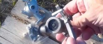
Repair is impractical due to the cheap cost, although there are examples of restoration “for fun.” The only difficulty is access to the place where the Niva turn signal relay is located; changing it is a matter of 2 minutes.
Another reason that can kill the breaker is increased voltage in the on-board network as a result of failure of the generator components and the voltage relay regulator. A short circuit is also possible. In any case, the circuit is examined, starting with a simple one - the state of the fuses.
Expert opinion
It-Technology, Electrical power and electronics specialist
Ask questions to the “Specialist for modernization of energy generation systems”
Relays and fuses Lada 4×4 (VAZ 21214, 21314) Delivery time from 2 to 7 days, depending on the distance of your locality from Tolyatti Delivery cost from 550 rubles. Ask, I'm in touch!
Location
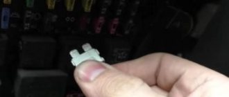
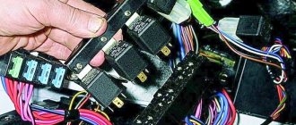
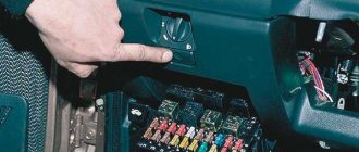
Finding the part you are looking for in a car and then replacing it is not difficult. In 21213 and 21214 it is located in the cabin, behind the dashboard, on its right side. The relay is attached to the body through a stud by tightening the nut to “10”.
Before replacing the Niva turn signal relay begins, disconnect the negative terminal from the battery. Access to the element being replaced is provided by removing the dashboard.
After establishing the location where the Niva turn signal relay is located, unscrew the nut to “10”, simultaneously disconnecting the 3 ground wires from the stud. Pull the device towards you, and then, swinging it slightly, pull out the block. Replace the breaker with a new one as shown in the photo.
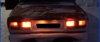
The performance criterion is considered to be the rhythmic flashing of signals after activation of the shift lever or hazard warning button.
A slight deviation of the work rate from the conveyor state 2121 is considered acceptable.
What kind of lighting do you prefer?
Built-in Chandelier
Expert opinion
It-Technology, Electrical power and electronics specialist
Ask questions to the “Specialist for modernization of energy generation systems”
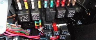
Repeater relays for diode sidelights and headlights with DRLs and dynamic turn signal on Lada Niva from 2022 onwards. buy in the AvtoKlyuch-63 online store at an affordable price. Below the main and auxiliary fuse blocks there is an engine management system relay block, which consists of five relays and one fuse. Ask, I'm in touch!
Electrical diagram of VAZ-21213
1. Front lights.2. Side direction indicators.3. Windshield washer motor.4. Headlight washer motor*.5. Switch.6. Rechargeable battery.7. Starter VAZ-21213.8. Generator.9. Headlights.10. Geared motors for headlight cleaners*.11. Sound signal.12. Spark plugs.13. Carburetor limit switch.14. Carburetor solenoid valve.15. Ignition coil.16. Windshield wiper motor gearbox.17. Carburetor solenoid valve control unit.18. Ignition distributor sensor.19. Coolant temperature indicator sensor.20. Insufficient oil pressure indicator sensor.21. Portable lamp socket**.22. Insufficient brake fluid level indicator sensor.23. Windshield wiper relay-breaker.24. Relay for turning on rear fog light lamps***.25. Relay for turning on the rear window heating element.26. Relay for turning on the headlight cleaners and washer*.27. Relay for turning on low beam headlights.28. Headlight high beam relay.30. Starter activation relay.31. Relay-breaker for hazard warning lights and direction indicators.32. Heater electric motor.33. Additional resistor for heater electric motor.34. Illumination lamps for heater control levers.35. External lighting lamp switch.36. Main fuse block.37. Additional fuse block.38. Reversing light switch.39. Brake light switch.40. Regulator for instrument lighting lamps.41. Ignition switch.42. Three-lever switch.43. Hazard switch.44. Switch for headlight cleaners and washers.45. Heater motor switch.46. Rear window heating element switch.47. Rear fog light switch.48. Lamp switches located in the door pillars.49. Interior lighting lamps.50. Cigarette lighter VAZ-21213.51. Switch for the carburetor choke indicator lamp.52. Indicator lamp for closing the carburetor air damper.53. Switch for the differential lock indicator lamp.54. Parking brake indicator lamp switch.55. Level indicator and fuel reserve sensor.56. Instrument cluster.57. Rear window washer motor.58. Tail lights.59. Block for connecting additional brake lights.60. Blocks for connecting side marker indicators.61. Pads for connecting to the rear window heating element.62. License plate lights.63. Rear window wiper motor.
The order of conventional numbering in the blocks: A - headlight and rear window windshield wipers, windshield wiper relay breaker; B — ignition distributor sensor; B — relay-interrupter for alarm and direction indicators; G - switch; D — three-lever switch; E - hazard warning switch; F - relay for turning on the rear fog light lamps; Z — rear lights; And - instrument clusters of VAZ-21213.
In the instrument panel wiring harness, the second ends of the white wires are brought together to one point, which is connected to the instrument lighting control. The second ends of the black wires are also brought together to a point connected to ground. The second ends of the yellow wires with a blue stripe are brought together to a point connected to terminal “A” of the main fuse block. And the second ends of the orange wires are also brought together to a point connected to terminal “B” of the main fuse block.
Where is the Turn Signal Relay on Niva 21213
Where is the rotation relay, how to replace it Despite the primitive design, replacing the Neva turn and turnstile is almost always more than replacing tires for a season. Can I wait? Barely. Signs of failure appear in such a way that normal operation of the Niva 4×4 becomes impossible.
Reasons for refusal
As a rule, frequent relay failure is due to the poor quality of components, both those supplied from the factory and those still alive "cooperatives". Combating this can only be done by cautiously approaching the selection or having a few other spare parts. Repairs on a dime are not recommended, although there are examples of restorations “just for fun.”
Another reason that can kill the switch is increased voltage in the on-board network as a result of failure of the generator components and the voltage regulator relay. Closing is also possible. In any case, the chain is scanned, starting with a simple one. fuse condition.
symptoms
The symptomatology of the malfunction has its own characteristics and differs from the burning of an incandescent lamp or damage to the circuit. Thus, if the problem is in the relay, then when turning the switch the driver will see one of the following manifestations:
- The indicator does not light up, the turn signals are off;
- The dashboard indicator and turn signals are constantly on;
- When the relay operates, an uncharacteristic crack (clicks) occurs;
- Within a short time there is a change in the pace of functioning;
- Different response rate compared to alarm.
Location:
Find the part you need in your car and then change it is easy. In 21213 and 21214 it is located in the cockpit, behind the instrument panel, on the right side. The relay is attached to the body via a pin, tightening the nut to “10”.
Replacement method
1. Take a screwdriver and loosen the instrument panel valve from the two self-tapping screws.
| №1 | Ignition relay |
| №2 | Main relay |
| №3 | Right cooling fan relay |
| №4 | Left cooling fan relay |
| №5 | Fuel pump relay (fuel) |
| №6 | Fuel pump fuse F5, 15A |
Expert opinion
It-Technology, Electrical power and electronics specialist
Ask questions to the “Specialist for modernization of energy generation systems”
How to convert a relay to LEDs / New video - 2022 1 Ignition relay 2 Main relay 3 Right cooling fan relay 4 Left cooling fan relay 5 Fuel pump relay 6 Fuel pump fuse F5, 15A. Ask, I'm in touch!
The turn signals turned off. Where should I poke the screwdriver?
Shine a flashlight from below to where the vile pin is in the picture and see the relay, then pull out the connector by touch. If the paws do not fit through, remove the instrument cluster. F10 20 A - backup fuse.
F11 5 A - right side lamps. F12 7.5 A - low beam in the right headlight, gear motors for headlight range control. F13 10 A - high beam in the right headlight.
F14 10 A - backup fuse.
13.7.1 Direction indicators and hazard warning lights
F15 20 A - backup fuse. Similar to relay K3. If the brake lights do not work, check this fuse, the lamps themselves, their connectors, usually the problem is bad or oxidized contacts.
Also check the operation of the brake light switch located near the brake pedal. F18 25 A - heater electric motor and its switch.
If the stove blows cold air, the problem may be in the hot air damper, the cable to which comes from the regulator under the casing not far from the gas pedal. The coolant level should be within acceptable limits; the Chevrolet Niva turn signals do not work.
If the heater doesn't work or blow at all, it could be the heater motor. Also check the heater switch and its contacts. F19 10 A - breaker for direction indicators and hazard warning lights in turn mode, indicator light in the light switch, turn signal lamps, turn signal indicator lamps on the dashboard, differential indicator lamp.
Engine control system fuses
It is located on the left side of the body, under the instrument panel, next to the diagnostic block. Consists of four fuses:
| F1 (30A) | Right electric fan relay contacts |
| F2 (30A) | Left electric fan relay contacts |
| F3 (15A) | Relay windings of the right and left electric fans, controller, injectors, ignition coil |
| F4 (15A) | Heating elements for control and diagnostic oxygen concentration sensors, phase sensor, mass air flow sensor, canister purge valve |
Return deadlines
Returns are possible within 7 days after receipt (for goods of good quality).
Return delivery of goods is carried out by agreement.
According to current legislation, you can return a product of good quality or exchange it if:
- the product has not been used and has no signs of consumer use: scratches, chips, abrasions, stains, etc.;
- the product is fully assembled and in its original packaging;
- all labels and factory markings are preserved;
- the product retains its presentation and its consumer properties.
Repeater relays for diode sidelights and headlights with DRLs and dynamic turn signals for Lada Niva from 2022 onwards.
The Availability of Documents sign means that the company has uploaded a certificate of state registration to confirm its legal status as a company or individual entrepreneur.
| Basic | |
| Manufacturer country | Russia |
| Brand | VAZ |
| Type of equipment | A car |
| Model | 2121 |
| Series | Niva (2121) 1976- |
| Compatibility | VAZ 2121 1994-2006, VAZ 2131 1993- |
| State | New |
| dimensions | |
| Dimensions, cm | 3 x 4 x 8 |
| Weight | |
| Weight, kg | 0.05 |
Expert opinion
It-Technology, Electrical power and electronics specialist
Ask questions to the “Specialist for modernization of energy generation systems”
Repeater relay for diode sidelights and headlights with DRL and dynamic turn signal on VAZ 2101-2107, Lada Niva 2123, 21214, 2131 | buy spare parts at low prices with delivery throughout Russia | Skladexpress 1 Ignition relay 2 Main relay 3 Right cooling fan relay 4 Left cooling fan relay 5 Fuel pump relay 6 Fuel pump fuse F5, 15A. Ask, I'm in touch!
Mounting blocks for Lada 4×4 2022
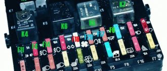
The main and additional units are located in the cabin to the left of the steering wheel, under the instrument panel. The blocks contain fuses of the “Cylinder” size, ten and six fuses, respectively. The ratings and purpose of the fuses are indicated in Table 4 “Circuits protected by fuses”:
Fuse block of standard size “Standard”. The block is located on the left side under the upholstery and contains fuses that are designed to protect engine control system devices. The ratings and purpose of the fuses are shown in Table 5:
The fuse and relay box is located on the left side of the steering column under the instrument panel. The block contains two “Standard” size fuses, which are designed to protect the circuits of the electric fuel pump, electric windows and electric mirrors. The ratings and purpose of the fuses are shown in Table 6:
The fuse and relay box is located on the right side of the steering column under the instrument panel. The block contains one “Maxi” size fuse and two “Standard” size fuses, which are designed to protect the circuits of the hydraulic unit of the anti-lock braking system. The ratings and purpose of the fuses are shown in Table 7:
We cooperate with:
You can find the nearest representative office, track the cargo and calculate the cost of delivery on the website: cdek.ru
You can find the nearest representative office, track the cargo and calculate the cost of delivery on the website: logistics.ozon.ru
You can find the nearest representative office, track the cargo and calculate the cost of delivery on the website: boxberry.ru
Deadline for order delivery to T.K. from 1 to 4 business days from the date of receipt of funds. (orders are not processed on Saturday and Sunday).
Lead time for orders that include painting services: 5-10 business days.
The lead time for placing orders and “made to order” items is from 14 days; you can check with the manager for more detailed information.
Orders for pickup are placed on the website, the formation time is on average 1-4 business days, after the items arrive at the pickup point, the manager will notify you when you can receive your order.
ATTENTION! All fragile goods (headlights, plastic products, glass, etc.), by default, are sent in additional paid packaging from TK. If you take responsibility for the integrity, we can ship without it. To do this, you need to make a note in the comments when placing your order. For additional information, please contact the managers.
Expert opinion
It-Technology, Electrical power and electronics specialist
Ask questions to the “Specialist for modernization of energy generation systems”
Replacement method Main Country of origin Russia Brand VAZ Type of equipment Passenger car Model 2121 Series Niva 2121 1976- Compatibility VAZ 2121 1994-2006, VAZ 2131 1993- Condition New Overall dimensions Dimensions, cm 3 x 4 x 8 Weight Weight, kg 0. Ask, I am in touch!
Mounting blocks for Lada 4×4 2022
Turn signal relay
(part number 8450082700, 9-pin), as well as the windshield wiper relay, are located under the trim in the driver’s feet, to the left of the fuse mounting block. Also, the turn signal relay can be located behind the instrument cluster, or under the center console closer to the left side.
Attention!
The relay and fuse diagram may differ depending on the configuration and production date of the vehicle. Current diagrams of the mounting block are presented in the operating manual for the date of manufacture of the car (download from the official website for 3-door or 5-door).
Why does a fuse or light relay or any other constantly blow out? Before replacing it with a similar one, you must first find and eliminate the cause of its burnout. This could be a short circuit, incorrectly selected rated current, etc. Use electrical circuit diagrams to troubleshoot problems. Questions on this topic can be asked on the forum.
Keywords: 4x4 mounting block | dashboard 4x4
2 0 1 0 0 1
Share on social networks:
Do-it-yourself repair of direction indicators and hazard alarms
If the turns disappear, as well as the car’s emergency signal, then you can try to solve this problem yourself:
- If the safety element and relay break down, the failed parts must be replaced. If the reason lies in a short circuit, then before replacing it is necessary to check all electrical circuits in which it could occur. Only after the cause of the short circuit and power surges has been eliminated, the devices need to be changed.
- If the hazard warning button is faulty, you just need to replace it. We have already talked about how to diagnose this part.
- As for electrical circuit diagnostics, it is carried out using a tester. If damaged sections of the wire are identified, they must be replaced. When laying them, make sure that the wiring does not come into contact with moving body elements. It is also recommended to additionally insulate new wires to increase the reliability of the insulation.
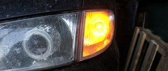
- If the reason is the light bulbs, then all burnt out light sources must be replaced. In the front and rear headlights, the lamps are changed by removing the protection from the headlights, disconnecting the power circuit from the lamp, as well as unscrewing the light source from the seat and replacing it with a new one. If the lamps in the side headlights do not work, then, as a rule, to dismantle the lighting sources, the lamp itself must be pryed off with a screwdriver, then disconnect the power cord and remove the device.
- If the reason lies in the steering column switch, then this device needs to be disassembled and checked. As a rule, the cause of switch failure is poor contact or abrasion. In this case, the failed switch is replaced with a new one. As for the contacts (no matter where - on connections or buttons), it is advisable to clean them.
- You should also check all the plugs and connectors, because it is quite possible that the problem is poor contact on them. Acidified contacts must be cleaned with a wire brush or sandpaper. If the contacts are burnt out, they will need to be replaced.
Also interesting: What to do if the right or left power window does not work in a Chevrolet Niva
Loading …
The video below presents an inexpensive option for repairing the steering column switch in a Peugeot car (the author of the video is the EzjikOnline channel).
Replacement method
For operations you need:
- Key head to “10” (preferably with a ratchet mechanism);
- Plastic puller or similar device;
- Pliers;
- Phillips screwdriver.
- 1. Take a screwdriver and loosen the instrument panel from the two self-tapping screws.
2. Carefully apply the shield to yourself, overcoming the resistance of the pair of latches at the top of the part.
3. Unscrew the dashboard using the “10” key.
4. Slowly dismantle the instrument cluster, while at the same time getting rid of the union nut of the flexible speedometer drive shaft using pliers.
5. Disconnect the wires by removing the two gaskets.
After establishing the place where the relay turns to the Niva, unscrew the nut to “10”, by the way, disconnect the 3 wires from the “ground” from the stud. Pull the device towards you and then, using a slight swing, pull the shoe out. Replace the switch with a new one as shown in the photo .
Fuse box VAZ Niva old and new model
The main difference between the schemes of old and new Niva lies in the method of connecting the additional mounting block, which is located below. If in older models only two fuses are used for this purpose, then in the updated ones there are already four.
In general terms, the difference between the two blocks looks like this:
| New additional block | Old additional block | ||||
| Fuse no. | Current (amps) | What is he responsible for? | Fuse no. | Current (amps) | What is he responsible for? |
| 11 | 8 | Turn signal lamps, relay-breaker for turn signals and emergency lights | 11 | 8 | Reserve |
| 12 | 8 | Daytime running light relay, Daytime running light bulbs | 12 | 8 | Reserve |
| 13 | 8 | Rear fog lights and their relay | 13 | 8 | Fog lights and their relays |
| 14 | 16 | Cigarette lighter | 14 | 16 | Cigarette lighter |
| 15 | 16 | Reserve | 15 | 16 | Reserve |
| 16 | 8 | Reserve | 16 | 8 | Reserve |
Read more about electromagnetic-thermal relays
Such a relay is designed to be simple and reliable, although it is not without its shortcomings. Owners of some particularly old VAZ cars changed it at most once or twice. It's all about the reliable design of the relay, which is a kind of metamorphosis of devices used in industrial installations. The key elements of such a relay are the following:
- A cylindrical core having a winding of particularly thin copper wire;
- Two contact groups at the top of the core;
- Metal anchors on the sides;
- Metal body.
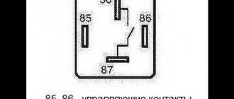
There are two contact groups, and the first is responsible for closing the circuit of the car turn signal indicator light on the dashboard, and the second group is directly responsible for the circuit of the turn signal light bulbs. In normal condition, the direction indicator circuit is normally open, because the anchor of the contact group is pulled off with a nichrome thread. The thread is fixed on an insulating material, from which the platform for installing the core is also made. There is a current in the same thread - it is connected to the pointer switch circuit.
An electromagnetic-thermal relay operates on a fairly simple principle. As soon as the signal to enter a turn is received, the circuit is closed. The circuit includes turn signal bulbs, a relay winding, a resistor and a nichrome thread. A resistor is needed to reduce the current. As soon as the material (nichrome) begins to heat up, the thread made from it begins to stretch. Since the anchor is pulled by a thread that gradually increases in length, it will be able to close the contact group after some time. Now the current begins to bypass both the nichrome thread and the resistor - it simply begins to “flow” bypassing areas with high resistance. This means that the direction indicator lamps begin to burn not at half-glow, but at full strength. It is important to note here that nichrome thread heats up and cools down very quickly. Due to this feature, the lamps can flash 60-120 times per minute . As the reader probably guessed, the opening of the contacts is due to the fact that the thread has time to quickly cool and pull the armature away from the core. When a signal is given, everything repeats.
Why are there two contact groups in the relay? Everything is very simple. The fact is that one position of the contact group directly affects the work of the second contact group . Once the contacts of the first group are open, the armature in the second group cannot close it. When the current increases and the thread stretches, the first contact group closes, which is a condition for the attraction of the armature in the second group. As a result, both the direction indicators and the warning light mounted on the dashboard begin to flash.
As for sound signals, everything is simple here: the armature closes and opens the circuit not smoothly, but rather abruptly, as a result of which the driver and passengers can hear dull clicks. This is a feature of the operation of electromagnetic relays, which made it possible to save on additional sound warning devices. The relay body is made of metal and has a cylindrical shape. At the bottom of the cylinder there is the already mentioned platform, which has insulating properties. Through the lower part of the platform, contacts are output that must be included in the direction indicator circuit.
Self-diagnosis of car lighting devices
There are several situations in which you can determine that optics need diagnostics:
- The turns do not flash, but light up. Such a malfunction indicates the failure of the relay, in particular, we are talking about its electromagnetic component. The electromagnet itself could close in one of the positions, as a result of which it cannot return to its initial state.
- The turning lights flash very quickly or very slowly. In this case, the problem may lie not only in the relay. In some cases, this type of malfunction occurs when the driver uses inappropriate lighting sources. So when purchasing new light bulbs, you need to make sure that they correspond to the rating set by the car manufacturer.
- The optics don't work at all. That is, the turning light bulbs do not flicker, and the corresponding indicators on the dashboard also do not light up. In addition, there are no characteristic clicks that appear when turning on the turning lights. With such symptoms, there can be many reasons for the problem; we will tell you more about their diagnosis below (the author of the video is the Steel Horse channel).
As for diagnostics, it is performed in several stages:
- First of all, you need to make sure that all sensors and indicators on the device are working. If they do not function, then it is necessary to diagnose the safety devices.
- If all devices are operating in normal mode, then you next need to turn on the light alarm button and diagnose all light sources in the headlights. That is, check the front, rear, and side (if any) lights.
- If the alarm does not function when activated, you need to check the functionality of the relay, and also check the power supply at the terminals. To do this, remove the relay from its mounting location, and then, using a test light, connect one of its contacts to the installation site (to the positive), and the other to the car body or battery. There is no need to turn on the ignition. If there is no power, then most likely the reason lies in a failed safety device, a broken hazard warning button, or a damaged electrical circuit. Also, the essence of the problem may lie in poor contact in the connecting plugs.
- If there is a plus on the contacts, then try shorting the two relay terminals using copper wiring. If all electrical circuits, as well as the connection plugs, are working properly, then all turn signals should light up. In this case, the fault must be looked for in the relay.
- If the lights do not light up after the steps you have performed, then most likely the cause of the malfunction lies in the emergency light control button. However, in practice this happens quite rarely; there is often a short circuit in the circuit. By the way, it is a short circuit that can lead to a breakdown of the relay, therefore, before replacing the failed element, you need to eliminate the short circuit.
- If the emergency signal is functioning, this indicates that the safety devices and relays are working; accordingly, you need to start diagnosing the button itself. First of all, you need to diagnose the positive terminal, as in the case of checking the relay, while the ignition, as well as the hazard warning button, must be activated. If the diagnostics showed that there is no plus, this indicates that the button itself needs to be checked in more detail. Remove it from its seat and check the connection circuit. If there is no power, then you need to look for a break in the wiring from the tidy to the button itself. If there is power, then it will be necessary to short-circuit the terminals at the installation site, the ignition does not turn off, after which the direction indicators must be activated (on either side). When the lighting sources are turned on, the control button must be replaced, but if there is no power, then you need to check the power in the emergency relay. If there is no power, the problem most likely lies in a break in the connecting electrical circuit from the control key to the block with safety devices.
And also interesting: Technical characteristics of VAZ 2121 (4x4) 21214 1.7 MT 4WD, 83 hp. (2002-2020 production) - all about this car on the website