The giving of turn signals is provided for in paragraphs 8.1 and 8.2 of the Rules of the Road. Turn on your turn signals not only before turning and changing lanes, but also before starting to move or before stopping at the edge of the roadway. Failure to comply with these rules can lead to an accident, therefore, a fine is provided for failure to turn on turn signals (Article 12.14 Part 1 of the Code of Administrative Offenses of the Russian Federation). The driver must monitor the technical condition of the turn signal system. For this, knowledge of its structure will be useful.
Purpose of the turn relay
The Traffic Rules in force in Russia clearly state that when making maneuvers, it is necessary to turn on the direction indicators, and in their absence, indicate the direction of movement with your hand. However, now most cars and motorcycles are equipped with turn signals, so you rarely need to use your hands to indicate the direction of travel.
When turned on, the direction indicators flash, that is, they light up and go out at certain intervals, so they attract the attention of other road users, and it is quite difficult not to notice the turn signal being turned on. The blinking of direction indicators also serves another role - it does not allow drivers to confuse their activation with the activation of brake lights or the activation of side lights.
Periodic turning on and off (that is, the same blinking) of the direction indicator lamps is realized using a simple device that is part of the vehicle's electrical system - a turn relay, which is often simply called a breaker or breaker relay.
The breaker relay included in the turn signal circuit performs three functions at once:
- Supplying electric current to the direction indicator lamps (that is, turning on the “turn signals”);
- Ensuring intermittent operation of the direction indicator lamps (their blinking);
- Creation of characteristic clicks, signaling to the driver of the car that the direction indicators are working.
In cars of the Volzhsky Automobile Plant of various generations and models, several types of turn relays are used, which have different operating principles and characteristics.
Turn relay VAZ, GAZ (installed in the unit) AVAR
300 ₽
Turn relay VAZ-2108,2110,GAZ-31105,GAZelle Next EMI
170 ₽
Turn relay VAZ, GAZ AVAR
390 ₽
Turn relay VAZ-2104,05,06,07 4-pin. AUTOPRIBOR
480 ₽
Turn relay VAZ-2108,2110 EM
220 ₽
Turn relay VAZ-2101-03 AVTOPRIBOR
290 ₽
Turn relay VAZ-2104-07 AENK-K
240 ₽
Turn relay VAZ-2108-10, M-2141 AUTO RELAY
125 ₽
Turn relay VAZ 04,05,07 1111 (781.3777) (4-pin) SOGDIANA
80 ₽
Turn relay AUDI 100 BOSCH
1 328 ₽
This is interesting: Refilling car air conditioners - instructions for a comfortable climate!
What is a turn signal switch used for?
Traffic regulations indicate that each driver, planning to perform a particular maneuver, is obliged to notify other drivers of his intentions. Once upon a time, when cars were still a curiosity, such notifications were given with the left hand (when driving on the right). If the arm was extended, this meant the driver wanted to turn left when it was bent and the fingers were pointing up - to the right.
With the increase in the number of cars, traffic rules and lighting devices were improved, not only making it easier to move in the dark or in conditions of reduced visibility, but also signaling to other participants about a change or suspension of movement.
Traffic change signal
Cars began to be equipped with light direction indicators, which were supposed to pulsate to attract attention. To prevent the devices from constantly shining, but from blinking periodically, a small device was invented, which later became known as a pointer breaker or rotary relay. Despite the fairly large number of varieties of the mentioned device, their functions are similar: supplying a pulsating impulse to the turn signal lamps and signaling with clicks that they are on.
P O P U L A R N O E:
- Powering a laptop in a car
- DIY subwoofer
If your laptop does not have this feature, the device described here will help. It provides an output voltage of 16.5 V at a current of up to 4 A. More details…
Types of breakers and their features
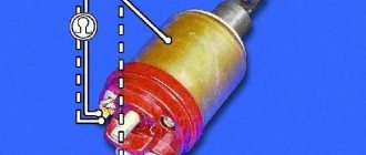
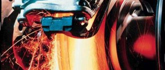
Modern rotary relays are mainly divided into two types: thermoelectromagnetic and electronic. Each device has its own advantages and disadvantages, and this will be discussed. Thermal electromagnetic relays contain a core with two contact groups and side armatures. In addition, they have a copper wire winding. The contacts leading to the light bulbs are connected to a thin nichrome wire, which, in turn, is connected to a plate that is connected to the core.
In the normal state, when no current flows into the circuit, the plate is not adjacent to its base. When the electrons begin to move, the nichrome wire heats up, elongates, and shorts the core plate. The lights come on. Afterwards, the nichrome cools down, the plate comes off again, the current changes direction, and the light bulbs burn at full intensity. Since the cooling-heating process occurs quite quickly, 1-2 times per second, the turn signals blink. Since the light bulb located on the instrument panel is also connected to the circuit, it also begins to pulsate. The specific clicking of the breaker is a consequence of the cyclic impacts of the armatures on the contacts.
Flashing car turn signals
A relay of this type was installed on all cars for quite a long time, but it had (and has) a significant drawback. Over time, the nichrome wire stretches and the turn signals no longer work. Besides this, there is another point. If one of the light bulbs burns out, the load on the others increases significantly. In recent years, thermoelectromagnetic relays are practically no longer installed on cars. They have been replaced by more reliable electronic breakers.
Electronic turn signal relays are built on the same principle as thermal ones, but instead of a nichrome wire, there is an electronic circuit made of transistors. The control chip contains an algorithm that produces automatic pulses that, at certain moments, supply current to the core winding. The operation of the device itself is as follows: after voltage is applied to the transistors, frequency pulses are sent from them, having the oscillations that are set by the program in the microcircuit. As the current passes through the circuit, it attracts the armature, closing the contacts leading to the lighting fixtures, causing the bulbs to light up. Since the cycle consists of signals of different frequencies, they either work at full intensity or dim.
Electronic turn signal relay
The advantage of electronic breakers is that they are more reliable than thermal ones. In addition, if one of the light bulbs in the circuit burns out, the others continue to work without unnecessary load. True, in some cars the circuit is designed in such a way that in this case the warning lamp on the instrument panel stops blinking. This is done specifically to additionally signal a malfunction. True, there are some disadvantages here too. First of all, such a relay creates radio interference and can affect the operation of many devices. The second negative factor is that the short circuit protection here is very weak, and at the slightest drop in electrical voltage the breaker can easily burn out.
Electronic relay device
To better understand the operating principle of an electronic relay, it is better to understand the features of an electromagnetic-thermal relay. Here's an example: in the first device there is a nichrome thread, but in the second its functions are performed by an electronic key. All electronic relays can be divided into two components:
- Directly an electromagnetic relay responsible for closing and opening the circuit;
- An electronic key that ensures that the relay operates at a strictly defined frequency.
The above electronic key is based on a microcircuit or many transistors, also called discrete elements in professional language. This basis forms the control circuits and the master oscillator. And all for the sake of one thing: supplying and removing voltage from the winding of an electromagnetic relay already familiar to us.
The system works relatively simply. As soon as voltage is applied to the relay, the master generator is switched on. It generates control pulses of a certain frequency, which are supplied to the control circuit. The latter supply or interrupt the current coming from the relay winding. When current flows in the winding, the relay armature is attracted, thereby closing a pair of contact groups. At this moment, the direction indicators and warning light come on. As soon as the current stops its action, the armature moves back to its initial position and both contact groups open. Electronic relays have nevertheless replaced their electromagnetic-thermal “brothers”. There are several reasons for this, which are discussed below. In the meantime, we advise you to pay attention to the image - this is the simplest circuit in which a turn relay is implemented. Understanding the circuit will be helpful when repairing a broken relay.
Circuit assembly
The entire circuit is assembled on a miniature printed circuit board measuring 35 x 20 mm; it can be manufactured using the LUT method. The tracks must be tinned after etching, then the copper will not oxidize.
First of all, resistors and a diode are soldered onto the board. After them, everything else is a pair of transistors, electrolytic capacitors and a terminal block. It is important not to confuse the pinout of the transistors and the polarity of the capacitors, otherwise the circuit will not work. When all the parts are soldered onto the board, be sure to wash off the remaining flux and check the correct installation.
If turn signals and emergency lights do not work: common faults and their elimination
Turns relay
Until recently, the main element of turn signal and hazard signal systems was the turn relay. In the middle of the last century, turn relays with a bimetallic plate were used. In some models of budget cars and trucks they are still used to this day. Along with simplicity and low cost, they are more reliable and maintainable. A typical relay circuit is shown in the figure:
The core of the circuit is a bimetallic strip. It is included in the circuit of current flow through the turn lamps. When turning on the turns or emergency lights, it is in a non-heated state, and closes the circuit of the warning lights, they turn on. As the bimetallic plate is heated by the flowing current, it changes its geometric dimensions (bends).
A little physics: a bimetallic plate consists of two (bi) bonded plates with different coefficients of thermal expansion. When both plates are heated, one expands more, the other less, hence the deformation. When bending, the plate opens the relay contact, the current stops flowing, the lamps go out, the plate cools down again, the contacts close, the lamps light up, the plate heats up... So ad infinitum. If one of the lamps burns out, the current will be less, the plate will heat up more slowly, and the blinking period will increase. If there is a short circuit in the circuit, the lamps will flash quickly. Everything is very simple, reliable and informative. Such relays have been used for more than half a century.
Nowadays, combined relays with a built-in electronic circuit are used.
Such circuits are less reliable and often fail, especially from unknown manufacturers. Relays are usually mounted either on the steering column or in the fuse box under the dash. This is done so that their operation can be heard by the driver. In modern cars, there is an additional buzzer in the dashboard that duplicates the turn indicators. Such relays cannot be repaired; they must be replaced.
Video - what to do if the turn signals and emergency lights of the VAZ 2114 do not work:
Turn switch
Another, no less important, element of the turn signal system is the switch on the steering column. It is usually reliable, but given the frequency of its activation, especially in urban traffic, it often fails.
In order to replace it, you need to remove the plastic steering column protection cover. The switch is usually secured with latches, sometimes with screws. Dismantling is not difficult.
Some craftsmen undertake to repair them. It’s better to change it right away, maybe for a used one, if there is no other option.
Faulty wiring, lamellas, lamps
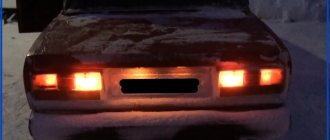
Detecting the location of electrical wiring damage is difficult because the system serves the rear parking lights. The wires to them go through the interior; often the lamps are located on the trunk door. The most common places for electrical wiring damage are:
- under the thresholds, especially the driver's and front passenger's;
- in the corrugated adapter for wiring to the trunk lid;
- in the connector of headlights and lamps.
If one of the light bulbs does not light, first of all you need to ring it; if it is working, tighten the slats and contacts of the socket into which the light bulb is inserted.
Modern cars often use LED emitters. Despite the high reliability of LEDs individually, emitters as part of an LED line often fail. It is better to contact specialists for repairs. You can solve the problem yourself by replacing the faulty diode in the line. Its power is usually in the range from 0.2 to 1.0 watts.
Hazard switch
If it is not operational, all lamps may flash when the turns are turned on. This is also possible with a faulty turn switch on the steering column. In some cars, such as the VW Passat, the turn signal relay is located in the emergency button.
The cost of such a new button is small; in case of malfunction, it is better to replace it with a new one.
Malfunction or software failure of the body control unit
In cars produced after 2010, sometimes the functions of switching turn signals and activating the hazard lights are transferred to the body control unit. On the one hand, this is correct: centralized control is required. But this makes system repair much more difficult. Firstly, it is no longer possible to do without computer fault diagnosis. Secondly, to eliminate the malfunction, you will most likely have to “get into” the body control unit; this should only be done by an experienced specialist.
Blown fuses
The fuses that serve the turn signal and hazard warning systems rarely fail. If they burn out, it is necessary to check the condition of the wiring, lamp contact lamellas, and replace the fuse accordingly.
The most common malfunctions and their causes
- The hazard warning lights work, the turn signals do not turn on - there is a malfunction of the turn switch;
- The turn signals work, the hazard warning lights do not work - the turn signal button is faulty;
- Neither the turn signals nor the emergency lights work - there is a malfunction of the turn signal relay (or poor contact), blown fuses, failure of the body control unit;
- increase in the blinking frequency of indicator lamps - short circuit of wiring, lamellas of turn lamps;
- reduction in the blinking frequency of indicator lamps - broken wiring to the turn signal lamps, burnt-out lamps, poor contact in places where lamps are installed, connectors, failure of LED strips.
This is interesting: The throttle sensor on the VAZ 2110 is an important device
We are looking for a breakdown with our own hands
Primary diagnostics can be carried out with a test light, but a tester is required to check the condition of the circuit. If you know how to use a multimeter, then in resistance measurement mode you can independently “ring” the wiring for a break.
The search for the reason why the turn signals and emergency lights stopped working should begin with studying the electrical circuit. We recommend that you refrain from self-repair if you are unfamiliar with the basics of electrical engineering and methods for restoring wiring.
If you clearly hear the relay clicking when you turn on the right/left turn signal, check the resistance of the section of the circuit with the steering column switch. If only the left or right side does not work, the reason is definitely in the switch or in the wiring of the circuit from it to the light bulbs.
If the turn signal relay does not click at all, check the condition of the contacts, the positive wire and ground. If, after turning on the ignition, “+” does not come to the relay, the problem is most likely in the section of the circuit from the mounting block to the relay.
Understeering's shifter
The cause of the malfunction can be either mechanical damage to plastic or contact elements, or the formation of carbon deposits. During operation of the turn signals, the contacts may burn out, which increases the resistance and reduces the current in the circuit. It is typical that in the case of oxides and carbon deposits, the indicator relay may click, but the lamps will not light up.
To repair the steering column switch, you will need to remove it from the steering column and disassemble it. There are many contact pads inside the case, so for trouble-free assembly, remember the location of all moving elements.
Removal and installation of pyrotechnic products requires compliance with safety regulations. Therefore, we recommend reading how to properly remove the airbag.
Where is it located and how to check the turn signal relay
The turn signal relay is located in the fuse box in the passenger compartment or under the hood. You can find out the exact location from the repair and operation manual of your car. Often on the inside of the mounting block the purpose of the relays and fuses is graphically depicted.
Soldering of elements from the circuit, microcracks in solder joints, failure of the main microcircuit are the most common causes of turn signal failure.
Emergency crew
The hazard warning button imitates the steering column turn switch, but closes both contacts at once (on the right and left sides). The video shows the design and operating principle of a simple system, analogues of which are used not only on VAZ cars.
Turn signal malfunctions - symptoms
- The absence of flicker is one of the obvious and frequent signs of device failure.
- No shutdown when turning the steering wheel.
- Very frequent blinking (often the cause may be a burnt-out lamp, or the power of the lamp does not correspond to the rating)
- Annoying clicking sound.
- Turn indicator dimly lit.
- Lights up but doesn't blink.
- Sticking.
- The hazard warning button is faulty.
To eliminate the causes of the turn signal malfunction, it is necessary to check and, if necessary, replace the VAZ turn signal relay.
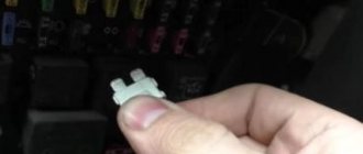
Removing relay type 494.or 642.3747
1. Under the instrument panel on the driver’s side, disconnect the connecting block from the turn signal relay
2. Using a 10mm wrench, unscrew the nut and remove the relay.
Diagram for checking the presence of voltage in the relay block
Relay test circuit
Electronic breakers type 494.3747 and 642.3747 do not require maintenance during operation.
These breakers cannot be repaired; if they fail, they must be replaced.
Relay test
Install the new relay in reverse order.
Replacing the turn signal relay for a VAZ 2107
The design of the relay does not provide for the possibility of its repair.
If a malfunction is detected, the part must be replaced. If the relay is located in the mounting block, to replace it, simply follow these simple steps:
- open the cover of the mounting block;
- pry with a screwdriver and remove the old relay;
- install a new relay;
- close the cover of the mounting block.
If the relay is located behind the dash, it is much more difficult to replace. To avoid a short circuit, it is better to disconnect the ground wire from the battery. Replacing the turn signal relay is done as follows:
- Unscrew and remove the button (handle) of the daily mileage counter.
- Remove the decorative handles from the interior heater control levers.
- Remove the decorative plug from the dashboard mounting screw.
- Unscrew the screw.
- Unclip the dashboard fasteners by prying it up with a screwdriver.
- Unclip the wire connectors from the instrument panel.
- Unscrew the speedometer cable by hand.
- Remove the dashboard.
- Unplug the wire terminals from the relay by turning.
- Unscrew the relay mounting nut.
- Connect wire terminals
- Reinstall the relay and tighten the mounting nut.
- Connect the wire terminals to the dashboard.
- Screw the speedometer cable to the dashboard.
- Place the panel in place by snapping the fasteners into place.
- Tighten the screw that secures the dashboard.
- Install decorative handles on the heater control levers.
- Screw on the trip odometer handle.
- Install the decorative plug onto the self-tapping screw.
After this, you need to connect the ground wire to the battery. Replacing the turn signal relay is now complete.
Turn signals are perhaps a very important part of any vehicle. Carrying out maneuvers on the road becomes quite a dangerous task if
The VAZ 2107 turn signal and hazard warning relay is responsible for the correct operation of the direction indicators. This device is used on all cars of the classic family. Let's consider why a turn signal relay is needed, how is a relay malfunction determined and how is it replaced?
Breaker relays, LEDs and buzzer
Recently, many cars began to use LED lamps as lighting elements in turn signals. Attempts by our “craftsmen” to simply replace them with light bulbs lead nowhere. Many people have absolutely no idea how the relay itself functions, and have absolutely no idea that it needs a little additional work.
Modification of the turn signal relay
Anyone who is familiar with radio electronics and has experience assembling radio devices knows what to do - you need to solder a small electronic board into the breaker, the circuit diagram of which is available on the World Wide Web. If you don’t have the skills to communicate with semiconductors, then if you want to use LEDs instead of ordinary light bulbs, it’s best to contact a car service specialist.
Another interesting solution today is the sound module for the direction indicator. In this case, instead of measured clicks there will be other signals. Some craftsmen build a sound alarm themselves; the circuit is quite simple, and the components are not difficult to find. The main thing is to connect it correctly into the circuit. There are, of course, commercial versions; with this purchase you can also configure the type of backup turn signal signaling. Most new cars come with a sound breaker as standard.
Home →
Device →
Electrical system →
Headlights and lamps →
The nuances of turning on running lights
And the more parts, the less reliability. I do not recommend connecting DRLs using this scheme. This seems complicated, but let's look at an example and everything will become clear. Now, if you try to start the car with the security switched on, contact 30 will open with contact 87A and will not allow the engine to start. You have no way to turn off the DRLs until you remove the key from the ignition. Actually, the current reserve never interferes - but this mainly applies to some kind of non-standard electrical equipment of the car that is connected independently. Likewise, 14.8 volts, to which the voltage in the on-board network rises when the engine is running, does not harm them. Its polarity is indifferent to the relay. In this form, the scheme has a significant drawback. There are, of course, more complex relays, with several groups of contacts in one housing - making, breaking, switching. Signal inversion and load control circuits. We connect to low-current transistor alarm outputs. We connect the other end of the wire to pin 87A. How a 5-pin relay works and works
Causes of malfunctions
Malfunctions of the turn relay are usually associated with a violation of the electromagnetic patency in the relay itself. The cause may be burnt or shorted contacts, swollen capacitors, failure of the electronic circuit, etc. Typically, the cause of relay failure can be identified by the characteristic manifestations of the malfunction.
- If the turn signals are constantly on and do not blink, then most likely the cause of the malfunction is a breakdown of the electromagnetic part of the relay. Most often, this is due to shorted contacts due to their burning.
- Unusual blinking of the turn signals (too fast or too infrequent) may also be due to the turn signal relay. However, in this case, you can look for the problem in other places. Possible reasons for this behavior of the indicators may lie in oxidation of the lamp socket or base, or a break in the wire going to the lamps. This phenomenon also often occurs after replacing standard incandescent lamps in direction indicators with LEDs. If none of these possible reasons is confirmed, then, most likely, the breakdown still lies in the relay.
- Another option for incorrect operation of the turn relay is that the indicator lamps do not light up at all. This phenomenon occurs when the relay contacts burn out. However, this manifestation of a malfunction is also typical for other breakdowns: a blown fuse, an open circuit or a broken turn switch.
Read more about electromagnetic-thermal relays
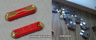
Such a relay is designed to be simple and reliable, although it is not without its shortcomings. Owners of some particularly old VAZ cars changed it at most once or twice. It's all about the reliable design of the relay, which is a kind of metamorphosis of devices used in industrial installations. The key elements of such a relay are the following:
- A cylindrical core having a winding of particularly thin copper wire;
- Two contact groups at the top of the core;
- Metal anchors on the sides;
- Metal body.
There are two contact groups, and the first is responsible for closing the circuit of the car turn signal indicator light on the dashboard, and the second group is directly responsible for the circuit of the turn signal light bulbs. In normal condition, the direction indicator circuit is normally open, because the anchor of the contact group is pulled off with a nichrome thread. The thread is fixed on an insulating material, from which the platform for installing the core is also made. There is a current in the same thread - it is connected to the indicator switch circuit.
An electromagnetic-thermal relay operates on a fairly simple principle. As soon as the signal to enter a turn is received, the circuit is closed. The circuit includes turn signal bulbs, a relay winding, a resistor and a nichrome thread. A resistor is needed to reduce the current. As soon as the material (nichrome) begins to heat up, the thread made from it begins to stretch. Since the anchor is pulled by a thread that gradually increases in length, it will be able to close the contact group after some time. Now the current begins to bypass both the nichrome thread and the resistor - it simply begins to “flow” bypassing areas with high resistance. This means that the direction indicator lamps begin to burn not at half-glow, but at full strength. It is important to note here that nichrome thread heats up and cools down very quickly. Due to this feature, the lamps can flash 60-120 times per minute . As the reader probably guessed, the opening of the contacts is due to the fact that the thread has time to quickly cool and pull the armature away from the core. When a signal is given, everything repeats.
Why are there two contact groups in the relay? Everything is very simple. The fact is that one position of the contact group directly affects the work of the second contact group . Once the contacts of the first group are open, the armature in the second group cannot close it. When the current increases and the thread stretches, the first contact group closes, which is a condition for the attraction of the armature in the second group. As a result, both the direction indicators and the warning light mounted on the dashboard begin to flash.
As for sound signals, everything is simple here: the armature closes and opens the circuit not smoothly, but rather sharply, as a result of which the driver and passengers can hear dull clicks. This is a feature of the operation of electromagnetic relays, which made it possible to save on additional sound warning devices. The relay body is made of metal and has a cylindrical shape. At the bottom of the cylinder there is the already mentioned platform, which has insulating properties. Through the lower part of the platform, contacts are output that must be included in the direction indicator circuit.
Search for a new relay
If the option of repairing a broken relay does not suit you, then you should immediately start looking for a new device. In fact, this solution is the simplest and most reliable, although it will not satisfy the car enthusiast’s inquisitive mind and desire for experimentation. A new relay costs little money, and on the modern auto parts market it will not be difficult to find a suitable analogue. You can search by:
- VIN code of the car;
- The code of the existing and failed relay or the codes of its analogues;
- Auto parameters.
Practice shows that today motorists are increasingly looking for the necessary spare parts according to the parameters of their vehicle. In particular, the make, model and year of manufacture are important. Modern online stores with their cross-code databases allow you to quickly select both the original relay and its analogues. A special feature is the selection of relays based on key parameters, some of which we indicated in the previous paragraph . When searching by the parameters of the relay itself, it is easy to make a mistake (or even not find complete documentation at all), but if successful, you will be able to find either the same original or a completely identical analogue.
Multivibrator system
This is a more modern circuit solution, implemented on semiconductor elements - transistors or microcircuits. The bottom line is that triodes operate in switch mode - they are capable of performing the functions of a switch. There are many disadvantages to systems of this type, but there are also plenty of advantages. Despite the almost equal ratio, they are successfully used in many imported cars. Of course, the “cooler” the car emblem, the more reliable the multivibrator control circuit for the direction indicators.
The parameters of this relay are such that everything depends on the characteristics of the individual elements used in the circuit. So, if the transistor is used with a higher gain than necessary, or its current-voltage characteristic is unstable, the operation of the system will be incorrect - the indicators will either be constantly lit or will not work at all.
Often such symptoms occur when the voltage increases (for example, at 12 V everything works, but at 13 V it doesn’t). You can fix it yourself if you disassemble the case and install resistors with high resistance in the collector and base circuits. An easier solution is to solder a zener diode at the power input, which will maintain the voltage level at one value (for this you need to select the right type of device).
How to properly connect a 4-pin relay. How to connect correctly. Kak-PravilnoDelat
I also think that there is nothing complicated here. These elements are used to protect control circuits from overloads that occur when the relay coil circuit opens. The terminal that is located in a different direction relative to the others is 30 or 87? I do not recommend connecting DRLs using this scheme. In these circuits, the relay is connected in series with the signal lamps through the turn switch. When controlling a standard unit for unlocking, a button or reed switch is not needed; diode D2 is required. The wires to the fog lights come from the fuse box, but they go through a relay along the way. If we need a low-current negative alarm output in an alarm system, such outputs can be called differently and their purpose is also different: output for the 3rd ignition, output for opening the trunk, output for closing the windows, etc. A brief overview of domestic standard relays in housings such as shown in the photo below. I don’t claim authorship, but I thought of it myself.
Electromagnetic relay 12V 4-pin with bracket AVAR
The lower the contact resistance, the less voltage is lost across them and the less heating. Before studying the wiring diagram for any automotive device via a relay, you need to know what a relay is in general and how it works.
In some cases, the volume level of the sound accompanying the operation of the device is significantly reduced. Diagram of a relay containing a diode and connecting its winding: When voltage is applied to the control contacts, the relay is activated and closes or opens the electrical circuit with power contacts. Often these diodes are installed in a connector, the mating part is a block or socket into which the relay is inserted. If a diode icon is shown on the relay body, it means that when turning it on, it is necessary to observe the polarity on the control contacts. Such a relay uses a direct voltage from 3 to 32 for control, and switches an alternating voltage from 24 to V with a current of up to 10 A.
This article will be useful to all fans of tuning modifications regarding the electrical equipment of the car. When the turn signal is turned on, the circuit is completed. How a 5-pin relay works and works
Another version of the VAZ-2101 scheme
Outdoor Lighting
1 – Headlights 2101 2 – engine compartment lamp; 3 – battery; 4 – generator; 5 – reverse light switch; 6 – fuse block; 7 – indicator lamp for external lighting in the instrument cluster; 8 – glove box lighting lamp; 9 – instrument cluster lighting lamp; 10 – plug socket for a portable lamp; 11 – instrument lighting switch; 12 – external lighting switch; 13 – brake light switch; 14 – ignition switch; 15 – lamp switches located in the front door pillars; 16 – lamp switches located in the rear door pillars; 17 – lampshades; 18 – trunk lighting lamp; 19 – rear lights; 20 – license plate light; 21 – reversing lamp
Turning on the headlights 2101
1 – headlights VAZ 2101; 2 – battery; 3 – generator; 4 – fuse block; 5 – headlight switch; 6 – external lighting switch; 7 – ignition switch; 8 – indicator lamp for high beam headlights in the instrument cluster
Direction indicators
1 – sidelights VAZ 2101; 2 – side direction indicators; 3 – battery; 4 – generator; 5 – ignition switch; 6 – fuse block; 7 – relay-interrupter of direction indicators; 8 – indicator lamp for direction indicators; 9 – direction indicator switch; 10 – rear lights
Sound signals 2101
1 – sound signals; 2 – battery; 3 – fuse block; 4 – sound signal switch; 5 – generator VAZ 2101.
Wiper circuit
1 – generator VAZ 2101; 2 – battery; 3 – ignition switch; 4 – windshield wiper switch; 5 – windshield wiper relay; 6 – windshield wiper gearmotor; 7 – thermobimetallic fuse; 8 – windshield wiper switch located in the glass washer pump; 9 – fuse block.
Useful: VAZ-2105 diagram
Heater fan Zhiguli
1 – generator VAZ 2101; 2 – battery; 3 – ignition switch; 4 – fuse block; 5 – heater switch; 6 – additional resistor; 7 – heater fan electric motor.
Languages
We manufacture turn relays 12V-233747 (“Zhiguli”), and also carry out repairs. The product is an analogue of the direction indicator breaker 23.3747 “Avtopribor”, Vladimir.
Supply voltage, V
VAZ 1111, 2104, 2105, 2106, 2107, 21213, IZH 2126, 2715
The light signaling system of VAZ cars of the old model range uses several types of electronic relay-interrupters for direction indicators and hazard warning lights, relays 23.3747, 231.3747, 49.3747 or 491.3747.
Electronic relays 23.3747, 231.3747 direction indicators and hazard warning lights.
On VAZ-2106, 2107 cars produced before 1985, a relay 23.3747 assembled on integrated circuits is installed. Relay 23.3747 is mounted under the instrument panel on the wall of the air supply box. If the turn signal lamps are faulty, or there is a burnout or break in the lamp circuit, then the breaker relay ensures that the indicator lamp on the instrument panel is constantly lit.
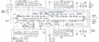
Electrical diagram of relay 23.3747 direction indicators and hazard warning lights.
Electrical diagram for switching on relay 23.3747 direction indicators and hazard warning lights.
Since 1985, the VAZ-2107 has been equipped with a relay-breaker 231.374, made on the basis of discrete elements. Both relay interrupters have the same technical characteristics. They ensure blinking of turn signal lamps with a frequency of 60-120 cycles per minute at a rated load of 92 W, ambient temperature from minus 20 to plus 50 degrees and a voltage of 10.8-15 Volts.
Main technical characteristics of the turn signal and hazard warning relay 231.3747.
— Rated voltage, V: 12 — Switched load in turn signal mode, number and power of lamps in W: 2х21+1х4 — Switched load in alarm mode, number and power of lamps in W: (2х21+1х4)х2 – Number and type control lamps: 1xAMN12-3-1 — Interrupt frequency, cycles per minute: 60-120 — Electrical connection design: pin block analogue 502606 OST 37.003.032, plug 6.3 — Overall dimensions: 34x47x85.5 — Weight, kg: 0 ,13
Unlike relay 23.3747, relay-interrupter 231.3747 does not have pin “5”, and the supply voltage is supplied only to pin “1”. Therefore, the brown wire connecting terminal “5” of the breaker relay to terminal “6” of the hazard warning switch was no longer needed.
So that, if necessary, you can install relay 23.3747 instead of breaker relay 231.3747, in the wiring harness block, terminal “1” of the breaker relay is connected to terminal “5”. Relay-breaker 231.3747 provides double flashing frequency of the warning lamp on the instrument panel in the event of one of the lamps burning out or an open circuit in its power supply.
On VAZ-2108, VAZ-2109, VAZ-2110 cars and their modifications, an electronic relay-breaker 491.3747 is used, in addition, on VAZ-2108, VAZ-2109 it is possible to install a relay-breaker 49.3747.
Main technical characteristics of the turn signal and hazard warning relay 491.3747.
— Rated voltage, V: 12 — Switched load in turn signal mode, number and power of lamps in W: 2х21+1х4 — Switched load in alarm mode, number and power of lamps in W: (2х21+1х4)х2 – Weight, kg : 0.05