The domestic auto industry is one of the most controversial topics raised by car enthusiasts. Yes, sales of the brainchild of Tolyatti engineers annually occupy leading positions in sales rankings, both on the new car market and on the secondary market. But everyone understands perfectly well that such indicators were achieved not thanks to the quality of the cars themselves, but because of the non-standard policy of the state itself in this regard, because of which foreign dealers, one by one, refuse to supply their new models to the Russian market.
As for quality, this has never been a strong point. Of course, its cars are in the lowest price segment, which means they belong to the lowest class of cars, designed exclusively for moving from one place to another on good road surfaces. VAZ completely excludes any kind of comfort - all the technologies used date back to the 70-80s of the last century.
However, this also has its advantages. For example, the structure of such cars has long been studied and is familiar not only to technicians at service stations, but also to many ordinary car enthusiasts. Another positive point is the simplicity of the design. Unlike foreign cars, especially those produced in Germany, all their spare parts can be easily found on free sale and separately, and not assembled and at a much higher price. This way, users do not have to rack their brains over the location of parts in the car, and, accordingly, over their installation during repairs or scheduled maintenance.
Starter, ignition, rear fog lamp relay
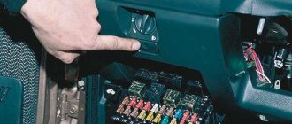
In order to carry out quick checks and repairs, the ignition system relay is installed under the front dashboard of the car, behind the hood release handle. It is located just below the central dashboard. The module is closed with a plastic plug, which must be opened slightly to test for functionality.
Starter, ignition, rear fog lamp relay
Next to the indicated relay, there is a similar one for the rear fog lights and the starter.
The main task of the relay when igniting is to reduce the applied load to the contacts. When the engine starts, the relay turns off some electrical circuits in the vehicle system. The system is used not only in injection, but also in carburetor engines.
In the event of a malfunction or malfunction in the ignition system, it is necessary to monitor the operation of the relay. For this purpose, open the box and carefully remove the desired element. It is attached using contacts to special grooves. The first thing to do is look at the oxidation of the contacts, if necessary, clean them with a soft cloth or treat them with a special liquid.
To check functionality, you need to use a regular multimeter. We connect to incoming connections and check the numbers. If there is no short circuit when current is applied, it means the element is not working. Replacement is carried out in a similar manner. It is necessary to use a standard element with the number of amperes indicated on the housing.
Changing the fuel pump yourself
If the fuel pump in the VAZ does not pump, and all of the above system components are normal, it is necessary to clean the filters, and, if necessary, completely replace the unit.
Before starting work, you must completely drain the fuel from the gas tank. To do everything with our own hands, we need a screwdriver and a set of keys. Replacing the VAZ 2114 fuel pump is carried out according to the following algorithm:
- We de-energize the car by removing the “-” terminal from the battery;
- We take out the rear row of passenger seats;
- Unscrew the plastic cap that covers the pump;
- Remove the power wires from the device and disconnect the fuel supply hoses;
- We dismantle the main fastenings of the fuel pump; for this we need the 7th key;
- Now you can remove the fuel pump on the VAZ 2114 and remove the device.
It must be removed carefully, since the float sensor for determining the fuel level is a very delicate structure that is easy to damage . Inspect the fuel pump - if necessary, clean or replace the strainer, however, it may be necessary to completely replace the unit.
Functions of VAZ-2115 fuses
A fuse in cars is a fuse-link that performs protective functions for current-carrying circuits. Such functions are aimed primarily at blocking either the entire circuit or an individual node from overloads. This is due to the fact that any vehicle is equipped with an on-board network with a whole set of circuits that conduct electric current. Their task is to ensure the uninterrupted functioning of the vehicle’s electrical equipment. Each section of the current-carrying circuit has its own specific fuse with the corresponding marking.
A standard automotive fuse is a small part, in a plastic body of which a filament of low-melting metal is placed, which acts as a conductor. If an overload occurs in a current-carrying circuit, this conductor thread will melt, which will cause a break in this circuit.
Due to this gap, a certain section of the on-board network will be de-energized and fail.
Image of VAZ-2115 fuse diagram
A fuse diagram for a vehicle is usually at hand for every car enthusiast. But how to understand all the icons and markings? This will be discussed in this article.
Functions of VAZ-2115 fuses
A fuse in cars is a fuse-link that performs protective functions for current-carrying circuits. Such functions are aimed primarily at blocking either the entire circuit or an individual node from overloads. This is due to the fact that any vehicle is equipped with an on-board network with a whole set of circuits that conduct electric current. Their task is to ensure the uninterrupted functioning of the vehicle’s electrical equipment. Each section of the current-carrying circuit has its own specific fuse with the corresponding marking.
A standard automotive fuse is a small part, in a plastic body of which a filament of low-melting metal is placed, which acts as a conductor. If an overload occurs in a current-carrying circuit, this conductor thread will melt, which will cause a break in this circuit.
Due to this gap, a certain section of the on-board network will be de-energized and fail.
How to distinguish fuses from each other on a diagram
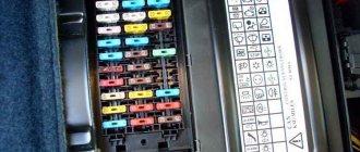
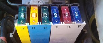
On the VAZ-2115, car fuses, in addition to special markings, are painted in different colors. This is done for convenience: each specific color corresponds to one of the calculated current values in accordance with GOST conditions:
- gray – 2 A;
- pink – 4 A;
- orange – 5 A;
- brown - 7.5 A;
- red – 10 A;
- blue or blue - 15 A;
- yellow – 20 A;
- white – 25 A;
- green – 30 A.
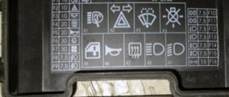
On the VAZ-2115 fuse diagram, 20 elements are marked, each of which corresponds to a marking with the English letter “F” and a digital designation. It is by the alphanumeric marking that you can find the desired fuse, which is responsible for a specific section of the conductive circuit:
- Rear fog lights – F1.
- Turn signal repeaters – F2.
- Car interior lighting – F3.
- Rear window heating – F4.
- Radiator fan, signal – F5.
- Electric windows – F6.
- Cigarette lighter, washer motor – F7.
- Front fog lights – F8-F9.
- Left-hand dimensions, front and rear license plate lighting, instrument panel lighting - F10.
- Right-hand dimensions – F11.
- Low beam headlights – F12-F13.
- Driving lights – F14-F15.
- Instrument panel indicator lamps – F16.
- Reserve safety elements for VAZ-2115 injector – F17-F20.
But in addition to the listed main safety elements, which are located in the mounting block of the engine compartment (on the left side under the windshield), the VAZ-2115 has several additional fuses. Additional safety elements are located in the vehicle interior itself - under the dashboard under the glove compartment on the passenger side. This arrangement of three additional fuses is due to their functional feature - they are responsible for the operation of the main engine systems. Such systems include:
- power supply for the gasoline pump – top location of safety elements;
- cooling fan, canister purge valve, speed sensor, crankshaft position and mass air flow sensor - middle location;
- central relay, ECU - bottom location.
As you can see, all of the above automotive parts perform important functions, so the safety elements for them must be protected from external influences, mechanical damage and negative environmental influences.
When there is a need to use a VAZ-2115 fuse diagram
Motorists use the diagram, which shows the placement of safety elements, to carry out the procedure for replacing those that have failed, that is, burned out. Car fuses blow out for several reasons:
- Short circuit in the current-carrying circuit.
- Overload in the entire on-board network.
- The use of additional electrical appliances that have greater power than the current values in the on-board network.
Short circuits can most often be observed when wires are broken, automotive electrical appliances are in a faulty condition, or moisture gets on their contacts.
As soon as the inactivity of a certain device (for example, a cigarette lighter) is noticed, the first thing to do is check its fuse. And to figure out where a specific safety element is located, you need to know the diagram and all the symbols on it.
Some useful tips
To ensure that the fuses in your VAZ-2115 last longer, and the failure of any of them does not take you by surprise, use the following tips:
- At least once a quarter, check the condition of the mounting block, its board and the protection elements installed in it. Do not allow moisture or dirt to get inside. If necessary, take care of its additional protection.
- When undergoing maintenance, ask an auto electrician to check the performance of the vehicle’s on-board network. If they deviate from the norm, take care of repairing the machine.
- Do not overload the vehicle's on-board network. Do not use electrical appliances that consume high current.
- Under no circumstances use homemade bugs instead of fuses. This can cause not only a short circuit, but also a fire in the machine.
- Carry a spare set of fuses with you. It costs 150-200 rubles, takes up virtually no space, and can help out at the right time.
Never do this in church! If you are not sure whether you are behaving correctly in church or not, then you are probably not acting as you should. Here's a list of terrible ones.
What does your nose shape say about your personality? Many experts believe that you can tell a lot about a person's personality by looking at their nose.
Therefore, when you first meet, pay attention to the stranger’s nose
11 Weird Signs That You're Good in Bed Do you also want to believe that you please your romantic partner in bed? At least you don't want to blush and apologize.
15 Cancer Symptoms Women Most Often Ignore Many signs of cancer are similar to symptoms of other diseases or conditions, which is why they are often ignored.
Pay attention to your body. If you notice
7 Body Parts You Shouldn't Touch with Your Hands Think of your body as a temple: you can use it, but there are some sacred places that you shouldn't touch with your hands. Research showing.
10 charming celebrity children who look completely different today Time flies, and one day little celebrities become adults who are no longer recognizable. Pretty boys and girls turn into...
Pressure level
In order to get most of the picture of what is happening, it is enough to measure the pressure in the fuel rail. For this, it is necessary to use a pressure gauge that has a small measurement range (preferably up to 7 atmospheres), since devices with a large range can produce significant inaccuracies.
Rail pressure measurement
Under the hood of the fourteenth there is a pressure fitting; unscrew its cap and connect the pressure gauge to it. Normal indicators should be as follows:
- When the engine is idling – 2.5 kPa;
- At the moment of ignition - 3 kPa;
- With a pinched drain hose – 7 kPa;
- When gaining speed - 2.5-3 kPa.
If the pressure gauge needle does not move when the ignition is turned on, then the gasoline pressure regulator is most likely broken. When there is no change as the speed increases, the fuel pump itself has failed, but if the needle moves very slowly, which indicates that the pump is pumping, but poorly, the fuel pump screen is clogged.
Location and electrical diagram
The fuse is turned on simultaneously with the device for which it is responsible. As mentioned above, if the optimal voltage parameters in the circuit are exceeded, the electrical circuit breaks. By the way, in total, power supply elements in vehicles operate for one hundred hours.
VAZ 2114 car
VAZ 2114 vehicles with an injection engine use a single-wire wiring system, which is typical for most cars that exist today. Each, without exception, energy consumer connected to the power supply has its own fuse, which, as a result of an increase in voltage or a short circuit, immediately opens the entire circuit. This is done to prevent overheating of the wiring, and therefore a potential fire.
However, not all devices and instruments of the vehicle are connected to the power supply. Some components of domestic cars require high voltage, which means they cannot be protected by fusible power supply components. For example, these include the circuit of the ignition coil, engine start, and battery. As a rule, the wiring of such components has a much larger cross-section and is equipped with a reliable layer of insulation.
Location of the fusible device block of the VAZ 2114 car
Therefore, take into account the fact that before disassembling the headlights, radio, ventilation system or anything else, you need to make sure that the power supply element itself responsible for this device has not failed. We invite you to familiarize yourself with the diagram and location of the power supply elements and relays in the VAZ 2114 car. The power supply itself is located in the engine compartment, on the left side in the direction of travel of the car. Opening the hood, under the wipers you will see a power supply unit, which is usually painted black. In order to remove the cover, you need to disconnect the two latches on the sides of the power supply.
Removing the cover of the box, you will see a device on which nine relays and twenty fuses are located. On the inside of the protective cover there is a diagram identifying the purpose of each power supply device, including the relay. Below we will look at the electrical circuit and the purpose of each individual power supply component.
Electrical diagram of device components
| Number | Purpose |
| K1 | Ensures the functionality of the headlight washer wipers. |
| K2 | Responsible for the operation of direction lamps, as well as light signaling. |
| K3 | Windshield cleaner. |
| K4 | Ensures the functioning of the light bulb, which is responsible for the operation of other lamps. |
| K5 | This relay is responsible for the operation of the power windows. |
| K6 | The purpose of this relay is to ensure the operation of the steering horn. |
| K7 | Rear window heating device. |
| K8 and K9 | These relays are responsible for the operation of high and low beam lamps. |
We will also consider the purpose of power supply elements responsible for lighting, operation of the stove, cigarette lighter, fuel pump, etc.
Table of assignment of devices of the mounting block of the VAZ 2114 car
Fuse Location
For ease of maintenance, most fuses are installed in a special mounting block, and here the VAZ-2115 injector is no exception. You just need to know that this model has two of them installed.
The first one in the VAZ-2115 (equipped with an 8-valve engine) is located directly in the cabin, under the dashboard, at the steering wheel. The other one is installed near the engine, that is, under the hood, next to the left glass.
Any of the fuses located in the mounting block has its own specific designation, based on this, it is not difficult to find out which circuit it is responsible for.
So the fuse is marked:
- K1 – protects the relay that turns on the headlight cleaning from overvoltage;
- K2 – for emergency signaling and switching of turn signals;
- K3 – power supply for the “janitors”;
- K4 – lighting;
- K5 – window regulators;
- K6 – horn;
- K7 – rear window heating element;
- K8 – high beam headlights;
- K9 – close;
Below are fuses with fuse links, which are designated F and have a serial number. Each of them is designed for a specific current.
The unit installed in the cabin is slightly different from the one described above. It contains, in particular:
- relays (3 pieces);
- ECU;
- fuses (3).
Each of the latter is designed to protect a specific circuit from overvoltage and short circuit.
Down up:
- on-board computer power supply (7.5 A);
- radiator cooling fan, and in addition an adsorber valve, mass air flow sensors, DC and DC sensors (7.5A);
- fuel pump (15 A).
As noted earlier, this block also contains three relays. Down up:
- Basics.
- Radiator fan control.
- Responsible for the operation of the fuel pump.
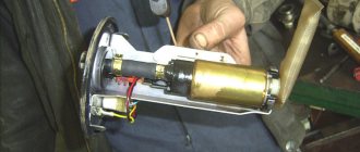
Operating principle and design features
The VAZ 2114 fuel pump is located inside the car’s gas tank, which is why access to it can be problematic if you don’t know which side to approach. To free up access to the fuel pump, you need to remove the rear seat from the fourteenth, under which you will find a rectangular hatch hiding access to the fuel module.
Just fold back the back seat and see for yourself
In addition to the pump itself, the VAZ 2114 fuel module includes:
- A float sensor that monitors the fuel level in the gas tank;
- Chamber for fuel intake;
- Mesh filter for coarse cleaning.
The gasoline pump has a built-in electric motor, which pumps up the pressure of the pumped fuel. The motor itself is powered from the vehicle's on-board network. The VAZ 2114 gasoline pump is located so that even with a minimum level of fuel in the tank, it is constantly washed with gasoline, as this is necessary for normal cooling of the unit, which gets very hot during operation.
The main working element of a gasoline pump is a membrane, which during operation performs reciprocating movements. During normal operation, when the device is fully operational, the following pressure levels must be maintained in the fuel rail:
- For 1.5 l engine. – from 285 to 326 kPa;
- For 1.6 liter engine. – from 375 to 390 kPa.
As evidenced by reviews from owners of fourteenth VAZs, in practice BOSCH pumps have proven themselves to be the best.
Unlike domestically produced units, they cost almost 20-30% more, but at the same time they have an order of magnitude better build quality and reliability. The estimated cost of the fuel module for a 1.5 liter engine of the fourteenth is 2.5 thousand rubles, for 1.6 liters. – 2.6 thousand
However, rational savings are possible here - in most cases it makes sense to purchase a fuel pump separately, rather than the entire module, since, as a rule, the pump itself “dies”, and the remaining parts of the module remain in working order. Its cost, if taken separately, is 1-1.5 tr.
Fuses and relays VAZ 2114, 2115, 2113
Today, every car, regardless of type, is equipped with special protection for all electrical systems. This protection is called a fuse. They are installed so that in the event of a short circuit or malfunction, the system can turn off via a fuse, thereby protecting itself from breakdown. Fuses are used for every electrical circuit, from a small light bulb to an engine's ignition system. More important engine systems are equipped with special relays, they protect various pumps, electric motors and other powerful sources of electricity consumption.
The fuse is a small structure consisting of a plastic casing with a fusible element inside. If a short circuit occurs, the thin contact melts under the influence of current, which interrupts the electric current. The simplest electrical fuse is a thin copper wire inserted into a circuit. If the upper limit of the supplied current increases, the contact begins to melt and interrupts the flow of electricity. Here there is a description of all fuses and relays for VAZ 2113, 2114, 2115 models of injection and carburetor types, old and new models.
Why does the fuel pump fuse blow? List of reasons
Having installed a new element, the car drives several tens of meters and stops again. At the same time, during these meters traveled, the car manages to shake and shake quite a bit.
The very name “fuse” indicates that this small element protects a more expensive device from failure. If the fuse blows, then the problem may lie in something more serious. Therefore, you should not insert another element instead of the desired one. The fuse consists of thin plates made of a certain material and they are of a fixed thickness.
A fusible element is soldered between the set of plates, which opens the circuit when overloaded. This entire structure is enclosed in a polymer mandrel.
The main reason for a blown fuse
Why does the fuel pump fuse blow?
, it is necessary to disassemble starting with the electrical wiring. It is the vehicle wiring that often causes the fusible element to fail. Overloading the wiring can short circuit a specific device, and in this case it is the fuel pump.
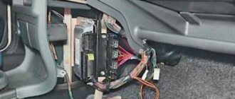
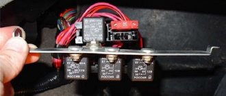
Explanation of the additional fuse and relay block
To turn on the main systems of any car, the manufacturer has designed the installation of auxiliary fuses. As a rule, they are located in the center console area. Each auxiliary module consists of several important relays and fuses.
In this particular case, the box is located to the left of the glove compartment, behind the side trim of the center console. To quickly access the box, you need to remove part of the plastic protection. The protection is attached to Phillips bolts, so you need to prepare the appropriate screwdriver.
Table 3. Explanation of the additional fuse and relay block
There are also options for other decryptions.
Explanation of the additional fuse and relay block
Relay:
Fuse:
f2 - main relay;
f3 - ECU (electronic control unit).
Relays that control the supply of current are present in the design of many vehicles. They are designed to perform a very important function - they turn on and off important electrical devices and mechanical systems of the vehicle. In simple terms, this is a device for supplying current to a required element.
Checking the fuse
First, let's figure out where the VAZ 2114 fuel pump fuse is located: you can find it under the hood, on the windshield side. There is a drawer on the electronic control unit that needs to be opened. In the box we need a fuse that says Fuel Pump 15A above it. If the fuse for the VAZ 2114 fuel pump is blown, you need to install a new one.
The fuse blows due to incorrectly connected alarm contacts or the anti-theft system.
Fuel pump fuse VAZ 2115
The pump relay is the lowest. Its fuse is also at the very bottom. When you turn the key, the relay turns on for 5 seconds in order to pump up pressure in the system and turns off. After the engine starts, control of the pump passes to the computer.
The mass of the pump (and fuel level sensor) is attached to the stud securing the handbrake to the body under the carpet. To get to it you need to remove the vestibule between the passenger and driver seats. There are 3 wires going to the fuel pump. first +, second minus, third fuel level sensor.
Where is
If we describe them from top to bottom, we get the following:
1. The fuse that controls the fuel pump. Its current strength is 15 amperes.
A fuse is a small element whose task in the design of electrical circuits is to melt in the event of an overload. The device melts and the current-carrying circuit opens.
Using the example of a solution from the popular VAZ Priora model, we can superficially examine the design and operating principle of the fuse. The device is small, the outer casing is made of plexiglass.
There is a conductive element inside. Such an element is based on several plates, which are made of different materials. Between these plates there is a special low-melting material. Electricity passes through this material, which allows the fuse to be an integral part of the electrical power circuit of the fuel pump. Fuses have a special marking in the form of the letter F. This designation indicates that the fuse element belongs to a circuit whose power is not large. To calculate the current that certain devices are designed for, you need to divide the power by 220. The result will be a figure in amperes.
If the fuse is blown, then such a malfunction is often caused by the following reasons:
— short circuit in the electrical circuit;
— failure of the fuel pump relay;
- low quality of the fuse itself;
In other words, more often the fuel pump fuse blows due to faults in the electrical circuits or as a result of failure of the components of the pump power circuit. Note that situations also arise when the fuel pump fuse burns on its own, but this phenomenon occurs much less frequently with high-quality elements.
How to identify a malfunction
The fuel pump relay turns on the fuel pump and delivers fuel to the injectors. The safety relay is activated when the engine is not running and the ignition is on (the control unit does not receive speed signals). This relay is switched off in the control unit via a safety switch and interrupts the power supply to the pump. For example, in the event of an accident, gasoline cannot flow into the engine. Checking the fuel pump is a job most likely reserved for service centers. In this regard, to find errors, we will limit ourselves to the following points:
— disconnect the fuel supply line at the distributor, while preparing a rag for spilled gasoline;
— even when the engine is turned off, a certain amount of gasoline may come out, since the system is under pressure;
— turn on the ignition for a short time without turning on the starter;
— if the pump does not start working, check the fuse or safety relay again;
— if fuel does not flow, check the pump relay;
— if the relays are working properly, the fuel pump should start working;
- otherwise, remove the cover under the rear seat and carefully tap the pump housing with a small hammer - sometimes it helps;
— check the correct connection of the wires to the fuel pump;
- if the pump does not work, check the voltage using a diode bridge (a conventional test lamp can damage the control unit). Don't forget to turn on the ignition first;
- if the voltage is normal, it means the pump is damaged or there is an open circuit. The pump should be replaced with a new one.
The fuel pump relay does not turn on.
If the fuel pump does not work, then first of all you need to check the attraction of the main relay and the fuel pump relay. If the main relay does not click, then it is necessary to check its switching circuit and its serviceability. How to do this is described in the article the main relay does not turn on,
In the case when the main relay turns on, but the fuel pump relay does not, it is necessary to check the power at pins 85 and 86. When using a test lamp, its current consumption should not exceed 0.25A, otherwise damage to the controller may occur. If the control lamp does not light up on any terminal, then the relay is not receiving power. This may be caused by a blown fuse or a broken power cord.
In the case when the lamp burns brightly on one terminal, and at half-glow on the second, and the relay may be activated, you should remove the relay from the socket and connect terminals 85 and 86 with a test lamp. When the ignition is turned on, the control lamp should light up and go out after approximately 20 - 30 seconds. If the lamp lights up and there is poor contact in the connection between the block and the fuel pump relay. If the lamp does not light up, there may be a break in the wire connecting the relay to the controller or the controller itself may be faulty.
Decoding the plugs of the mounting block of fuses VAZ 2114, 2113, 2115 model 2114-3722.010
| Table for decoding the terminals of the VAZ 2114, 2113, 2115 fuse mounting block | |||
| Plug connector designation | Terminal number | Wire color | Device name |
| Ш1 | 1 | B | window lifters |
| 2 | G | ignition switch (cl. 15/2) | |
| 3 | GP | ignition switch (terminal 15) | |
| 4 | ZhG | heater motor switch | |
| 5 | R | ignition switch (cl. 30/1) | |
| 6 | KR | ignition switch (terminal 30) | |
| 7 | door lock | ||
| 8 | P | ignition switch (terminal 50) | |
| Ш2 | 1 | BG | rear window wiper switch |
| 2 | G | Turn signal switch (right) | |
| 3 | RP | brake light switch | |
| 4 | B | lamp continuity indicator | |
| 5 | IF | hazard warning switch | |
| 6 | GB | left front door | |
| 7 | ABOUT | rear fog light switch | |
| 8 | 34 | high beam warning lamp | |
| 9 | -/td> | ||
| 10 | 04 | rear fog light switch | |
| 11 | midrange | fuel reserve warning lamp | |
| 12 | pch | fuel level warning lamp | |
| 13 | Warhead | interior lamp | |
| 14 | kg | hand brake warning lamp | |
| 15 | hh | Turn signal switch (left) | |
| 16 | electric motor for headlight cleaner | ||
| 17 | — | ||
| Ш3 | 1 | and | speed sensor |
| 2 | emergency | hazard warning switch | |
| 3 | gp | direction indicator switch | |
| 4 | Sat | oil level warning lamp | |
| 5 | h | weight | |
| 6 | RB | washer fluid level warning lamp | |
| 7 | ro | brake lining wear warning lamp | |
| 8 | 3v | headlight switch | |
| 9 | zhz | windshield wiper switch | |
| 10 | pg | portable lamp connection socket | |
| 11 | O | ignition switch (terminal 15) | |
| 12 | RF | rear window washer switch | |
| 13 | |||
| 14 | and | fog light warning lamp | |
| 15 | |||
| 16 | sg | oil pressure indicator | |
| 17 | |||
| 18 | R | wiper switch | |
| 19 | with | wiper switch | |
| 20 | With | wiper switch | |
| 21 | about | rear fog light switch | |
| Ш4 | 1 | salary | On and indicator lamp for heated rear window |
| 2 | GB | headlight switch (high beam) | |
| 3 | O | wiper | |
| 4 | warhead | outdoor lighting switch | |
| 5 | To | Instrument lighting rheostat | |
| 6 | R | battery | |
| 7 | bw | windshield wiper and washer switch | |
| 8 | O | block Ш4 of the mounting block terminal 3 | |
| 9 | sch | horn switch | |
| 10 | bp | brake light switch | |
| 11 | R | battery | |
| 12 | joint venture | headlight switch (low beam) | |
| 13 | warning light | ||
| 14 | — | ||
| 15 | — | ||
| 16 | rg | brake fluid level warning lamp | |
| 17 | zb | coolant temperature gauge | |
| 18 | kb | battery charge indicator lamp | |
| 19 | zhch | fog light switch | |
| 20 | rz | coolant level warning lamp | |
| 21 | and | tachometer | |
| Ш5 | 1 | 3 | high beam (right) |
| 2 | zch | high beam (left) | |
| 3 | sch | low beam (left) | |
| 4 | P | starter (cl. 50) | |
| 5 | pb | electric radiator cooling fan | |
| 6 | With | low beam (right) | |
| Ш6 | 1 | — | |
| 2 | 3 | reverse light switch | |
| 3 | hh | Turn signal (left front) | |
| 4 | |||
| 5 | — | ||
| 6 | — | ||
| 7 | — | ||
| 8 | zhch | side light (right front) | |
| 9 | warhead | electric fan thermostat | |
| 10 | zhch | side light (left front) | |
| 11 | G | Turn signal (right front) | |
| 12 | O | reverse light switch | |
| 13 | rg | brake fluid level sensor | |
| Ш7 | 1 | — | |
| 2 | zhg | electric motor for headlight cleaner | |
| 3 | b | electric motor for headlight cleaner | |
| 4 | — | ||
| 5 | Sat | oil level sensor | |
| 6 | sch | sound signals | |
| 7 | With | speed sensor | |
| 8 | zb | coolant temperature sensor | |
| 9 | kb | generator (cl. 61) | |
| 10 | R | windshield washer pump | |
| 11 | warhead | engine compartment lamp switch | |
| 12 | RB | washer fluid level sensor | |
| 13 | RF | brake linings | |
| 14 | |||
| 15 | kp | tachometer | |
| 16 | rz | coolant level sensor | |
| 17 | reinforced concrete | fog light relay | |
| Ш8 | 1 | zhl | fog light relay |
| 2 | zhch | fog lamp (left) | |
| 3 | and | fog lamp (right) | |
| 4 | gp | ignition coil | |
| 5 | R | generator (cl. 30) | |
| 6 | R | generator (cl. 30) | |
| 7 | |||
| 8 | RF | fog light relay | |
| Ш9 | 1 | RF | electric motor rear window wiper |
| 2 | G | Turn signal (right rear) | |
| 3 | bg | electric motor rear window wiper | |
| 4 | very good | rear fog lights | |
| 5 | sch | back door | |
| 6 | pch | front right door | |
| 7 | warhead | interior lamp | |
| 8 | kg | handbrake sensor | |
| 9 | warhead | open door alarm buttons | |
| 10 | rear window heating elements | ||
| 11 | With | license plate light | |
| 12 | GB | front left door | |
| 13 | b | interior lamp | |
| 14 | P | brake lights | |
| 15 | and | side light (right rear) | |
| 16 | h | reversing light | |
| 17 | zhch | side light (left rear) | |
| 18 | zhch | rear window cleaner | |
| 19 | O | rear window heating elements | |
| Ш11 | 1 | and | pump |
| 2 | RF | rear window washer valve | |
| 3 | |||
| 4 | and- | pump | |
| 5 | warhead | engine compartment lamp | |
| 6 | |||
| 7 | |||
| 8 | CC | engine compartment lamp | |
| 9 | b | electric windshield wiper motor | |
| 10 | O | windshield wiper motor | |
| 11 | |||
| 12 | with | emergency oil pressure sensor | |
| 13 | |||
| 14 | R | windshield washer valve | |
| 15 | with | electric wiper motor | |
| 16 | With | electric windshield wiper motor | |
| 17 | reinforced concrete | electric windshield wiper motor | |
| 18 | |||
| 19 |
Wire colors:
- B - white;
- G - blue;
- F - yellow,
- 3 - green,
- K - brown;
- O - orange;
- P - red;
- P - pink;
- C - gray,
- H - black.
Pinout BN VAZ 2108, 2109, 21099
Where is the fuel pump fuse for the VAZ 2115 injector where is it located?
The fuel pump activation relay (2) is shown by an arrow.
1 — nozzles; 2 — spark plugs; 3 — ignition module; 4 — diagnostic block; 5 - controller; 6 — block connected to the instrument panel harness; 7 - main relay; 8 - main relay fuse; 9 — electric fan relay; 10 — controller power supply fuse; 11- electric fuel pump relay; 12 — fuel pump power circuit fuse; 13 — mass air flow sensor; 14 — throttle position sensor; 15 — coolant temperature sensor; 16 — idle speed regulator; 17 — knock sensor; 18 — crankshaft position sensor; 19- oxygen sensor; 20- APS control unit; 21 — APS status indicator; 22 — speed sensor; 23 — electric fuel pump with fuel level sensor; 24 — solenoid valve for purge of the adsorber; 25 — block connected to the ignition system harness; 26 — instrument cluster; 27 — ignition relay; 28 — ignition switch; 29 — mounting block; 30 — electric fan of the cooling system;
A - to terminal “B+” of the generator; B - block connected to block K of the ignition system harness; C - block connected to block L of the ignition system harness; D - wire connected to the interior lamp switch; E - wire connected to the white and black wires disconnected from the interior lamp switch; F - to the “+” terminal of the battery; G1, G2 - grounding points; K - block connected to block B of the front harness; L — block connected to block C of the front harness.
On “nines” with a mechanical fuel pump, the most common malfunction is wear of the fuel pump diaphragm, as a result of which gasoline will leak through the drainage hole in the housing when it operates. The second reason for the failure of such a fuel pump is wear of the pusher, which transmits force from the camshaft cam to the fuel pump drive lever.
Checking wiring contacts
If the fuel pump does not work, do not rush to change it - perhaps the problem is in poor-quality wiring. There are 3 wires connected to the pump: to the gasoline level sensor, and positive and negative to power the motor.
No special tools are required to check the wiring - a regular 12-volt light bulb is enough. We connect the light bulb to the negative and positive wires of the pump, and turn on the car’s ignition - if the light blinks, then everything is fine with the wiring.
When you have determined that the external wiring of the fuel pump is normal, you need to move on to checking the motor. This is done with the same light bulb, the wires of which are connected to the external terminals of the motor. If the light comes on when you turn on the ignition, then you need to change the motor.
The cigarette lighter does not work on the VAZ 2115
In modern car operating conditions, drivers in most cases use the VAZ-2115 cigarette lighter socket not for its intended purpose, but as an outlet for connecting additional devices to it, as a power source, which are now sold in abundance in Russian automotive spare parts stores . But those drivers who do not think about the consequences of such actions often pay for it with repairs related to replacing the cigarette lighter socket or even repairing the mounting block.
The main reason for the failure of the cigarette lighter is that the plugs of additional devices, especially imported ones, through which they receive power, although slightly, still differ in diameter and the length of the protrusion of the central contact, to which the positive must be supplied from the current source.
If the central contact of the plug is slightly short, then when it is installed in the cigarette lighter socket, the antennae attached to the positive contact of the cigarette lighter socket move apart.
This can lead to these antennae touching the body of the cigarette lighter socket, to which the wire going to the ground of the car is connected.
As a result, a short circuit occurs and the fuse protecting this electrical circuit blows.
To replace a blown fuse, you will have to open the cover of the mounting block, which has symbols that help the driver quickly find the fuse he needs.
But the problem is that there is no cigarette lighter symbol on it and the driver will have to look for a diagram of the location of the fuses in the mounting block, from which it will become clear that this electrical circuit is protected by fuse F7 (30A).
If, when checking this fuse, it turns out that it is safe and sound, then the driver will need to look at another fuse F4 (20A), which will probably be blown. This is what will have to be replaced. But why F4 burned out and not F7, you need to ask automotive electricians.
The fuel pump does not work, the relay turns on.
Checking relay power.
In the case when the fuel pump relay turns on when the ignition is turned on, but the pump itself does not work, you need to check the power at terminal 87 of the fuel pump relay. To do this, touch terminal 87 of the relay socket with the output of the control lamp connected to the vehicle ground, and the lamp should light up. If the lamp does not light, it means the fuse has blown or there is a break in the wire.
If there is power at terminal 87, you should remove the relay from the socket, and instead place a jumper between pins 87 and 30. In this case, if the pump and connecting wires are working properly, the pump should start working and if this happens, the relay should be changed. If the pump does not start working, then, without removing the jumper, you need to touch the power wire on the fuel pump with a test lamp connected to the vehicle ground.
Checking the fuel pump power circuit.
If a submersible pump is installed on the car as part of the fuel module, you need to remove the connecting connector and touch one of the thick wires. When you touch one of them, the indicator lamp should light up. If the lamp does not light up on any of the wires, then it is necessary to eliminate the break in the wire from the fuel pump relay to the module connector or the pump itself, if the pump is of a remote type. One of the reasons for the break may be the anti-theft blocking of an installed non-standard alarm system.
In the case when the test lamp lights up on one of the thick wires of the connector or one of the terminals of the remote pump, you need to connect these terminals with a test lamp to each other. In this case, the control lamp should light up. If the lamp does not light, it is necessary to eliminate a break or poor contact in the wire connecting the pump to the vehicle ground.
If, when checking the wires and relay for turning on the fuel pump, no malfunction is detected, the electric motor of the fuel pump or its connection to the module connector is faulty. It is not difficult to find the cause by removing the fuel pump module from the tank. If there is poor contact with the connector, melting of the plugs will be visible. If melting is not noticed, then to check the pump itself, you can connect it to the battery. It should be taken into account that operating a submersible pump without liquid will damage the pump. A faulty pump should be replaced.
Hello to all subscribers! One of the common situations that happens, usually unexpectedly, is that the usual buzzing of the electric fuel pump in the rear of the car is absent when the ignition is turned on. As a result, the car engine refuses to start. I present an algorithm of actions if such a disaster suddenly happens. To begin with: photo 1 shows a fragment of the electrical circuit of the fuel pump.