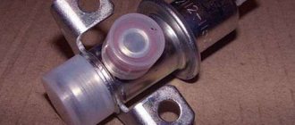
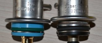
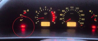
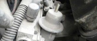
On VAZ-2110 vehicles, the fuel pressure regulator ensures the functioning of the fuel injection system in normal mode. With its help, the optimal pressure value necessary for the gasoline to be in a state of fog is maintained in the fuel rail. Due to the pressure, which is higher than atmospheric, the air-fuel mixture is injected into the combustion chambers. If the regulator fails, the entire injection system does not work correctly and serious problems in the functioning of the engine are possible.
How regulators work
The fuel rail is necessary to mix gasoline vapors and clean air. It maintains pressure at 2.9-3.3 kgf/sq. cm due to the pressure regulator. For injection, injectors with a solenoid valve are used. A regulator is connected to them, which is a valve made of a membrane. The device inlet is from the ramp side, the outlet is on the fuel drain line. A tube from the intake manifold is connected to the VAZ-2110 fuel pressure regulator.
The pressure is adjusted using a spring; its rigidity is selected so that it compresses only with a certain force. If the pressure of the fuel mixture in the rail exceeds 3.3 kgf/sq. cm, then the spring compresses, the valve opens and the excess is released into the return line. When the pressure reaches 2.9 kgf/sq. see the valve closes.
Pressure regulators VAZ 2110 - design and operation
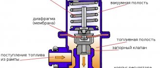
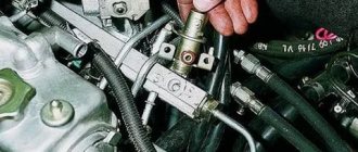
A fuel pressure regulator (FPR) is needed to maintain gasoline pressure in the fuel system at a constant certain level, regardless of engine operation. It is installed in the injector rail and is a diaphragm valve connected to the fuel supply channel to the injectors, the drain line and the air tube supplied from the intake manifold.
The RTD valve is affected by fuel pressure, on the one hand, and, on the other, by air pressure in the tube and spring force, adjusted to certain operating parameters in the system. When the engine is running, a serviceable RTD maintains the following indicators in the system: 2.9–3.3 kgf/cm 2 (284–325 kPa).
Types of faults
Among the most common device breakdowns are the following:
- The valve does not hold pressure - gasoline circulates freely throughout the entire line, including the return line. In this case, the pressure in the ramp decreases significantly, and it may not be constant. When you increase the engine speed, it begins to stall - there is not enough pressure to carry out normal injection. The amount of gasoline inside the ramp is very small. There is a noticeable decrease in power; it takes longer to start the engine than during normal operation. The electric fuel pump will run longer than usual.
- The valve does not work at all (does not open at maximum pressure) - the excess does not go into the tank. The pressure in the fuel rail is too high, significant excess consumption of gasoline occurs, and the cylinders are flooded. This malfunction of the fuel pressure regulator on the VAZ-2110 cannot be eliminated, so you only need to change the device completely.
How to check the pressure in a system with no return?
The VAZ-2110 with a volume of 1.6 liters has constant pressure indicators in the ramp, which, as a rule, vary around 3.6-4 bars.
In addition to the most commonly used measurement methods described above, there are several more unusual solutions:
a) Here we return again to the hose with a pressure gauge, the diameter of which should be 7.5-8 millimeters. Measurements should be taken at the outlet of the fuel pump module. Five to seven atmospheres are normal test results.
b) Remember how the return line is closed on motors with a drain frame. It is recommended to turn off the engine directly at the gasoline pump. Next, you will need to remove the double hose and insert a plug (“The nipple” from an old fuel filter may also be suitable for this task). Now you need to pull a single tube onto the pump fitting. The measurements themselves must be made at the fuel rail.
How to clear a blockage if the fuel supply line is clogged.
One of the reasons for low pressure may be a malfunction of the sensor that regulates the fuel pressure before injection. Low pressure may also be a consequence of a clogged fuel line. By taking proper measurements, you can accurately determine the cause of the malfunction. First, you should check the pressure of the pump and line, then measure the pressure in the ramp. All of the above will help determine the exact cause.
How to clear clogged fuel injectors.
There are several signs to tell you that your fuel injectors are dirty. Let's start in order.
- Difficulty starting the engine.
- Unstable engine operation.
- Dips in the timing of sharp pressure on the gas pedal.
- Loss of power and deterioration in acceleration dynamics.
- Increased toxicity of treated gases.
- Increased fuel consumption.
- The occurrence of detonation.
- Popping sounds in the exhaust system.
- Misfires.
To solve this problem you need to clean the fuel injectors.
Clogged valve. How to identify and fix the problem.
When the valve is clogged, fuel is difficult to pass through, and because of this, it begins to leak everywhere. A significantly increased fuel consumption indicates that it is time to change the regulator, since it is the leading component. Fuel stops being supplied to the supply system if the valve becomes completely clogged.
What to do if the valve is stuck.
Uneven pressure in the system is usually the result of a stuck valve. Because of this, the vehicle's movement may be uneven. The car may also jerk or stall.
Signs of breakdown
To independently identify a breakdown of the device, take a closer look at the operation of the engine. Typically the fault appears like this:
- The engine's operation is unstable, it shakes, and misfires are felt in the cylinders.
- When idling, the engine stalls.
- Acceleration is weak - throttle response is low, driving is difficult.
- There is a noticeable decrease in engine power; even at minimum load it feels “heavy”.
- The crankshaft rotates either at a low or high frequency. Sometimes the rotation speed varies over a wide range.
- Significant increase in gasoline consumption.
- Jerks and dips during uniform movement.
- Sometimes the breakdown manifests itself as difficulty starting the engine.
- Among the signs of a malfunction of the fuel pressure regulator on the VAZ-2110, one can highlight a significant excess of CH and CO content in the exhaust.
The last breakdown is detected only when diagnosing the engine using a gas analyzer.
What to expect from a non-working check valve
Nothing good. At the very least it is a difficult start. Airing of the diesel power system is a rather problematic breakdown on the road. Injection power systems also do not like air in the system. Troubles begin when we turn off the engine, and the fuel, which must wait for the next start (working pressure must be maintained in the system), goes into the tank along the working line, and air takes its place. Now, in order to start the engine, it is necessary to normalize the pressure in the system and supply fuel to the injectors. To do this, you need to turn the engine with the starter for 40-50 seconds, so starting with half a turn is out of the question.
Regulator diagnostics
To carry out diagnostics you will need the following tool:
- pressure gauge (the one used to check tire pressure is suitable);
- open-end wrench 24;
- hexagons (only #5 is required).
And now about how to check the fuel pressure regulator on a VAZ-2110:
- Remove the plug from the fitting located at the end of the fuel rail.
- The spool can be unscrewed from the fitting using a cap (metal) for the wheel tires.
- Using a hose of suitable diameter, connect the pressure gauge to this fitting. Be sure to secure the edges with clamps - there is high pressure inside and it can break.
- Start the engine and measure the pressure.
- Disconnect the vacuum tube from the regulator and repeat the measurement.
When the vacuum tube is disconnected, the pressure should increase by 0.2-0.7 kgf/sq. see. If this does not happen, a complete replacement of the device is required.
Where is the check valve located?
You need to know the enemy by sight, so let's start by looking for a check valve in car power systems. The valve can be installed in the fuel pump housing of injection engines, on the fuel rail, or simply in the fuel line between the gas tank and the fuel injectors. On diesel engines, it is installed between the low-pressure hand pump and the injection pump so that the pressure at the inlet to the high-pressure pump is always stable. This system is installed on all KAMAZ 740, Tatra, MAN and Renault Magnum engines. In diesel engines with a fuel preheating system, a check valve is necessarily installed in front of the heating system, as in Magirus trucks, the same KAMAZ of the Arctic version, and many others.
The check valve for injection engines may be located on the fuel frame
In domestically produced passenger cars with injectors, the 16-valve VAZ 2110, 2114, the check valve is installed in the fuel pump and on the fuel rail, similar to the diesel system. In old carburetor cars, VAZ 2108, 2109, classic rear-wheel drive models, the role of a check valve is played by the fuel pump itself, which is installed on the cylinder block and does not allow fuel to flow back into the tank, thanks to the sealed outlet valve of the fuel pump. When the valve loses its tightness, the gasoline goes completely into the tank, and the engine can only be started with manual pumping.
Prudent owners independently installed return valves to make starting the engine easier. On old models of the Opel Cadet, Mazda 323, when starting was difficult, it was enough to buy and install a check valve into the power system closer to the carburetor or mono-injector, and the fuel stopped flowing through the working line into the tank, and the start became normal even at sub-zero temperatures.
How to replace the regulator?
To replace the regulator, you will need to do the following:
- Stop the engine. Do not perform any actions while the engine is running.
- Relieve pressure in the rail. Simply unscrew the spool valve from the fitting and wait until the pressure equalizes.
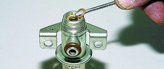
- Unscrew the nut that secures the return line pipe to the fuel pressure regulator on the VAZ-2110.
- Unscrew the bolts securing the device body to the fuel rail.
- Remove the regulator fitting from the hole.
- Disconnect the tube from the body.
- Remove the regulator completely.
All steps to install a new device occur in reverse order. Be sure to soak all rubber O-rings in gasoline before installation. All rubber elements that are damaged or have lost their original appearance must be replaced with new ones. Poor quality gaskets and seals will lead to the entire fuel supply system not working properly.
Fuel system diagram for VAZ-2112 injector 16 valves: photo
The fuel system is one of the most important components in any car. After all, without it it is simply impossible to imagine the full operation of the vehicle. And so that you can imagine what the fuel system on your VAZ-2112 consists of, below we will present you with its detailed diagram, with a detailed description of each of the main elements.
Detailed diagram of the fuel system
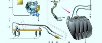
Detailed diagram of the fuel system.
1 — nozzles; 2 — fitting plug for monitoring fuel pressure; 3 — injector ramp; 4 — bracket for fastening fuel pipes; 5 — fuel pressure regulator; 6 — adsorber with solenoid valve; 7 — hose for suction of gasoline vapors from the adsorber; 8 — throttle assembly; 9 - two-way valve; 10 - gravity valve; 11 - safety valve; 12 - separator; 13 — separator hose; 14 — fuel tank plug; 15 - filling pipe; 16 — filling pipe hose; 17 — fuel filter; 18 — fuel tank; 19 — electric fuel pump; 20 — fuel drain line; 21 - fuel supply line.
Below we will look at the main elements of the fuel system separately.
Fuel tank
Dismantled VAZ-2112 gas tank.
The filled gasoline is supplied from the tank, which is located in the rear of the car, in the area where the sofa is located. The tank is made of steel and assembled by welding two stamped parts. Gasoline is supplied to the tank through a special neck, from a gas-resistant hose made of rubber, secured together with clamps.
Gasoline pump
Fuel pump VAZ-2112 1139009
A gas pump is an electrical functional device, submersible, installed directly into the gas tank itself. This pump is started by a signal from the ECU controller, which is responsible for fuel injection, through a relay when the ignition is turned on. If the fuel pump doesn't pump, the engine won't start! The operating pressure of the pump is at least 2.8-3 bar (atmospheres - approx.). In order to get to it, just lift the rear sofa and unscrew the technical hatch.
Fine filter
The new filter is ready for installation.
From the fuel pump, through a flexible steel hose, gasoline passes under pressure to the fine filter. The filter is made of steel and cannot be disassembled. A special paper filter element is installed inside. On the housing cover there is a special arrow, created for visual indication during installation, showing the direction of movement of gasoline in the system.
About replacing the fuel filter in this material.
Fuel rail
Through steel fuel pipes, after filtration, gasoline passes directly to the fuel rail. It is designed to transfer gasoline to atomization and is mounted on the “outlet”. On one side of the fuel rail there is an RTD, on the other there is a fitting for controlling gasoline pressure. The pressure in the ramp in operating condition should be from 2.8 to 3.2 bar (2.8-3.2 atmospheres - approx.) - this indicator depends on the stabilization in the receiver, indicating constant differences in them. This is necessary in order to dose the optimal amount of gasoline into the injectors.
Fuel pressure control
Be careful when dismantling.
An RTD is a special device with a valve, assembled with a special diaphragm with a spring retainer. Under the influence of this element, the working position is in the locked type. It is also designed to divide the internal space of the regulator itself into two closed cavities - air and fuel.
The cavity for air is connected to the hose and receiver, and for fuel it is connected to the structure itself on the ramp.
During operation of the motor, the vacuum overcomes the resistance created by the spring and tries to tighten the diaphragm, thereby opening the valve. And from another position, at this time, gasoline presses on the diaphragm, also influencing the spring. As a result of this action, the valve opens slightly and part of the fuel flows back into the gas tank through the fuel line.
When the gas is pressed, the vacuum behind the throttle valve (throttle valve - approx.) becomes less, and the diaphragm, under the influence of a spring, closes the valve, increasing the fuel pressure. And if it is closed, the vacuum pulls the valve as far as possible - reducing fuel pressure.
The total pressure drop in the sensor is determined by the stiffness of the spring and the size of the hole. It cannot be adjusted, it is a non-separable element, and when it fails it must be replaced.
Injectors
Fuel rail with injectors
An injector is a special solenoid valve that is needed to transfer gasoline to the manifold when current is applied to it, and close under the influence of a return spring when the power is turned off. They are mounted in place of fixation through special rubber rings and held there with a metal bracket. It is controlled by the ECU from the injection system. If a break or short circuit occurs in the injection wiring, the injectors should be replaced.
Injection system
An injection system in which feedback is provided and a fuel evaporation trap is installed. It consists of an adsorber, a separator, connection hoses and valves mounted under the hood. Its action is as follows:
- Some of the fuel vapor that accumulates in the tank is condensed in the separator and then drained back into the tank. And the rest pass through two-way and gravity valves.
- A two-way valve prevents excessive decrease and increase in pressure inside the fuel tank, and a gravity valve prevents fuel from leaking out when the vehicle rolls over.
Vapor recovery system
This is what the adsorber looks like on a VAZ-2112.
Afterwards, fuel vapors go through one fitting into the engine compartment - namely into the adsorber, where coal is installed to absorb them. The second fitting of the adsorber is connected to the throttle units using a tube, and the third is directly connected to the atmosphere. However, when the engine is not running, the 3rd fitting is closed by a valve and in this state the remaining elements are not associated with air. And when starting the engine, the controller of the system responsible for injection sends a signal to the valves with a frequency of 15-16 Hz, communicating the adsorber itself with the atmosphere. During such work, if the air flow rate is higher and the intensity of the pulses passes through more, then the blowing will be much more efficient.
And where this feedback does not exist, fuel vapors are “caught” only by a separator and one check valve.
Air intake system
When installing a new filter, follow the installation instructions.
The air filtration element is installed in a special plastic case and mounted on three rubber elements (supports - approx.). This filtration device is made mainly of a paper base, and during installation, its numerous corrugations must be located according to the arrows, that is, parallel to the machine itself.
Fuel circuit under the hood - adsorber and air filter housing
Bypassing the filtration element, the air passes through the sensor (mass air flow sensor - approx.) and enters the intake hose and then straight to the throttle assembly. The throttle valve assembly is mounted on the receiver, and when you press the gas pedal, it opens slightly, thereby changing the rate of air entering the system, while simultaneously regulating the addition of the fuel mixture. After all, fuel distribution directly depends on the amount of fuel consumed.
When the engine is idling, when the throttle column is closed, air enters the system through the IAC (idle air regulator - approx.) and is controlled by the controller. If the idle speed is not stable, then it is necessary to check the operation of the idle speed regulator.
The idle air control is not dismountable; if it fails, it may need to be cleaned or replaced with a new one.
Device
The regulator includes two cavities - fuel and vacuum. Inside the vacuum there is a membrane that reacts to the air pressure coming from the power unit. Inside the fuel cavity there is fuel under high pressure.
Scheme
The force of fuel pressure is resisted by a valve device. If the pressure is excessively high, the excess is returned back through the relief means.
Causes of RDP malfunctions
Most often, the valve fails due to sagging of the spring, which begins to wedge. This is caused by natural wear and tear of the metal and, unfortunately, there is no escape from it. This can also be caused by the car being idle for a long time. To prevent this from happening, the car needs to be driven more often.
The second reason why the regulator fails is low-quality fuel. Many gas stations dilute fuel with water to increase volume and make more money. Therefore, refuel only at trusted gas stations.
Replacing the RTD
Replacement is carried out in the following order:
- It is necessary to reduce the pressure in the fuel system, then unscrew the nut securing the fuel pipe to the RTD;
- Unscrew the bolt with a 10mm wrench securing the oil level indicator guide tube and remove it;
- Unscrew the bolts securing the RDI to the ramp;
- Remove the fitting from the fuel rail, remove the RTD;
- When installing a new regulator, experienced car owners advise lubricating the O-rings with gasoline.
In the future, do not forget to look at the fuel level sensor. If a large flow rate is detected, you may suspect that the replacement was not carried out entirely correctly, and it needs to be carried out more carefully.
Source
