Installing an emergency warning light on a VAZ 2101 Many people wondered how to install an emergency warning light on a VAZ 2101 and its modified versions, since serial “hazard warning lights” began to be installed on cars of the Volzhsky Automobile Plant only starting with later models.
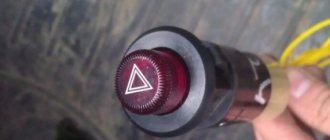
Emergency button for VAZ 2101
But sometimes you simply cannot do without this simple device on the road. In addition to its direct purpose, the hazard warning light can be used to thank the driver who let you pass, to park for a short time without formally violating traffic rules, and in general it helps to do all sorts of useful things. So, if you have finally decided to take this significant step for you and your car, then first, here is a list of necessary materials and accessories:
Installation and configuration instructions
Installing emergency lights on a VAZ 2101 is not a particularly difficult task; almost anyone can cope with it. To properly connect the emergency lights to a VAZ 2101 with your own hands, you need to prepare everything you may need to complete the task.
Set of tools and materials
So, what you need to prepare before starting the process:
- Locksmith tools, including wrenches, screwdrivers, pliers, etc.
- Insulating tape.
- Four-contact light signal relay from the “Six”.
- Six-pin button for activation.
- Five meters of installation wire (video by Alex Gordon).
Work execution algorithm
So, let's start the process:
- First you need to remove the center console. To do this, you need to unscrew the bolts that secure the trim to the steering column. You will also need to remove the side trims of the windshield pillars.
- Having done this, you can remove the instrument cluster. Be careful not to damage the device.
- Next, disconnect the wires from the light bulb that illuminates the glove compartment. Then unscrew the bolts that secure the sides of the glove compartment to the control panel, as well as the bolts that secure its lower part. After unscrewing all the screws, the glove compartment itself can be removed.
- Now you need to remove the screws that secure the bottom of the dash to the front cross member. Then the nuts of the upper fastening are unscrewed; it is best to reach them through the technological opening of the glove compartment.
- After completing these steps, you can remove the handles from the stove control panel. To do this, at the junction of the lever with the handle, use a screwdriver to bend the lower part of the upper handle, and at the lower handle, you need to bend the upper part.
- Next, you need to disconnect the connectors with wires from the control panel backlight switches, side lights, and also the stove. Then, using a wrench, you need to unscrew two more bolts that secure the fastenings of the stove control levers. After completing these steps, you will be able to dismantle the control panel.
- Now let's move on to installing and connecting the main elements. First, decide on the location of installation of the system power button. It should be installed on the center console so that the driver can reach it as quickly as possible if necessary. It’s still too early to install the button, but you need to decide on the installation location now, since this will determine how much wire you need. Now remove the old turn signal relay from the car and disconnect the three cables from it - usually they are colored black, gray-white and orange.
- Next, take a new six-wheel relay. The second contact of the relay must be connected to the wire that was removed from contact L on the turn signal relay, as well as to output 7 of the button.
- The first contact of the relay must be connected to the fourth contact on the button itself. The third contact is connected to the cable disconnected from contact P on the turn signal relay. Then you need to connect the cable from the fourth contact to ground, that is, the body of the vehicle - it is best to connect it to the relay fixing nut.
- The next step is to connect the button itself. The fourth contact of the button should be connected to the first contact of the relay used. Its second contact must be connected to the cable that was disconnected from the positive contact of the rotary relay. The seventh contact is connected to the second contact of the relay, and the first and third contacts are connected to the steering column turn signal switch; in this case, the order of connection does not matter.
- Now all you have to do is connect the eighth pin to any positive cable; alternatively, you can wedge it into the electrical circuit from the cigarette lighter. If you decide to connect the plus directly to the battery or generator unit, the circuit will need to be protected with a fuse.
- At this point, the installation procedure can be considered complete. All you have to do is securely fix the wiring to prevent chafing of the cables. Reinstall all previously removed interior trim elements, center console, glove compartment, etc.
Photo gallery "Electrical circuits"
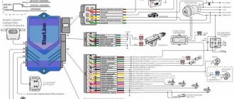
1. Relay connection diagram
2. Diagram of a penny turn switch
Price issue
The cost of an emergency warning button for a Kopeyka ranges from 100 to 400 rubles on average. As for the relay, its cost varies around 200-400 rubles.
Have you encountered problems with wiring in your car?
Survey
- Yes
- No
- I don’t know (I don’t repair my car)
Loading …
Improvement of the emergency button
Every driver uses the hazard alarm quite often, the reason for this is the established rules of behavior on the road. When a car is allowed to pass in a traffic jam, according to unwritten laws, as a sign of gratitude you need to flash your emergency lights. On some modern cars, the manufacturer installs special “thank you-sorry” buttons, which turn off automatically after a few blinks. If there is no such button, then you have to read the signals yourself and interrupt them manually. The situation can be corrected with a small improvement.
Changing the operating principle of the alarm when installing the device
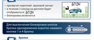
If you briefly press the emergency button, the mechanism will give a quick signal with a beeper and roll back to the last program installed by a specialist (the light is on continuously in this mode). Two presses switch to the normal alarm mode. The warning lights will flash until the driver presses the button to cancel.
After pressing and releasing the button, the device passes three beeper signals, after which it writes the next program into memory, works on it and goes into standby mode. The beeper is programmed to automatically turn off after the fourth blink of the light.
When switching from one operating mode to another, two lines of conductors are turned on (also relevant for the beeper at rest). The operating status of the device is monitored by the conductor indicator lamps on the vehicle’s instrument panel.
Operating procedure
The basis of the device is an inexpensive microcontroller (Microchip PIC 12 A 629). The brand was chosen taking into account the stock of flash memory and unused cells.
When the necessary device base is prepared, you can proceed directly to the creation of the following elements. At the first stage of work, we remove the fixation and remove the chip.
Next, you need to remove the light bulb and, carefully unhooking the clippers, remove the top cover.
After removing the moving part of the button, a metal pin is removed, which ensures its fixation. Then assembly is carried out in the reverse order.
The next step is to prepare the button itself. To do this, the wires are removed and their ends are insulated with heat shrink tubing.
The red wire must be connected to the “plus”, to a specific pin. One of the black wires will be responsible for ground, and the second will be responsible for recognition. The yellow wire should go to the light bulb.
Next you need to install the finished button in the car.
At the final stage of the work, attach the buzzer to the wiring harness using a thermal pestle or a simple clamp. The short ends must be soldered according to the diagram to the microboard, and the long ends must be attached to the car chip. It is recommended to install wires in a twisted manner.
The operating principle of the finished device that controls the alarm button is shown in the video.
In the attached ARCHIVE-1 and ARCHIVE-2 you can find the source materials and diagrams for manufacturing the device.
Turn relay VAZ 2101 connection diagram.
The turning pattern of the VAZ 2101 is based on the electromagnetic-thermal RS57. The principle of connecting the VAZ 2101 turn relay is quite simple and applied to all cars that were produced in those years. The VAZ 2101 electromagnetic-thermal turn relay, type RS57, consists of a core with a winding, a panel, two armatures, a nichrome string, a resistance and two pairs of contacts. The left armature with a pair of contacts opens and closes the circuit of signal lamps, and the right armature with its contacts ensures the operation of the indicator lamp.
Conclusion
The turn relay is a small but extremely important component of a car's warning light system. It allows the driver to be more predictable for other road users, which, of course, has the best effect on traffic safety and, to some extent, comfort. If the relay fails, the problem cannot be ignored under any circumstances. Fortunately, the relay is not an expensive component of lighting systems, so a car enthusiast can take two devices at once with almost no loss of budget - the second one will be in the trunk, garage or at home in reserve. This is exactly what we advise you to do.
Materials:
1. Electrical tape (preferably blue, as it is especially durable) 2. Four-pin turn signal relay from VAZ 2106 3. Relay connector 4. Six-pin alarm switch off button 5. Connector for the button 6. Wire for mounting and connecting the above. Tools: 1. Pliers with wire cutters 2. Flat-head screwdrivers 3. Phillips screwdrivers 4. Open-end wrench 10 5. Knife For those who want to save money at the expense of manufacturability: you can use the original relay from the VAZ 2101, but in this case it will work adequately not guaranteed as this relay is very sensitive to load changes. For this reason, the following installation method involves replacing the relay with a more modern one. Let's get started, unscrew the nut securing the turn signal relay and disconnect three multi-colored wires from it. Next, we determine where to install the hazard warning button. Here we give freedom to our imagination, but a lot also depends on what kind of panel is installed in your car. To the second contact of the relay we connect the wire removed from the contact of the old relay, marked with the letter “L”, and connect all this to the seventh contact of the alarm button. We connect the first contact of the emergency light relay to the fourth contact of the button. We connect the third contact of the relay with the wire removed from the “P” contact of the old relay. We attach the wire coming from the fourth contact of the relay to the car body. The optimal solution would be to secure the wire under the fastening nut of our relay.
Scheme of emergency lights (hazard warning lights) for VAZ 2101 cars
→ Get useful materials for VAZ 2101-2110
Thanks for subscribing!
Now tighten the relay mounting nut with moderate force so as not to break the plastic mount. Then we connect the second contact of the button to the positive wire of the old relay. We connect the first and third contacts of the button to the steering column turn signal switches in any order. The eighth contact of the button is connected to a constant “plus” (independent of the position of the key in the ignition switch). It is advisable to protect this circuit with a fuse. The most suitable would be to install a fuse rated 8A. Next, you should wrap the wires with electrical tape and secure them so that they do not dangle, and install all the previously removed casings and panels. Now we have a full-fledged alarm system and can live a new, full life. The entire procedure for installing an alarm system on a VAZ 2101 takes 2-3 hours.
Turning relay VAZ 2101 replacement with an electronic relay.
If desired, you can replace the electromagnetic-thermal relays of the VAZ 2101 with an electronic relay used on VAZs of subsequent brands. The connection is made in almost the same way. In addition to the standard wires, it is necessary to add only one wire connecting the electronic relay to the vehicle ground. In this case, you can also connect an alarm button.
admin 26/11/2013
“If you notice an error in the text, please highlight this place with the mouse and press CTRL+ENTER” “If the article was useful to you, share the link to it on social networks”