Characteristics and components of the front suspension on the VAZ 2108[/caption]The front suspension of the VAZ 2108 allows the vehicle to move smoothly when driving on an uneven road surface. What is the VAZ 2108 suspension, how is it repaired and how can its characteristics be improved? The VAZ 2108 has been known on the Russian market for more than two decades. This front-wheel drive, dynamic, quite practical car, which appeared on the sales scene in the late 80s, today also occupies one of the top levels of the rating.
And now the VAZ 2108 or, as this car is popularly called, the “eight” is in wide demand and respect among motorists. Over the years of working on the model, AvtoVAZ has released a huge number of modifications: from simple and cheap to modified, improved, more powerful and functional.
Scheme
The diagram below will allow you to determine what components the assembly is divided into and what it represents in the assembly. The table will help you figure out where each suspension element is located.
Node diagram
| Item number | What is |
| 1. | Upper shock mount |
| 2. | Spring support cup (upper) |
| 3. | Compression stroke buffer with protective cover |
| 4. | Compression Buffer Support |
| 5. | Spring |
| 6. | Spring support cup (lower) |
| 7. | Tie rod joint (ball) |
| 8. | Swivel lever |
| 9. | Strut (shock absorber) |
| 10. | Eccentric washer |
| 11. | Adjustment bolt |
| 12. | Shock absorber bracket |
| 13. | Rounded fist |
| 14. | Brake disc guard |
| 15. | Brake disk |
| 16. | Retaining rings |
| 17. | Hub cap |
| 18. | Splined shank of the wheel drive joint housing (outer) |
| 19. | Guide pin |
| 20. | Wheel bearing |
| 21. | Control arm ball joint |
| 22. | suspension arm |
| 23. | Adjusting washer |
| 24. | Shock absorber (strut) of anti-roll bar |
| 25. | Anti-roll bar |
| 26. | Barbell cushion |
| 27. | Rod fixation bracket |
| 28. | Body bracket for fixing the suspension arm |
| 29. | Lever stretch |
| 30. | Stretch Fixation Bracket |
| 31. | Suspension arm joint bushing (rubber) |
| 32. | Suspension arm joint bushing (spacer) |
| 33. | Shock absorber rod |
| 34. | Upper strut housing (outer) |
| 35. | Upper shock mount housing (inner) |
| 36. | Support bearing |
| 37. | Rubber top support component |
| 38. | Travel limiter for upper shock absorber mount |
| 39. | Protective cap for upper shock absorber mount |
| 40. | Front joint bushing |
| 41. | Front joint cushion |
| 42. | Washers |
| 43. | Stabilizer link joint |
| 44. | Rear joint extension |
| 45. | Joint housing (ball) |
| 46. | Joint bearing (ball bearing) |
| 47. | Ball pin |
| 48. | Ball pin protective cover |
Bottom view
It’s not enough just to know the name and location of the suspension elements. Be sure to understand how the entire system works and how all the components interact with each other.
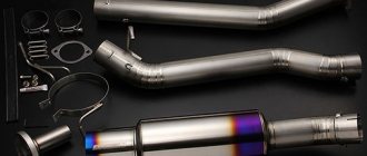
Front shock absorber device
The body 30 (Fig. 70) of the telescopic rack is made of a pipe to which the following are welded from the outside: at the bottom there is a bracket for connecting to the steering knuckle, in the middle part there is a spring support cup 27 and a swing arm 28 connected to the steering linkage.
A bottom is welded in the lower part of the housing, and a thread is cut in the upper part for nut 24. A cylinder 31 is installed in the rack body, in the lower part of which compression valve 1 is pressed in. Its body is pressed against the bottom of the rack body. The compression valve consists of a body 1, disks 2 and 3, a plate 4, a spring 5 and a cage 6. The compression valve body is cermet. In its upper part there is a slot machined with a chamfer, overlapped by disks, which are pressed against the slot through plate 4 by spring 5. The upper end of the spring rests against cage 6, which is put on the cylindrical belt of the compression valve body. To ensure the passage of liquid from the rack body to the cylinder and back, a cylindrical groove and four vertical channels are made in the lower part of the body. The same grooves are present in the upper part of the compression valve body.
Discs 2 of the compression valve are flat, made of steel tape, 0.15 mm thick, and have a hole in the center for the passage of liquid. Three cutouts are made in the central hole of disk 3 to throttle the liquid at low speed of movement of the rod. The plate 4 has a cylindrical protrusion in the lower central part, which covers the central hole of the disks 2 and 3, but does not cover the throttling cutouts. When assembled, a gap is formed between plate 4 and disk 3 for the passage of liquid. For the same purpose, eight holes are made along the periphery of the plate. The race has a flange and a cylindrical seating belt on which the cylinder is mounted, which ensures the necessary tightness between the compression valve and cylinder 31. The stamped surface of the race has six side holes and one central hole for the passage of liquid.
The cylinder contains a rod 26 with a piston 12 assembled with valves. The cermet piston has twelve vertical channels located along circles of two diameters. Four channels located along a larger radius are closed by a bypass valve plate 13, pressed against the channels by a flat spring 14. The remaining channels are covered from below by a package of two (the original version was three) recoil valve disks. The upper disk 11 is a throttle disk; it has three cutouts along the outer edge. The following discs are 10 flat. The package is pressed to the piston by a spring 8 through a support plate 9. The piston assembly with valves is attached to the rod with a nut 7, which is tightened with a torque of 1.2. 1.6 kgf m and is fixed by opening the rod in two places. To protect the recoil valve discs from damage and stabilize the valve operation, a washer is installed between the discs and the nut.
The piston is sealed in the cylinder with a ring made of filled fluoroplastic, due to which the wear resistance of the pair: cylinder - piston sharply increases. A restrictive sleeve 29 is pressed onto the rod and then welded, which, resting against the plunger 15 of the hydraulic recoil buffer, limits the recoil stroke.
The hydraulic recoil buffer consists of a plunger 15 and a spring 16, under the action of which the plunger moves down until it stops against the protrusion of the cylinder. There is a gap between the rod and the plunger, through which the cavities above and below the plunger communicate. There is a calibrated gap between the top of the plunger and the cylinder to throttle the liquid when the gap between the rod and the plunger is closed. There is a significant gap between the rest of the plunger and the cylinder due to the expansion of part of the cylinder.
The rod guide is a split sleeve 17 with a fluoroplastic insert, which is pressed into the guide cage 18. A drain tube 32 is installed in the cage channel, connecting the upper cavity of the cage with the annular groove of the telescopic rack body. This tube drains the liquid that has passed through the gap between the rod and the bushing so that there is no foaming of the liquid due to contact with air. The holder assembly with the guide bushing is pressed onto the cylinder using a cylindrical belt.
Device Features
- The suspension consists of a guide device, elastic, damping components. The guide element serves to regulate the movement of the wheels and transfer force and moment to the car body.
- The steering device includes a telescopic strut and a lower suspension arm, which are connected by a steering knuckle. Another important element of the guide device is the stabilizer bar.
- The lower arm is made of steel and mounted to the bracket. To ensure stabilization of the lever, a brace and a stabilizer bar are fixed to it. The extension is connected by means of hinges located in the hole of the lever. The opposite end of the stretcher is combined with the bracket. On the stretcher there are flats with a key and a hexagon. They serve to ensure stabilization of its position when turning the nuts.
Levers
- The rod is mounted on the suspension arm of a short strut with a pair of heads. The stand has two heads, and a rubber-metal hinge with a stand mounting bolt is inserted into one of them. The second head contains a rubber bushing where the end of the stabilizer bar passes.
- The bracket has oval holes that make it easier to install the bar on the VAZ 2109. The outer end of the suspension arm is mounted with a steering knuckle.
- The ball joint includes a one-piece housing with a bearing. The latter is made of Teflon fabric. To ensure sealing of the hinge, its cover is treated with a special lubricant - ShRB4. If this seal is not broken as the VAZ 2109 is used, then the lubricant can easily last the full life of your car.
- Adjustment of the front wheels when turning the top bolt is ensured by the presence of a special fastening of the steering knuckle to the bracket.
- The design of the steering knuckle includes a ball bearing with a hub fixed to the shank with special splines. The cap protects the hub. It is covered with dirt-reflective rings.
- The protective casing of the brake disc is fixed to the steering knuckle, which, in turn, is connected to the hub.
- The telescopic strut is connected to the body and the steering knuckle. The upper support secures the rack with the car body and is mounted on the rod. It consists of an outer and inner body.
Telescopic stand
Knowing the design of the front suspension of your own VAZ 2109 and understanding the diagram, it will be much easier for you to carry out repairs, look for weak points, and identify areas where malfunctions or breakdowns have occurred.
Suspension repair is a rather labor-intensive and complex issue, therefore, in the absence of experience and at least basic knowledge in the field of this component of the car, it is strongly not recommended to do the work yourself.
Didn't find the information you are looking for? on our forum.
- Front suspension VAZ 2109 – diagram, design, repair
If you find an error, please select a piece of text and press Ctrl+Enter.
We recommend reading:
Spark plugs for VAZ 2106 Installation of ignition on VAZ 2107 carburetor, marks, gap in breaker contacts, checking ignition Order of armored wires on VAZ 2109 Vacuum electrovalve VAZ Installation of contactless ignition on VAZ 2121 Window lifters do not work on VAZ 2115 reasons Which is better copper or aluminum heater radiator on VAZ 21 14The dimensions of the VAZ 2114 are missing
Similar articles
What kind of oil to pour into the VAZ 2115 engine? Choosing oil for the VAZ 2110 VAZ color chart, codes, names, descriptions VAZ error codes - table with a list of all errors Material from the Encyclopedia of the magazine “Behind the Wheel” Go to: navigation, search
Back
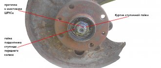
If you find an error or want to supplement the article, select that part of the article text that needs editing and press Ctrl+Enter. Next, follow the simple instructions. New topicReply Features of the design of the front suspension Repair and operation manual – Chassis – Features of the design of the front suspension The front suspension of the VAZ 2108, VAZ 2109, VAZ 21099 cars is independent, telescopic, with hydraulic shock absorber struts, coil springs, lower wishbones with braces and a stabilizer bar . The main element of the front suspension of the VAZ 2108, VAZ 2109, VAZ 21099 is the telescopic hydraulic shock absorber strut 1 (Fig. 6.1), the lower part of the shock absorber strut is connected to the steering knuckle 5 with two bolts. The upper bolt 3, passing through the oval hole of the front shock absorber strut bracket, has an eccentric collar and a washer. Turning the top bolt changes the camber of the front wheel. The following are installed on the telescopic strut: a coil spring 17, a polyurethane foam buffer 19 for the compression stroke, an upper support 22 of the front strut assembled with a bearing 21. The upper support of the front strut is attached with three self-locking nuts to the mudguard strut of the car body of the VAZ 2108, VAZ 2109, VAZ 21099. Due to its elasticity, the support ensures that the front strut swings during suspension movements and dampens high-frequency vibrations. A bearing mounted in the upper support allows the front strut to rotate along with the steered wheels. Parts of a telescopic hydraulic shock absorber, shown in Fig. 1, are mounted in the strut housing. 6.2. A hydraulic recoil stroke buffer is installed in the upper part of the cylinder, consisting of a plunger 15 and a spring 16. It limits the movement of the rod during the recoil stroke. The lower part of the steering knuckle 5 (see Fig. 6.1) is connected by a ball joint 10 to the lower suspension arm 9. Braking and traction forces are perceived by longitudinal braces, which are connected through rubber-metal hinges to the lower arms and front cross member supports of the front suspension. At the junction of the brace with the lever and the front support, adjusting washers are installed, which change the angle of the longitudinal inclination of the steering axis. A closed-type double-row angular contact bearing is mounted in the steering knuckle (Fig. 6.3); wheel hub 4 is mounted with interference on the inner rings of the angular contact bearing. The thrust bearing is tightened with nut 6 on the shank of the outer wheel drive joint housing and is not adjustable. All front and rear wheel hub nuts are the same and have right-hand threads. The anti-roll bar on cars VAZ 2108, VAZ 2109, VAZ 21099 is a bar, the knees of which are connected to the lower suspension arms through struts with rubber and rubber-metal hinges. The middle (torsion) part of the rod is attached to the body with brackets through rubber pads. USEFUL TIPS When swinging the suspended front wheel, it is difficult to discern play in the hub bearings and ball joints. Ask an assistant to press the brake pedal, and if you feel any play, the ball joints are faulty and the ball joints should be replaced. Install wheel bearing caps with any adhesive and you will avoid many problems in the future. Rice. 6.1. Front suspension of VAZ 2108, VAZ 2109, VAZ 21099 assembled:
A control size;
1 – telescopic stand; 2 – nut; 3 – eccentric bolt; 4 – nut; 5 – steering knuckle; 6 – front wheel drive shaft; 7 – protective cover of the hinge; 8 – external shaft joint; 9 – lower lever; 10 – ball joint; 11 – decorative disk (cap) of the wheel; 12 – hub; 13 – brake disc; 14 – protective casing; 15 – rotary lever; 16 – lower support cup; 17 – suspension spring; 18 – protective cover of the telescopic stand; 19 – compression stroke buffer; 20 – upper support cup; 21 – upper support bearing; 22 – upper support of the rack. Rice.
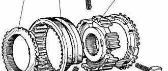
6.2. Telescopic strut of the front suspension of a VAZ 2108, VAZ 2109, VAZ 21099: 1 – compression valve body;
2 – compression valve discs; 3 – throttle disk of the compression valve; 4 – compression valve plate; 5 – compression valve spring; 6 – compression valve cage; 7 – recoil valve nut; 8 – recoil valve spring; 9 - recoil valve plate; 10 - recoil valve disc; 11 - throttle disk of the recoil valve; 12 – piston; 13 – bypass valve plate; 14 – bypass valve spring; 15 – plunger; 16 – plunger spring; 17 – rod guide bushing with a fluoroplastic layer; 18 - guide bushing; 19 – sealing ring of the rack housing; 20 – rod seal; 21 – oil seal cage; 22 – gasket of the rod protective ring; 23 – rod protective ring; 24 – nut of the strut body; 25 – compression buffer support; 26 – rod; 27 – spring cup; 28 – rotary lever; 29 – rod limit sleeve; 30 – rack body; 31 – cylinder; 32 – drain tube. Rice.
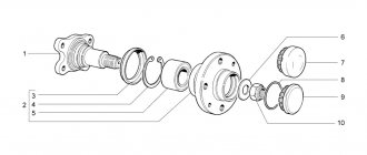
6.3. Steering knuckle and parts of the front wheel hub of VAZ 2108, VAZ 2109, VAZ 21099: 1 – steering knuckle; 2 – outer mud ring; 3 – hub bearing; 4 – wheel hub; 5 – thrust washer; 6 – nut; 7 – retaining rings; 8 – internal dirt-reflecting ring. Quote
Characteristics and components of the front suspension on the VAZ 2108[/caption]The front suspension of the VAZ 2108 allows the vehicle to move smoothly when driving on an uneven road surface. What is the VAZ 2108 suspension, how is it repaired and how can its characteristics be improved? The VAZ 2108 has been known on the Russian market for more than two decades. This front-wheel drive, dynamic, quite practical car, which appeared on the sales scene in the late 80s, today also occupies one of the top levels of the rating.
And now the VAZ 2108 or, as this car is popularly called, the “eight” is in wide demand and respect among motorists. Over the years of working on the model, AvtoVAZ has released a huge number of modifications: from simple and cheap to modified, improved, more powerful and functional.
Return to contents
Chassis of VAZ 2108 Lada Samara
- Repair manuals
- Repair manual for VAZ 2108 (Lada Samara) 1984+.
- Chassis
6.0 6. Chassis Front suspension: 1 - telescopic strut 2 - brace bracket 3 - brace 4 - front suspension arm 5 - ball joint of the lever 6 - steering knuckle 7 - anti-roll bar 8 - anti-roll bar Note Special... 6.1
. Telescopic front suspension strut. Disassembly (Category). See the list of materials inside...
6.2. Rear suspension (Category). See the list of materials inside...
↓ Comments ↓
1. Description of the car
1.0 1. Description of the vehicle 1.1 Engine compartment 1.2 General data 1.3 Technical characteristics 1.4 Passport data
2. Vehicle operation
2.0 2. Vehicle operation 2.1 Side doors 2.2 Tailgate 2.3 Opening and closing the hood 2.4 Luggage compartment 2.5 Replacing and servicing windshield wiper blades 2.6 Adjusting the front seats 2.7 Controls 2.8 Ventilation and heating of the interior 2.9 Eliminating fogging or frosting of windows 2.10 Seat belts 2.11 Refueling the vehicle 2.12 What you need to have in your car 2.13 Preparing the car for departure 2.14 Checking the wheels 2.15 Checking the level and adding coolant 2.16 Checking the level and adding oil to the lubrication system 2.17 Checking the level and adding fluid to the washer reservoir 2.18 Checking the level and adding oil to the gearbox 2.19 Checking the level and topping up brake fluid 2.20. Starting the engine 2.21 Disconnecting and connecting the battery 2.22 Removing and installing the battery 2.23 Replacing a wheel 2.24 Checking and cleaning the radiator 2.25 Raising the car 2.26 Towing 2.27 Replacing fuses 2.28 Operation during the warranty period 2.29 Running in
3. Vehicle maintenance
3.0 3. Vehicle maintenance 3.1 Checking the tightness of the cooling system 3.2 Checking the tightness of the fuel system 3.3 Replacing the coolant 3.4 Replacing the oil filter and engine oil 3.5 Checking and adjusting the parking brake 3.6 Replacing the air filter filter element 3.7 Checking and adjusting the generator drive belt 3.8 Replacing the belt generator drive 3.9 Cleaning and flushing parts of the crankcase ventilation system 3.11 Checking and replacing spark plugs 3.12 Replacing the fine filter 3.13 Checking the air filter thermostat 3.14 Changing the oil in the gearbox 3.15 Checking the front wheel drive and gear shift rod joint 3.16 Checking the condition of the front and rear suspension elements, their rubber-metal hinges, bushings and cushions 3.17 Checking the steering wheel play 3.18 Checking the condition of the steering rods, their protective caps, protective covers for the steering mechanism 3.19 Replacing the brake fluid 3.20 Checking and replacing the front wheel brake pads 3.21 Checking and replacing the rear wheel brake pads 3.22 Bleeding the brake system 3.23 Checking the efficiency of the brake system 3.24 Checking the tightness of the brake system 3.25 Checking the operation of the vacuum booster 3.26 Checking the pressure regulator 3.27 Checking and adjusting the free play of the brake pedal 3.28 Checking the exhaust system 3.29 Servicing the battery 3.30 Checking the operation of electrical components 3.31 Adjusting the headlights 3.32. Replacing lamps
4.Car care
4.0 4. Car care 4.1 Care and restoration of body paint 4.2 Body lubrication 4.3 Cleaning drainage holes 4.4. Car storage 4.5 Preparing for winter use 4.6 Tips for starting the engine in severe frost 4.7 What is useful to buy for winter 4.8 Tips for winter use of the car
5. Problems along the way
5.0 5. Malfunctions along the way 5.1. Malfunctions of the injection system 5.2. Checking electrical equipment 5.3 Extraneous knocking noises appeared 5.4 Vibration and shock on the steering wheel 5.5. Brake problems 5.6 Wheel puncture
6. Chassis
6.0 6. Chassis 6.1. Telescopic front suspension strut. Disassembly 6.2. Rear suspension
7. Steering
7.0 7. Steering 7.1 Steering column 7.2 Steering mechanism 7.3 Replacing steering rods
8. Brake system
8.0 8. Brake system 8.1 Rear wheel brake 8.2 Wheel cylinder 8.3 Brake drive
9. Electrical equipment
9.0 Electrical equipment 9.1. Generator 9.2. Starter 9.3. Lighting and light signaling 9.4. Heater 9.5. Windshield wipers 9.6 GENERAL INFORMATION 9.7. Ignition system 9.8 Instrument panel (high) 9.9 Instrument panel (low)
10. Body
10.0 10. Body 10.1 Replacing the rear buffer 10.2 Replacing the radiator lining 10.3 Replacing the front fender 10.4 Removing and installing the hood 10.5 Adjusting the hood 10.6 Adjusting the hood latch 10.7 Side door 10.8 Tailgate 10.9 Front seat 10.10 Rear seat 10.1 1 Seat belts
11. Engine and its systems
11.0 11. Engine and its systems 11.1 Adjusting the clearances in the valve drive 11.2. Power supply system 11.3. Removing the oil pump 11.4. Radiator and fan with casing 11.5. Exhaust system 11.6 Complete disassembly of the engine 11.7 Cylinder block. Inspection, troubleshooting and repair 11.8 Piston with connecting rod. Disassembly, troubleshooting and assembly 11.9. Cylinder head 11.10 Engine assembly 11.11 Replacing engine oil and oil filter 11.12 Replacing and adjusting the tension of the generator drive belt 11.13 Replacing and adjusting the tension of the camshaft drive belt 11.14. Carburetor adjustment
12. Transmission
12.0 12. Transmission 12.1 Removing the gearbox 12.2 Installing the gearbox 12.3 Adjusting the clutch drive 12.4 Disassembling the gearbox 12.5 Inspection and troubleshooting of gearbox parts 12.6. Secondary shaft of the gearbox 12.7 Primary shaft of the gearbox 12.8. Differential 12.9 Synchronizer 12.10 Gear shift mechanism 12.11 Gearbox assembly 12.12 Gear shift lever 12.13 Changing the oil in the gearbox 12.14 Replacing the clutch 12.15. Clutch drive 12.16. Front wheel drive
13. Basic data for adjustments and control
13.0 1. Basic data for adjustments and control 13.1 2. Fuels and lubricants and operating fluids 13.2 3. Tightening torques of threaded connections 13.3 4. Service book 13.4 5. Electrical diagram of the VAZ-2108
Technical characteristics of VAZ 2108
Work on the VAZ 2108 began in the early eighties. The car turned out to be original, smart, fast. The slightly elongated hatchback body evoked extremely positive emotions. Here elegance was perfectly combined with simplicity, dynamism with practicality. In addition, like all cars of the Russian concern, the VAZ 2108 was offered at an affordable price. The repairability of the model is also considered one of its positive properties.
In 1993, manufacturers decided to improve the technical part and updated the line of engines. If previously only a 1.3-liter gasoline engine was offered, now, in addition to it, there were 1.1 and 1.5-liter gasoline units equipped with different fuel injection systems. The engines operated with front-wheel drive, which was new on the Russian market at that time, and a standard manual transmission.
- Rear suspension of VAZ 2114: design, advantages and disadvantages
The car's suspension is mediocre; it doesn't filter out road irregularities very well, and if you drive on an imperfect track at a decent speed, the sensations won't be the most positive. In addition, the front suspension of the VAZ, as well as the rear, often fails. Fortunately, it is quite possible to carry out repairs yourself.
Return to contents
Tuning the G8 suspension
How will the front and rear suspensions of the VAZ 2108 be improved? Our goal is to make the G8 suspension more efficient, more reliable, and turn the car itself into an ultra-powerful system. What can be done to achieve it? The most effective thing is to automate the chassis of the car. To do this, you can either purchase a ready-made kit right away and simply install it, or, if you have at least some experience as a car mechanic, make this kit yourself.
First, we purchase sports struts and check a system such as wheel alignment. It is this system that affects the wear of the suspension; if there is even the slightest violation in it, then the suspension itself wears out, and its performance decreases. In general, we adjust the angles of car wheels. After proper adjustment, the car acquires better handling and dynamics, and even takes sharp turns easily.
Now, having checked the wheel alignment, we proceed to the most important part of the work - replacing the struts. It is important to remember one simple rule here: you only need to replace the racks in pairs. If you save on this matter and change only one, then the balance and height will be disrupted, and a serious failure will appear, which will negatively affect the chassis.
Characteristics and components of the front suspension on the VAZ 2108
In order to replace the racks, you will have to arm yourself with wrenches and spring ties. Now the work process itself. We unscrew the two bolts that are located at the bottom of the lever and one nut. It is located above, where the stem is. After this, you can remove the shock absorber. The next step is to remove the inner tube. Using zip ties, wrap around the spring and remove.
Repairing the front suspension is a more labor-intensive process, as there are springs that complicate the work. To deal with the springs, we install ties on them, compress and turn them with a wrench. Now we move the spring onto the pre-prepared stand and install it in the reverse order.
Finally, it is worth explaining why shock absorbers break. Firstly, this happens due to a reckless driving style on a difficult road. If you often drive through holes and ruts with the speed set at the maximum level, then do not expect the shock absorbers to calmly accept such loads. When driving like this, they are the first to fail.
The second cause of breakdowns is intensive engine operation without warming up in cold weather. And finally, the last thing is spacers, which, on the one hand, make the suspension more efficient, but on the other hand, they quickly damage its components.
- Life hack: front suspension of a Priora car - how to disassemble it, diagram
If you find faults with the front suspension, you should not delay repairs. Remember: not only your safety, but the safety of your passengers depends on the chassis of your car.
Return to contents
Installing an air suspension on a VAZ 2108 as a radical compromise
If you are one of those who are still torn, choosing between increased handling and additional comfort, there is a wonderful solution - the air suspension on the VAZ 2108, which is an additional air spacer for rigid car springs. The racks remain the same. This kind of suspension is a full-fledged pneumatic installation with a corresponding set of components: a compressor, an electronic control unit and, of course, a receiver. The price of the issue, however, may seem quite wild for most motorists, since it confidently exceeds a thousand dollars in components alone. The advantage of this approach is that the car, lowered by trimming the coils of springs, can always be raised when driving on bad roads. Usually, only the rear suspension is equipped with pneumatics in order to compensate for the car’s sagging when transporting large loads, but the idea of installing it under the front springs is not unreasonable, when it is necessary to increase the ground clearance of the vehicle and, accordingly, the overall cross-country ability.
Features of the front suspension device
It is independent, telescopic, MacPherson type, with shock-absorbing struts consisting of hydraulic shock absorbers and springs. The suspension is complemented by an anti-roll bar. Unlike the rear suspension, the front suspension is much more complex. This is explained by the fact that the car has front-wheel drive, but there are very few parts and components. In addition to shock absorber struts and a stabilizer, these are stretch marks and a steering knuckle, as well as levers for attaching to the body and transmission.
The chassis of the VAZ 2108 is identical to many front-wheel drive budget cars. The main element of the front suspension is a strut with a hydraulic shock absorber and a twisted metal spring. At the top, a support bearing is installed in the body shell, which smooths out vibrations and prevents the rack from rolling. It also ensures that the stand rotates synchronously with the front wheels during various maneuvers.
The steering knuckle is complemented by a ball joint, which provides communication with the lower suspension arms. Stretching with silent blocks serves to compensate for forces. A wheel hub is installed in the steering knuckle on a double-row bearing, and a single bolt is used to secure the hub. The stabilizer is also connected to the levers using silent blocks.
Return to contents
Suspension selection
The main rule when selecting any spare parts is quality and reliability. The suspension performs important functions, and not only comfort, but also vehicle handling depends on the choice of spare parts. Properly selected, it should serve its purpose equally well in any conditions and on any road surface. Ultimately, suspension affects safety.
The VAZ 2108 car has a relatively light weight, and therefore (if you are not planning races on the track) you should not choose too stiff a suspension. The optimal solution as an alternative to the standard one can be called the VAZ-KW and some similar settings. Their main advantage is the ability to smooth out vibrations of the body equally well at any speed. In addition, the components and parts are distinguished by their reliability and high performance characteristics.
When choosing a suspension, you should consider the following nuances.
- For a smoother ride, you should take a soft one. The parts must be identical to the factory ones so as not to interfere with other components of the car. When making turns, the car should not roll, and when going over bumps, smooth them out and return the car to its starting position.
- Wheel and body vibrations, as well as vibrations, should be greatly reduced.
- The force from the drive wheels on the frame must be correct and uniform.
- The overall weight of the suspension is not too large so that excess load is not transferred to the body.
- The parts must have a good margin of safety, so they will last much longer.
In addition, the suspension must be selected taking into account the use of the vehicle. For lovers of measured movement and quiet driving, you need one type. For adherents of an aggressive driving style, another one will be suitable.
Return to contents
Difficulties in replacing suspension
In general, this is not considered a complex process. Car enthusiasts will not have to deal with making homemade components. Parts for tuning are available in stores in huge quantities.
When choosing a pendant, you should also take into account such an important factor as cost. Installing an independent node will cost at least twice as much as a standard one. However, by paying more, you can get improved handling and stability of the car. One of the universal solutions could be a semi-independent chassis, which in its characteristics is similar to an independent one, but is in many ways superior to the standard one.
For aggressive driving and high speed, you should not install too soft a suspension. Otherwise, on sharp turns the car will roll heavily and lose control, which can ultimately lead to a serious accident. If serious tuning is planned, almost all standard parts will have to be replaced.
You should start by replacing the stabilizers: the standard ones will not cope with the load, so it is better to purchase a stabilizer from a VAZ 2110. It should be taken into account that you will have to change the shock absorber struts along with them. It is also better to change the shock absorbers; for efficient operation it is recommended to use gas ones. For greater stability, a spacer under the hood between the front pillars will not hurt.
Even such a minimal set of modernization will have a positive effect: rigidity will increase, and handling will noticeably improve. The car will hold the road better when cornering, and roll will be reduced even at high speed. For further tuning, you will need to install stiffer springs, this will also have a positive effect on handling, and the ground clearance will increase slightly. To reduce ground clearance, you will have to additionally buy shortened shock absorbers. Cutting springs into several turns to lower them is highly not recommended, as the consequences can be unpredictable. Even with factory shortened springs, you need to understand that the suspension will perform somewhat worse.
Return to contents
Product description
SS20 bumper for VAZ (compression stroke buffer)
A special feature of SS20 polyurethane foam fenders is a unique offer for their modifications. Shock absorber bumpers are manufactured in four options: Standard, Comfort, Highway, Sport
Applicability
- VAZ 2108-2199, 2113-2115
- VAZ 2110-2112
- VAZ 1117-1119 (Lada Kalina)
- VAZ 2170-2172 (Lada Priora)
Advantages of using SS20 polyurethane foam bumpers in VAZ cars
- protect the suspension from breakdowns;
- increase vehicle stability on sharp turns;
- operate reliably in the temperature range from -40ºС to +100ºС;
- petrol and oil resistant;
- Overall dimensions correspond to standard bumpers.
Warranty 1 year Description Purpose, design and operation of bump stops The shock absorber bump stop (compression buffer) is designed to reduce shocks in the suspension at maximum loads and act only as an elastic mechanical limiter that prevents metal impacts (true for any car, be it a VAZ or a foreign car). Buffers operate over a greater distance of the suspension travel (for example, on a VAZ 2110 at almost half the travel) and such bumpers affect the elastic characteristics of the suspension. The polyurethane foam bumper works in conjunction with the spring and helps it under high loads, preventing suspension breakdowns. The bump stop comes into operation during the compression of the suspension and is compressed together with the spring, accumulating impact energy. Working together with the spring, the bump stop provides a progressive compression characteristic of the suspension - that is, with increasing compression, it increases its rigidity. So at the end of the suspension compression stroke, the load experienced by the bump stop is even greater than the load on the spring.
The influence of the bump stop on the comfort of vehicle movement and other consumer properties
The influence of the bumper on the comfort of vehicle movement and other consumer properties. The elastic characteristics of the bumper depend on two factors - the shape of the bumper and the density of the material. Bump stops for different cars vary in both shape and height. The bumper is molded from polyurethane foam and its rigidity depends on the density of the polymer. The photo shows two different bump stops of different hardness under high magnification. It is clearly visible that the softer (on the left) bumper has a loose structure, while the harder one (on the right) has a higher density and the bubble size is smaller. The wrong choice of bump stop can either lead to suspension breakdowns at maximum loads, or, conversely, if it is too hard, turn the car into a stool (just like the wrong selection of springs). Operation and defects The rigidity of the fender changes during operation, so at low temperatures the fender becomes stiffer; in addition, the rigidity of the part is affected by the aging of the material and the ingress of operating fluids onto it. Over time, the structure of the fender material begins to deteriorate (the bridges between the bubbles burst) and the fender reduces its rigidity. As a result, more frequent and more severe impacts on breakdown in the suspension.
Expert opinion
! Expert adviceAsk a questionVK profileRuslan KonstantinovMore about the expertRuslan Konstantinov – 10 years of professional car repair experience. Graduated from Izhevsk State Technical University named after M.T. Kalashnikov with a degree in OPERATION OF TRANSPORTATION AND TECHNOLOGICAL MACHINES AND COMPLEXES. The specialization of work varies, from diagnostics and repair of engines and transmissions to consultation on the purchase of consumables. Experience in repairing electronic components. When planning suspension tuning, you need to clearly understand that you will need to upgrade not only the front, but also the rear. In addition, this is a serious financial investment. It should also be taken into account that VAZ-2108 cars have been out of production for a long time, and copies in perfect condition are very rare. You must be prepared for additional costs for replacing parts with discovered defects: for example, wheel bearings, brake discs, calipers, CV joints, etc. Often such tuning costs more than the price for the entire car on the secondary market. Although for true connoisseurs of the “chisel” this does not matter.–> VAZ Masters / Chassis / Repair
Front suspension of VAZ 2108
Rear suspension of VAZ 2108
Chassis system of the VAZ 2108 car
The front and rear suspensions make up the chassis of the VAZ 2108. The independent telescopic front suspension consists of:
- Hydraulic front shock absorber struts with a swing arm on which the steering pin is attached.
- Lower wishbones, with braces and anti-roll bars.
- On both sides there are screws with coil springs necessary to reduce the load on the racks.
- The lower ball joint connects the lower control arm with a swing arm.
- The longitudinal rods, connected to the front supports and the lower arm through metal bushings, dampen the traction and braking forces acting on the suspension while the vehicle is moving.
The rear suspension includes:
- Body vibrations are dampened by hydraulic shock absorbers, which include coil springs.
- Beam.
Repair of front suspension components
After an accident, in case of mechanical damage or replacement of silent blocks, it is necessary to remove the front suspension arm from the car. Damage to silent blocks can be determined by bulging or cracking of the rubber. Repair work is carried out in a pit or overpass, in a stationary vehicle. Work order:
- The ball joint is removed. The finger is released from the cotter pin, the nut is unscrewed and, using a puller, the finger is pressed out of the lever.
- The nut securing the anti-roll bar is unscrewed from the lever, and the rear brace mounting nut is loosened.
- The nut holding the lever on the car body bracket is unscrewed and the lever is removed from the front suspension.
- All necessary repairs to the parts are carried out, and the unit is installed in place in the reverse order of its removal.
Repair of front struts of VAZ 2108
On a VAZ 2108 car, in extreme cases, a situation arises that requires repair or replacement of the front struts. Most often, they are replaced on both sides with new ones. The front springs are replaced after disassembling the struts. Repair work is carried out using a set of standard tools and special spring ties. Work order:
- The stand is removed from the car.
- Using a wire brush removes dirt.
- Ties are installed on the springs, with the help of which the upper cup and the nut located on the shock absorber rod are released from tension.
- After tightening the spring, the shock absorber rod nut is unscrewed, and the upper support and spring are removed, along with the ties.
- The travel stop buffer and rubber casing are removed from the rod. If the removed parts are damaged, they are replaced with new ones.
- The stand is installed in a vertical position, the rod is pumped up and down several times. There should be no jamming, knocking, or failure. Otherwise, the shock absorber is replaced with a new one.
Tip: Before installing new parts, the shock absorber body must be washed with clean gasoline.
Advice: After completing work on replacing the struts, it is necessary to check the wheel alignment, which, if necessary, is adjusted by specialists from a specialized workshop.
Repair of jet traction – anti-roll bar
Periodically, when operating a VAZ 2108 car, it is necessary to replace worn parts of the anti-roll bar. This is done to restore the necessary performance characteristics of the suspension after diagnosing the front suspension. The stabilizer includes:
- barbell;
- racks;
- rubber cushions.
After installation and securing the car from moving on the inspection hole, the order of work is as follows:
- The stabilizer and adjacent elements are cleaned of dirt.
- The nuts securing the side stabilizer struts are unscrewed.
- The brackets for the rubber supports are released from their fastenings and removed from each side.
- The stabilizer bar is removed from the car.
- When replacing only the front struts with the bushings located on them, after removing their fixation, use a rubber hammer to knock the elements off the rod.
Replacing front strut braces
Replacement of extensions is carried out when it is necessary to update the chassis of the front suspension or after an accident if the extension has failed. First, you need to treat all threaded connections with a special liquid WD-40, which corrodes rust deposits, or with pure gasoline. So:
- The tightening of the nuts securing the front and rear fastening of the brace is loosened. Then the bolts securing the brace, located on the bracket and fixing it to the car body, are unscrewed.
Replacing front strut extensions on a VAZ 2108
- The stretcher is freely removable.
Tip: Before removing the brace, you need to calculate the number of shims at the rear and front ends.
The extension, rubber silent block and bracket are visually examined and all damage is identified. After eliminating defects or replacing heavily worn elements, assembly is performed in the reverse order of disassembly.
Advice: If the car is pulled to the side after repairs, you need to contact a workshop where the front suspension will be diagnosed.
Replacing the ball joint
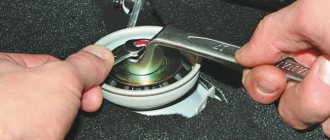
The appearance of a metallic knock while driving a VAZ 2108 car may indicate a failure of the ball joint. You can determine whether the ball joint is out of order after lifting and fixing the wheel in a stationary state using the brake pedal, then when the car rocks, the presence of play in the ball joint will be clearly audible. The support is changed if the seal of the rubber boot is broken. Procedure:
- The car is installed on the inspection hole. The nut securing the ball joint is cleaned of dirt. The nut holding the pin is unscrewed.
- After installing the puller, the pin is pressed out of the lever.
- The lever is pressed down, the bolts securing the ball joint to the steering knuckle are unscrewed.
- The support is removed from the car.
- The new unit is installed in the reverse order of removal.
Tip: Installation of a new support must be done after lubricating the rotary pin with lithol, and the rubber boot is half filled with grease. Be sure to replace the ball mounting bolts with new ones with self-locking nuts.
Assembly of the front pillar of VAZ 2108, 2109, 21099 cars
After the front pillar of the VAZ 2108, 2109, 21099 cars was removed and disassembled, it was time to replace the faulty parts and put it back together.
Necessary tools and equipment
Screeds can be of different designs; here, the simplest ones are used as an example.
— Special wrench for unscrewing the shock absorber rod nut
Preparatory work
— We clean the parts of the rack that are planned to be reinstalled from contamination
— We replace faulty rack parts with new, serviceable ones
— Clamp the front pillar housing in a vice (by the bracket so as not to crush it)
Assembly procedure for the front pillar of VAZ 2108, 2109, 21099 cars
— Install the shock absorber cartridge into the strut housing
If you use an old cartridge, check its functionality before installation. Using your hands, press and push the shock absorber rod as far as possible several times. The rod should be recessed quite easily into the shock absorber and be pulled out with great effort. The movement of the rod of a working shock absorber should be smooth, without dips or difficulties. The rod itself should not have any damage, signs of corrosion, or deformation.
When installing a new shock absorber, it is also recommended to check its serviceability using the method described above. More information about the choice of new shock absorbers for the front struts: “Shock absorbers for the front struts of VAZ 2108, 2109, 21099”. A new strut housing nut usually comes with a new shock absorber.
With the shock absorber rod fully extended, install and tighten the strut housing nut with a special wrench. Tightening torque 12-15 kgf.m (117-147 N.m).
We tighten the nut of the strut housing using a special wrench
— Install the front suspension spring
If the spring is reused, inspect it visually. A heavily corroded and/or sagging spring must be replaced.
New springs have different lengths under test load and are therefore marked with different colors of paint (on the outside of the coils). Class “A” springs are stiffer and are marked with yellow or white paint. Class “B”, less rigid, green (blue). Springs of the same class should be installed in the front and rear suspension of the car (either all “A” or all “B”). Installation is allowed in the front class “A”, in the rear class “B”. This should be taken into account when selecting new springs for your car.
Repair of rear suspension components
Replacing the rear suspension beam
Sometimes there is a need to replace the rear suspension beam of a VAZ 2108 car. This may be after an accident, an unsuccessful trip on a bad road, hitting a curb or bump, which can lead to deformations and violations of the general characteristics of the rear suspension elements of the car. So:
- To carry out work on replacing the rear suspension beam, the rear part of the car must be suspended and freed from the total weight so that the beam is in a free state.
- All attachments are removed - the fixation of the rear shock absorbers, hoses and brake pipes, and the ends of the handbrake cables are disconnected.
- The pressure regulator earring is disconnected from the bracket located on the suspension beam.
- The nuts holding the bolts attached to the brackets of the lower part of the shock absorbers are unscrewed, after which the latter are moved to the sides.
- The last stage is to unscrew the bolts fastening to the bracket of the beam itself.
- After removal from the vehicle, all elements are subject to visual inspection. If necessary, they are restored or replaced with new ones.
- Assembly of the unit is performed in the reverse order of disassembly.
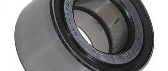
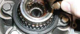
Replacing the rear wheel bearing of a VAZ 2108 car
When there is play in the wheel, which can be easily determined when driving, there is noise from behind the car, a knock. If there is a small gap, you can try to tighten the hub nut. This will slightly prolong the use of the bearing, but to completely eliminate the problem, it must be replaced. So:
- To work, in addition to the tool, you will need a hub puller, a mandrel to knock out the old bearing race, or a piece of pipe of the required diameter.
- The side of the car being repaired is raised. The wheel unscrews.
- The brake pads and drum are removed.
- Using a small piece of pipe as a lever, the hub nut is unscrewed and removed along with the thrust washer.
- The hub is removed from the axle using a special puller.
- Next, the failed bearing is replaced.
- The hub is clamped in a vice, from which the retaining ring is removed.
- The old bearing is removed using a puller or mandrel.
- The hub is washed with clean gasoline, lubricated with lithol and a new element is pressed into it.
- A new retaining ring is installed.
- The brake mechanism is assembled, the wheel is screwed into place, and the car is lowered to the ground.
- The tightening of the hub nut is adjusted, which then needs to be locked.