1 – block headlight; 2 – electric motors for headlight cleaners; 3 – fog lights; 4 – engine compartment lamp switch; 5 – sound signal; 6 – electric motor of the engine cooling system fan; 7 – fan motor activation sensor; 8 – front brake pad wear sensor; 9 – generator; 10 – solenoid valve for turning on the headlight washers; 11 — solenoid valve for turning on the rear window washer (installed on parts of manufactured cars); 12 – solenoid valve for turning on the windshield washer; 13 – windshield washer motor; 14 – oil pressure warning lamp sensor; 15 – oil level sensor; 16 – washer fluid level sensor; 17 – fuel consumption sensor; 18 – carburetor solenoid valve; 19 – carburetor limit switch; 20 – starter activation relay; 21 – spark plugs; 22 – ignition distributor sensor; 23 – vehicle speed sensor; 24 – carburetor solenoid valve control unit; 25 – diagnostic block; 26 – ignition coil; 27 – reverse light switch; 28 – coolant temperature indicator sensor; 29 – starter; 30 – top dead center sensor of the 1st cylinder; 31 – switch; 32 – battery; 33 – coolant level sensor; 34 – relay for turning on fog lights; 35 – brake fluid level sensor; 36 – mounting block; 37 – plug socket for a portable lamp; 38 – door lock control unit; 39 – engine compartment lamp; 40 – electric motor for windshield wiper; 41 – glove box lighting lamp; 42 – heater fan electric motor; 43 – additional resistor of the heater electric motor; 44 – heater fan switch; 45 – backlight lamp for heater levers; 46 – gearmotors for electric windows of the front doors; 47 – gearmotors for blocking door locks; 48 – ignition switch; 49 – right door power window switch; 50 – left door power window switch; 51 – ignition relay; 52 – steering column switch; 53 – trip computer; 54 – cigarette lighter; 55 – instrument lighting regulator; 56 – parking brake warning lamp switch; 57 – brake light switch; 58 – indicator lamp for turning on the heated rear window; 59 – rear window heating switch; 60 – fog lamp switch; 61 – control lamp for turning on fog lights; 62 – indicator lamp for turning on the rear fog light; 63 – rear fog light switch; 64 – side direction indicators; 65 – lamp switches on the door pillars; 66 – fog light circuit fuse; 67 – external lighting switch; 68 – instrument cluster; 69 – carburetor air damper warning lamp switch; 70 – alarm switch; 71 – interior lamp; 72 – connector for connecting to the individual lighting lamp; 73 – rear lights; 74 – license plate lights; 75 — electric motor for rear window wiper; 76 – rear window heating element; 77 – sensor for level indicator and fuel reserve;
A – the order of conditional numbering of plugs in the blocks of the mounting block, instrument cluster, steering column switch, ignition switch and windshield wiper; B – the order of conditional numbering of plugs in the headlight and rear window wiper blocks; B – the order of conditional numbering of plugs in the blocks of speed and fuel consumption sensors and in the ignition sensor-distributor; D – the order of conditional numbering of plugs in the blocks of gear motors for power windows and gear motors for locking door locks.
1. In the instrument panel wiring harness, the second ends of the white wires are brought together to one point, which is connected to the instrument lighting switch. The second ends of the black thin wires are also brought together to points connected to ground. 2. The diagram shows the connection of additional electrical equipment that can be installed on cars, but a car of a particular configuration may not have one or another auxiliary unit or system.
This is interesting: Renault Logan front suspension diagram and repair
Disassembling the panel
We arm ourselves with tools and start disassembling. At first:
- Disconnect the battery;
- Remove the front panel (it is secured with latches and screws);
- We remove the instrument assembly;
- Carefully disconnect all contacts and connectors on the wires;
- Remove the plastic panel from the steering column;
- Disconnect the ignition switch and dismantle it;
- We release the wiring harnesses going into the engine compartment;
- We remove them through the technological hole.
A low panel is mounted on a shelf in the garage
Advice: do not use force - the latches on the panel are pryed off with a screwdriver. You may still need the old panel, so keep it in working order. And the growing price on the secondary market for old spare parts also contributes to this.
Dimensions diagram for VAZ 2108, 2109, 21099
We present the electrical connection diagrams for turning on the “dimensions”, the engine compartment lamp and the license plate lights (exterior lighting) of VAZ 2108, 2109, 21099 cars.
One diagram is for VAZ 2108, 2109, 21099 cars with a high instrument panel, the second is for the same cars, but with a low panel. External lighting (“dimensions”) diagrams for VAZ 2108, 2109, 21099 cars
Electrical connection diagram for external lighting of VAZ 2108, 2109, 21099 cars produced after 1998 with a high instrument panel (dimensions, engine compartment lamp, license plate lights), fuse and relay mounting block 2114 electrical connection diagram for side lights, engine compartment lamp, license plate lights sign (external lighting) of VAZ 2108, 2109, 21099 cars with a low instrument panel, before 1998, with mounting block 17.3722
Notes and additions
— On VAZ 2108, 2109, 21099 cars produced before 1988, side lights could be turned on either for the right or for the left side separately. This was done using a special switch with the key in the ignition switch in the “O” - “Parking” position.
More articles on electrics of VAZ 2108, 2109, 21099 cars
— Side lights do not work on VAZ 2108, 2109, 21099 cars
— Brake lights do not work on VAZ 2108, 2109, 21099 cars
— Turn indicators do not work on VAZ 2108, 2109, 21099 cars
— The reverse light does not work on VAZ 2108, 2109, 21099 cars
— Fuses and circuits of mounting blocks they protect for VAZ 2108, 2109, 21099 vehicles
twokarburators.ru
Removal and connection process
This is the most critical area of work, because:
- All sensors and actuators are located in the engine compartment, information about the operation of which is displayed on the instrument panel;
- There is a high panel in the cabin, which is connected to the engine compartment sensors;
- Between them is a steel panel of the engine compartment, through which the wiring is routed.
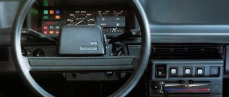
Photo of the terminal block under the VAZ 21099 panel
Reconnecting the fuse box
The most correct and reliable option is to put a new one next to the fuse box and use it as a visual aid. Better yet, record it on video.
For reference: But this is if a new wiring harness is laid nearby, and this will not be possible until the old wiring is dismantled.
- We arm ourselves with a notepad and pen;
- We record the location of the terminals and wires.
Tip: It’s good if at this moment there are instructions nearby so that you understand which electrical circuits are protected by a specific fuse.
A DIY electrical circuit will protect you from mistakes.
Replacing wiring
Having remembered the location of the wires and sketched their connection points, we proceed to replacing the wiring. For this:
- From the engine compartment we take out the wiring harness going into the cabin;
- Instead, we thread a new set;
- Disconnect the terminals from the sensors and reconnect with new wires.
Tip: The number of wires in the wiring harness is quite large. In addition, the wires are of different lengths and are collected into smaller bundles for convenience. Do not disconnect them, because they are arranged for greater convenience.
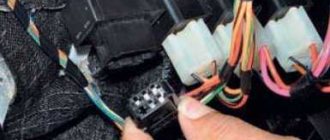
The wiring terminals are the same - there will be no problems
Connecting sensors and panel
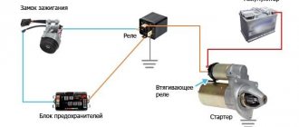
Another important step is connecting sensors and actuators. These include:
- Ignition system (from the ignition switch, which we dismantled - start relay)
- Sound signal;
- Electronic tachometer;
- Brake fluid sensor;
- Temperature sensor;
- Fuel level sensor.
Additional insulation of connections
Inside the cabin, all the wires are combined into terminal blocks, which connect the wiring to the instrument panel. Everything is extremely simple and will not cause problems.
And then you have to:
- Assemble the plastic parts of the panel into a single whole;
- Install a new ignition switch;
- Install the cover on the steering column;
- Check the functionality of the new panel.
VAZ 21099 - electrical diagram
The following are published diagrams of electrical equipment for the VAZ 21099 1990-2008. BA3-21099 completes the model range of cars of the Samara family. The stable driving performance of traditional two-volume vehicles of this family is harmoniously complemented by a variation with a three-volume body with an autonomous luggage compartment. Among the prestigious trinity of VAZ front-wheel drive sedans (2115, 2110, 21099), the “ninety-ninth” model is the most affordable. Responding positively to tightening environmental requirements and striving to increase comfort for its potential owners, the VAZ-21099 purposefully acquires the necessary design improvements. The car has a more economical engine with distributed fuel injection, an exhaust system with a converter that meets international toxicity standards, and a new instrument panel inherited from “Samara - 2”.
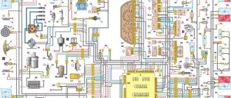
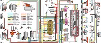
Basic electrical diagram for VAZ 21099
1 - headlight unit 31 - windshield wiper electric motor2 - headlight wiper electric motor (installed on parts of manufactured cars) 32 - cigarette lighter3 - engine compartment lamp switch 33 - heater lever illumination lamp4 - sound signal 34 - plug socket for a portable lamp5 - cooling system fan electric motor engine 35 – engine compartment lamp6 – fan motor activation sensor 36 – glove box lighting lamp7 – generator 37 – mounting block8 – solenoid valve for turning on the headlight washer (installed on parts of manufactured cars) 38 – switch for instrument lighting 10 – solenoid valve for turning on the windshield washer 39 – switch parking brake warning lamp 11 – spark plugs 40 – brake light switch 12 – ignition distributor sensor 41 – steering column switch 13 – ignition coil 42 – exterior lighting switch 14 – reverse light switch 43 – hazard warning switch 15 – coolant temperature indicator sensor 44 – rear switch fog light 16 – starter 45 – fog light circuit fuse 17 – battery 46 – rear window heating switch 18 – brake fluid level sensor 47 – side turn indicators 19 – switch 48 – courtesy lamp 20 – top dead center sensor of the 1st cylinder 49 – connector for connecting to the lamp lamp individual lighting21 – diagnostic block 50 – lamp switches on the door pillars22 – carburetor solenoid valve control unit 51 – ignition relay23 – starter switch relay 52 – ignition switch24 – carburetor limit switch 53 – instrument cluster25 – carburetor solenoid valve 54 – carburetor air damper warning lamp switch26 – oil pressure warning lamp sensor 55 – rear lights 27 – windshield washer motor 56 – fuel level and reserve indicator sensor 28 – heater fan motor 57 – rear window heating element 29 – additional resistor for the heater motor 59 – license plate lights 30 – heater fan switch A – order of conventional numbering of plugs in the ignition switch block B - order of conventional numbering of plugs in the block of the windshield wiper electric motor
a-shema.ru
Displaying information on the instrument panel
The lamps highlight the following information:
- Availability of brake fluid:
- operation of the alarm system;
- oil pressure;
- turning on high or low beam;
- parking brake;
- heated rear window;
- turns;
- fuel level;
- coolant temperature.
This is interesting: How to install a car lift
Without extensive experience and special knowledge, it is undesirable to independently repair the electrical wiring of a VAZ car.
After the “ninety-nine” entered the automobile market, many car enthusiasts did not really know how the injector responsible for the fuel injection system worked. Until 2004, the car had a carburetor. Now, while operating the machine, it is advisable to have an understanding of the operating features of the electronic system and its interaction with the power unit. The phases in which the injector supplies fuel are controlled using a controller.
Wiring diagrams VAZ 21099 VAZ 99
A - the order of conditional numbering of plugs in the ignition switch block B - the order of conditional numbering of plugs in the windshield wiper motor block
| 1 – block headlight | 31 – windshield wiper motor |
| 2 - electric motor for headlight cleaner (installed on parts of manufactured cars) | 32 – cigarette lighter |
| 3 – engine compartment lamp switch | 33 – backlight lamp for heater levers |
| 4 – sound signal | 34 – plug socket for a portable lamp |
| 5 — electric motor of the engine cooling system fan | 35 – engine compartment lamp |
| 6 – fan motor activation sensor | 36 – glove box lighting lamp |
| 7 – generator | 37 – mounting block |
| 8 - solenoid valve for turning on the headlight washers (installed on parts of manufactured cars) | 38 – instrument lighting switch |
| 10 - solenoid valve for turning on the windshield washer | 39 - parking brake warning lamp switch |
| 11 – spark plugs | 40 – brake light switch |
| 12 – ignition distributor sensor | 41 – steering column switch |
| 13 – ignition coil | 42 – external lighting switch |
| 14 – reverse light switch | 43 – hazard warning switch |
| 15 - coolant temperature indicator sensor | 44 - rear fog light switch |
| 16 – starter | 45 - fog light circuit fuse |
| 17 – battery | 46 – rear window heating switch |
| 18 – brake fluid level sensor | 47 – side direction indicators |
| 19 – switch | 48 – lampshade |
| 20 – top dead center sensor of the 1st cylinder | 49 — connector for connecting to an individual lighting lamp |
| 21 – diagnostic block | 50 – lamp switches on the door pillars |
| 22 - carburetor solenoid valve control unit | 51 – ignition relay |
| 23 – starter activation relay | 52 – ignition switch |
| 24 – carburetor limit switch | 53 – instrument cluster |
| 25 – carburetor solenoid valve | 54 - carburetor air damper warning lamp switch |
| 26 – oil pressure warning lamp sensor | 55 – rear lights |
| 27 – glass washer motor | 56 – level indicator and fuel reserve sensor |
| 28 – heater fan electric motor | 57 – rear window heating element |
| 29 - additional resistor of the heater electric motor | 59 – license plate lights |
| 30 – heater fan switch |
vaz-sputnik.ru
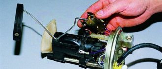
The weak link in the electrical equipment of Lada
In a VAZ car, such repairs or replacement of the device are carried out as follows. All terminals are unscrewed and wires are removed. The nut that regulates the tension of the generator belt is loosened. Then the device moves away and the belt is removed. After unscrewing the bracket and the adjusting bar, the faulty generator is removed. A new device is installed in its place. Installation of a new generator is carried out in reverse order.
To avoid problems with recharging the battery in the future, this procedure should be repeated after the next ten thousand kilometers.
Carburetor VAZ 21099
VAZ 21099 carburetor diagram: 1 - air damper, 2 - starting device, 3 - mixture quantity adjustment sensor-screw, 4 - accelerator pump, 5 - solenoid valve, 6 - carburetor cover
Design of the VAZ 21099 carburetor: 1 - first chamber, 2 - second chamber, 3 - accelerator pump nozzle, 4 - carburetor filter plug, 5 - throttle drive lever of the second chamber, 6 - throttle drive lever, 7 - throttle drive sector, 8 — air damper drive lever
It is recommended to wash the carburetor with acetone or a special carburetor cleaner and blow it with compressed air. If after this there is dirt left in the jets and channels or the jamming of the air and throttle valves has not been eliminated, complete disassembly of the VAZ 21099 carburetor is necessary.
Disassembly and repair of carburetor VAZ 21099
Unscrew the solenoid valve. Remove the fuel jet from the valve body and remove the five screws securing the carburetor cover and remove it
Using a thin screwdriver or wire, push out the float axle, then remove the axle and remove the floats
Carefully remove the carburetor cover gasket and remove the needle valve
Unscrew the four screws securing the trigger cover and remove the cover with the diaphragm
Carefully disconnect the diaphragm from the cap and remove the diaphragm spring and unscrew the fuel filter plug
Remove the plug with the filter inserted into it, if you need to remove the air damper drive lever of the VAZ 21099, carefully unscrew the axle, while removing the locking ball with the spring from under the lever, and remove the lever
Carefully pry up the accelerator pump nozzles with a screwdriver and remove them, then unscrew the four screws securing the accelerator pump cover and remove it
Remove the diaphragm and spring of the accelerator pump and unscrew the three screws securing the power mode economizer cover
Remove the economizer cap, spring and diaphragm and remove the plastic disposable plug (if installed) and turn out the mixture quality (composition) adjusting screw. You can remove the plug using a corkscrew
Unscrew the two emulsion tubes, which are structurally combined with the main air jets of the VAZ 21099 and remove the emulsion tubes
Unscrew the main fuel jets installed in the wells of the emulsion tubes, then turn over the carburetor body of the VAZ 21099 and shake out the main fuel jets
Unscrew the screw securing the wire, carefully squeezing the tabs of its tip, remove the wire from the shank of the sensor-screw for adjusting the amount of mixture and unscrew the adjusting screw for the amount of mixture. This completes the disassembly of the carburetor. Assembly and adjustment of the VAZ 21099 carburetor is carried out in the reverse disassembly sequence with the replacement of faulty parts identified after troubleshooting.
remocars.ru
Installing a new injector
If you decide to install a new injector, then you will have to partially change the wiring. To avoid mistakes when connecting a new electronic device, it is advisable to take photographs of the wires that supply power to the old injector. Next, from the passenger compartment we drag the bundle of corresponding conductors along with their connectors into the space under the hood. On one side of the terminal block the ends of the harness are connected, on the other side - the corresponding sensors.
If your car has a high dashboard, then it is necessary to partially disassemble it and remove these devices. In a car service center, the work of replacing the device costs about the same as the injector itself. So it will be much more profitable to change it yourself. By doing this, you will not only save money, but also have a good understanding of the basic principles of the electronic system.
Previously, a carburetor was installed on Ladas. For new developments in the domestic automobile industry, an injector began to be used. Due to this, another wiring harness was added connecting the controller to the fuel frame.
In the “ninety-nine” the carburetor is quite well designed and works great on almost any gasoline. It has two chambers in which gasoline is first distributed and then supplied to the piston block. In one chamber, the carburetor switches the engine from idle speed to its further throttling mode. In another chamber, the desired consistency of the combustible mixture is prepared by mixing gasoline with air. At high engine speeds, the combustible mixture is enriched using an econostat.
The carburetor of the “nine” has an offset damper. When the air flow opens it, pulling back the spring, uniform mixing of the combustible mixture occurs. When starting a cold engine, the starting device is engaged in fuel enrichment.
At idle speed, the carburetor is controlled by an economizer, which includes a control unit, a switch and a solenoid valve.
Carburetor VAZ 21099 – getting acquainted with the features of the device + Video » AvtoNovator
Serial production of the VAZ 21099 car began in the late 80s. Ninety-nine, sometimes just nine, and also, to be honest, a trough and a basin - no matter how people call this product of the domestic automobile industry. Nevertheless, despite the irony and certain problems, the model has become widespread and popular.
The secret of 99 - how is people's love justified?
The car, whose history goes back almost four decades, is still considered one of the most successful VAZ assemblies. Until 2004, all VAZ 21099 models had a carburetor engine type, and only after 2004 did manufacturers replace this device with an injector. So the carburetor 99, a symbol of the dashing 90s, is today found on the roads of post-Soviet countries no less often than modern cars.
The car has front-wheel drive, a 1.5 liter 4-cylinder engine. A VAZ car can accelerate to 160 km/h with its 70 hp. Some models have a 1.5i engine with 76 hp, although not many of these cars were produced. The carburetor of model 21099 is very economical, the average consumption of the VAZ 21099 reaches 7–7.5 l/100 km. Fuel consumption on the highway with high-quality fuel and average speed is 5.5 liters.
Carburetor design - what's inside?
The VAZ 21099 carburetor is technically very well made and is not picky about fuel quality. The device consists of 2 chambers in which fuel is distributed and further injected into the car engine. The operation of the first chamber of the carburetor ensures a smooth transition from idle to throttling mode. The main process of supplying the fuel mixture occurs in the second chamber of the device. The fuel in the chamber rises up through the tubes and mixes with air.
The main action in the operation of the second chamber is performed by the econostat - when the throttle valves are open while driving at high speed, it enriches the fuel mixture. The starting device is responsible for preparing a saturated combustible mixture when starting a cold engine. The air damper in this device is offset and opens with a flow of air, as a result of which it retracts the throttle spring and ensures uniform mixing of the mixture.
A device called an economizer is responsible for idling in the VAZ 21099 carburetor. It consists of a switch mounted on an adjusting screw, an electromagnetic valve, a control unit and a switch. The economizer shuts down during forced idle, during sudden braking of the car engine, when changing gears and while the engine is running on an incline.
This device is very useful as it prevents the release of carbon monoxide into the atmosphere. When operating at forced idle, the engine speed increases and can reach 2100 rpm. In this case, the solenoid valve is activated, which acts on the power control unit and turns it off - the fuel supply in the idle system is stopped.
Causes of failure - we make a diagnosis
Very often, owners of 99 VAZ are faced with the problem of poor engine performance, which can occur in both warm and cold seasons. One of the main reasons for this problem is malfunctions of the carburetor. The symptoms that arise during malfunctions are very easy to notice - the car does not start well, the speed on the tachometer fluctuates, unusual sounds in the form of pops can be heard from the exhaust pipe.
While driving, the VAZ 21099 may stall when changing gears. During acceleration or releasing the gas pedal, jerking and failures in operation are possible. Fuel consumption increases noticeably.
If you find problems with the operation of the VAZ 21099 carburetor, then in case of minor damage it can be repaired or replaced with a new one, if the problems are more serious. Repairing a carburetor is a delicate matter and requires experience in the work. For self-repair, you will need a standard set of tools and, preferably, a book on the maintenance and repair of this type of device.
Operation “K” - we repair the carburetor
The VAZ 21099 carburetor is located under the car's air filter cover. If you buy a new carburetor, then you should not try to disassemble or adjust it, since it is already set to the required function from the factory. Every time after you remove or replace the carburetor, it is worth washing it, as dirt can get into the internal channels of the carburetor.
To get the carburetor, you need to use a 10mm wrench to unscrew the air filter cover and slide the four latches that hold it in place. Next, you should loosen the clamps that are attached to the air filter and unscrew the four studs that hold the filter housing and carburetor. After this, you need to loosen the carburetor fuel system clamps and carefully remove them. Next, disconnect the contact wire of the solenoid valve and unscrew the carburetor cover. It must be removed in such a way as not to catch the walls of the float chamber.
Place all unscrewed screws in a separate box - searching for lost fasteners will take a lot of time, and not every store has them freely available. After disassembling the carburetor, you need to check the positions of the floats in the chamber and, if possible, adjust them. The chamber floats should be parallel to the imprint of the chamber walls; this parallelism is clearly visible on the cardboard gasket of the lid. If it is not there, then you need to dilute or reduce the floats to the desired result.
After performing this procedure, the floats should move freely in the chamber and not touch its walls. The distance between the protrusions on the floats and the cardboard spacer should be on average 1 mm; it is best to measure this distance with a caliper.
If there are significant deviations, then the fuel level in the chamber is incorrect. The fuel level should correspond to the red stripes that are in the chamber; it is best to look at them immediately after removal, so that the gasoline does not have time to evaporate. You can also navigate along the ribs in the fuel chamber; to do this, you need to bend or bend the float tongue and pump fuel into the chamber manually. This method is also very good and has proven itself in practice.
Jets and valves - cleaning the carburetor
Devices such as jets control the necessary supply of fuel from the carburetor to the engine. In some cases, the repair consists of replacing them. The working jet must have three identical round holes; with prolonged operation they wear out and can be elongated. The hole in the middle of the nozzle head must be clean; various debris from low-quality fuel or from wear of the fuel hoses can get into it. Carefully inspect the rubber seal on the nozzle - if any breaks are found, replace it.
Carry out these steps for each jet. After completing these works, screw them back into the camera - this should be done by hand, and only in some cases with a screwdriver. A very common problem in carburetor operation is caused by poor contact in the solenoid valve. This happens due to oxidation of the terminal to which the wire is attached, so it needs to be cleaned and processed. In some cases, there is a breakdown in the switch, it may fail, so you will have to replace it with a new one.
One of the main devices in the carburetor is the fuel accelerator, which distributes fuel in the chambers. In practice, there are very few cases where this is the problem, but you shouldn’t rule it out. The accelerator needs to be washed or, if possible, replaced. It is best to clean your carburetor every six months. The cleaning product is available at any auto store. This procedure will significantly extend the life of your carburetor. If you are the owner of a VAZ 21099 with an injector, then on our website there is an article about this model.
Rate this article: Share with friends!
carnovato.ru
Do-it-yourself dismantling and replacement of fuses (details)
Work order:
Good afternoon. Today we have VAZ 2108, 2109, 21099 in our service center. He came to us with the desire to deal with the electrical system. There was a power surge in the car, and after that the windshield wiper blades, turn signals, and rear fog lights stopped working. Most likely the fuses are to blame. In this article we will tell you where the VAZ 2108, 2109, 21099 fuses are located and how to change them. We also attach a detailed diagram of the fuses in the mounting block.