For greater convenience, the button for turning on the low headlights and the button for turning on the dimensions of the VAZ 2114 are made in pairs and are located on the European panel of the car. Both of them are equipped with additional built-in LEDs (two for backlighting, as well as an indication diode for side lights).
As a rule, there are no problems with the operation of these buttons, but if necessary (for example, if they break), you should know how to replace them.
Buttons for side lights and low headlights
Everything is done in the following order:
- Remove the plug under the button panel (it can be removed simply by hand, without tools).
- Push the buttons into the interior by pressing them from the inside.
- Gently pull the button, rocking it slightly, and remove it from the block.
- Install a new button into the block.
- Place the buttons back into the panel.
As you can see, the replacement can be done almost instantly, without applying any great effort or using a special tool.
Another important point that should be highlighted is the pinout of the VAZ 2114 size button. It may be needed, for example, when replacing an old type button with a button for a Europanel.
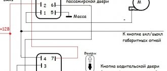
You can see it most clearly in the following diagrams: for old type buttons
for new type buttons All letters indicated in the diagram correspond to the output contacts of the buttons and have similar markings to them, and the colors of the wires are indicated by letter abbreviations.
Also, the pinout of the VAZ 2114 light switch button can help when troubleshooting problems in the operation of the buttons themselves, for example, if the backlight of one of them does not work.
In this case, it should be taken into account that the contacts:
- 6-V or 5-V - responsible for the operation of the low beam indicator;
- А-В — illumination of the low-beam headlight button;
- С-D — indicator for turning on dimensions;
- E-D — illumination of the button for turning on the dimensions.
Reworking the low beam button
As already mentioned, the button for turning on the low beam and the button for the dimensions of the VAZ 2114 are combined and located in pairs. Their main drawback, which most car enthusiasts point out, is the absence of a power-on LED on the low-beam headlight button.
- Button illumination VAZ 2114: replacement and modernization
This problem is quite serious, since very often it becomes unclear whether the headlights are working or not (especially during daylight hours). You can solve this by upgrading the button yourself.
For this you will need:
- a button that will be redesigned;
- the second button is the same - donor;
- soldering iron or (better) soldering station.
Button redesign
The button modification should be carried out according to the diagram shown here. Resoldering the LED itself from one board to another is highly not recommended, since this requires a soldering station equipped with a hair dryer, a special flux and high skill in working with them.
First, we need to remove the main button from the car panel (how to do this has already been discussed above).
After it is removed and disconnected from the wires, perform the following operations:
- remove the keys by prying them off with a flat screwdriver;
- we disassemble the body of the buttons by pressing the latches with a screwdriver (the buttons themselves at this moment must be in the “on” position);
- we see that the sidebar button has two diodes (backlight and indication), and the low headlight button has only a backlight button;
- remove a pair of legs and a pair of contacts from the donor button;
- we rearrange them into the free spaces on the working button;
- remove the board from the donor button with two diodes and insert it into the working button instead of the board with one diode;
- solder the board to the legs that were added;
- make a hole in the button cover (this can be done with a sharp knife or simply punched with a flat screwdriver).
Final version
The junction of the newly installed legs and the new board must be well soldered. Otherwise, the button may quickly fail or not work correctly.
After all these operations have been completed, all that remains is to assemble everything in the reverse order and install the upgraded button in its place (during installation, it is important that all the mini-latches on the case fall into place).
Published March 14, 2018
Domestic cars are far from perfect. Therefore, many owners are constantly improving and modernizing their equipment. One of the elements of such improvements are the front panel buttons. Overexposure of the VAZ 2114 buttons allows you to change the color of their glow and transform the interior, making it more attractive and different from the standard one.
- VAZ 2115 starter relay - where is the VAZ 2115 starter relay located
Low beam indicator
Now, in accordance with the current rules, it is necessary to drive in the daytime with low beams or fog lights on. If your VAZ 2109 does not have fog lights installed, in this article you can see how to install them. And if an indication of turning on the PTF is usually present in the car (in a Lada Samara with a high panel it is a light next to the button for turning on the PTF, with a Europanel - on the button itself), then turning on the low beam is not displayed in any way on the dashboard. The light spot from the low beam on the road when it is light outside is also not visible, so you can quickly determine whether the low beam is on during the day only by the position of the button to turn them on, which is not informative enough.
Let's set ourselves the goal of installing an indication for turning on the low beam headlights on the Lada Samara ourselves.
Let’s immediately make a reservation that in this article we will consider the option of installing an indication for turning on the low beam on the Samara europanel, where the following button is responsible for turning on the dimensions and low beam:
Let's get started. To modify the button, we will need the same donor button, since it lacks the indication LED itself, the contact antennae and the contacts themselves.
The antennae and LED are removed from the donor button and installed in the button being modified quite easily. But you will have to tinker with the contacts, since they have teeth that do not allow the contact plates to be freely removed from the button. You'll have to use a tool. You may have to cut the donor button to remove them.
The modified button looks like this:
Now we need to finalize the connection, we need to solder these wires to the contacts on the button on the contact side, either on the button itself or in the connection connector.
However, the window for the LED indicating that the low beam is on is painted over, and practically no light penetrates through it. You need to remove the paint from it using a thin screwdriver.
Here is the result.
Improvement of the illumination of the low beam key for the VAZ 2109
A slight modification of the dimensions/low beam switch button can also be done on a VAZ 2109 with a high/low panel, namely, you can make the backlight of the button itself (light bulb icon) light up when the ignition is turned on. This makes it easier to find the button by touch in the dark, especially on a low panel.
In the picture we see the low beam button of the VAZ 2109 on the reverse side. In order for the backlight of this key to light up when you turn the key, you need to place a jumper on the “+” bulb from pin 3 (power supply from the ignition switch), if you do this without a diode, then the low beam will light up even when the ignition is off. Next, so that the entire panel does not burn, we disconnect the wires that previously came to the “+” bulbs (2 wires are white with black a and b), and everything is fine, but now if you turn on the headlights and turn off the ignition, the button illumination will also disappear To this end, we also connect wires a and b through a diode to the plus of the light bulb. As a result, when you turn the key, the button lights up, and when the ignition is turned off, the button does not go out until it is turned off. For ease of installation, all operations are performed on the connector to which the button is connected.
Rate this article: Share with friends!
tuning-lada-2109.ru
Why change the backlighting of individual buttons on the VAZ 2114 dashboard
On the VAZ 2114, the illumination of the buttons for controlling the dimensions, low beam, front and rear fog lights, as well as the rear window heating is green from the factory. Over time, many owners get tired of this glow and there is a desire to replace it, make it non-standard. After making a decision about such modifications, you need to decide: do this work yourself or contact the service. Since the process of replacing button backlighting is not a complicated procedure, in most cases, car owners carry out such an upgrade with their own hands.
The standard green backlighting of the buttons gets boring over time.
Scheme of side light VAZ-2108
1 – block headlight; 2 – gear motor for headlight cleaner*; 3 – engine compartment lamp switch; 4 – sound signal; 5 – electric motor of the engine cooling system fan; 6 – fan motor activation sensor; 7 – generator; 8 – solenoid valve for turning on the headlight washers*; 9 – solenoid valve for turning on the rear window washer* (not installed on the VAZ-21099); 10 – solenoid valve for turning on the windshield washer; 11 – electric motor for glass washer; 12 – oil pressure warning lamp sensor; 13 – carburetor solenoid valve; 14 – carburetor limit switch; 15 – spark plugs; 16 – plug socket for a portable lamp; 17 – engine compartment lamp; 18 – ignition distributor sensor; 19 – carburetor solenoid valve control unit; 20 – windshield wiper gearmotor; 21 – switch; 22 – ignition coil; 23 – starter; 24 – top dead center sensor of the 1st cylinder**; 25 – diagnostic block**; 26 – starter activation relay; 27 – coolant temperature indicator sensor; 28 – reverse light switch; 29 – battery; 30 – brake fluid level sensor; 31 – mounting block; 32 – parking brake warning lamp switch; 33 – brake light switch; 34 – glove box lighting lamp; 35 – heater fan electric motor; 36 – additional resistor of the heater electric motor; 37 – heater fan switch; 38 – backlight lamp for heater levers; 39 – cigarette lighter; 40 – rear window heating switch; 41 – rear fog light switch; 42 – fog light circuit fuse; 43 – alarm switch; 44 – external lighting switch; 45 – ignition relay; 46 – ignition switch; 47 – steering column switch; 48 – instrument lighting switch; 49 – side direction indicator; 50 – lamp switch on the front door pillar; 51 – lamp switch on the rear door pillar (not installed on VAZ-2108 and VAZ-21083); 52 – lampshade; 53 – sockets for connecting individual interior lighting to the lampshade; 54 – switch for the carburetor air damper warning lamp; 55 – turn signal indicator lamp; 56 – indicator lamp for external lighting; 57 – rear fog light indicator lamp; 58 – backup warning lamp; 59 – control lamp for high beam headlights; 60 – indicator lamp for heated rear window; 61 – speedometer; 62 – instrument cluster; 63 – instrument cluster lighting lamps; 64 – coolant temperature indicator; 65 – voltmeter; 66 – fuel level indicator with reserve indicator lamp; 67 – econometrician; 68 – “STOP” indicator lamp; 69 – battery charge indicator lamp; 70 – control lamp for the carburetor air damper; 71 – hazard warning lamp; 72 – brake fluid level warning lamp; 73 – parking brake warning lamp; 74 – oil pressure warning lamp; 75 – rear light; 76 – sensor for level indicator and fuel reserve; 77 – pads for connecting to the rear window heating element; 78 – license plate lights; 79 – rear window wiper gear motor* (not installed on VAZ-21099)
Do-it-yourself overexposure of buttons on a VAZ 2114
Replacing the standard button backlighting on a VAZ 2114 will require the preparation of certain tools, materials, as well as some time. To work you will need the following list of necessary things:
- soldering iron with a thin tip;
- solder;
- tweezers;
- small knife or flat screwdriver;
- LED elements of the desired color.
Which LEDs and in what quantities should I buy?
The buttons installed on the dashboard of the model in question come in old and new styles. In the first case, small light bulbs or LEDs are used as a backlight element, and in the second, boards with sealed SMD LEDs are used.
Bulbs, LEDs and SMD elements can be used as backlighting elements in buttons.
Each button is equipped with two LED elements: one is responsible for illuminating the button itself, and the second indicates the activation of a particular function. The exception is the low beam headlight button - it does not have a power indicator LED. Therefore, if you plan to replace the LEDs on all five buttons, you will need to purchase 9 backlight elements. The type of the latter can be determined only after disassembling the button. The old model requires 12 V LEDs with a diameter of 3 mm. The new sample uses elements marked 0805. When using standard LEDs, it is recommended to additionally install a resistor with a resistance of 500 Ohms to 1 kOhm along the power circuit (directly in the button), which will prevent the element from burning out.
To prevent the LED from burning out, it is recommended to install a resistor in series
It is better to purchase LEDs with a small margin, since there is a possibility of damage to the element during installation.
How to remove buttons
To remove the buttons on the front console, do the following:
- Remove the negative terminal from the battery.
- We take out the plug of the on-board computer or the BC itself, if it is installed. To do this, just hook it with your finger and pull it towards you. To access the back of the buttons, you need to remove the on-board computer cover
- We put our hand into the hole formed and feel the back of the buttons. After removing the plug, we put our hand in and feel the connectors with wires going to the buttons
- Carefully push the buttons out. Remove the buttons from the front panel
- We remove the blocks with wires. We remove the blocks with wires from the buttons
- Having completed the necessary actions with the buttons, install them in the reverse order.
Replacing the backlight of the front panel buttons
Since replacing LEDs on old and new button versions is somewhat different, each process should be considered separately.
- The VAZ 2109 stove does not work: reasons, what fuse
Overexposure of old-style buttons
After removing the buttons from the instrument panel, perform the following sequence of actions:
- Pull the top of the button and remove the cap that is being pressed. To remove the cap from the button, just pull it
- Insert a flathead screwdriver into the button and remove the inner part. You need to remove it carefully so as not to lose the springs. Insert a small flat-head screwdriver and remove the inner part of the button
- Using a multimeter we determine the polarity of the LEDs. Using a multimeter we determine the polarity of the LEDs
- We bend the leads and dismantle the LED element. We bend the leads and take out the standard LEDs
- We bend the leads of the new LEDs and insert them into the button body, observing the polarity, after which we shorten the leads with side cutters to the required length. Bend the leads of the new LEDs with tweezers and insert them into the housing
- Reassemble the button in reverse order.
The LEDs on all instrument panel buttons change in the same way.
Overexposure of new buttons
On modern buttons we change the LEDs this way:
- We disassemble the button, as in the previous paragraph.
- After opening we find a board with installed LEDs. We determine the polarity of the elements and solder them with a soldering iron with a thin tip. We solder SMD LEDs with a soldering iron with a thin tip
- In their place, we carefully install new SMD LEDs of the desired glow color. In place of the soldered LED, we install a new one
- We reassemble the button.
To make it easier to replace LEDs, the board can be removed from the button. Depending on the button itself, the board can be inserted or soldered onto the legs.
Video: overexposure of VAZ 2114 buttons
Modernization of the buttons for turning on the headlights and low beam
The buttons for turning on the headlights and low beam headlights are made as a single element. The absence of an LED indicating that the headlights are on low beam causes inconvenience to many motorists. This is due to the fact that it is often unclear whether the headlights work or not. To solve this problem, they resort to modernizing the button. In addition to the tools listed above, you will need a similar button from which the necessary parts will be removed. The finalization process itself consists of the following steps:
- We remove the button from the panel. The button for turning on the headlights and low beam is made as a single element
- Use a minus screwdriver to pry up the keys, take them out and see that the LED is initially missing. Use a small screwdriver to pry up and take out the keys
- We disassemble the button housing by pressing on the latches with a screwdriver. At this stage the buttons should be in the pressed position.
- From the spare button we remove a couple of pins and contacts, after which we install them in the body of the element being modified. From the spare button we rearrange the contacts and pins to the modified one
- We take out the board with two LEDs from the spare button and replace it with the board with one LED element. To upgrade the button we use a board with two LEDs
- Using a soldering iron, we connect the board to the new terminals. After installing the board in the button, solder it to the terminals
- To supply power to the new contacts, we connect the contacts with copper wire according to the photo. To supply power to the new terminals, you need to make the appropriate connection
- Use a sharp knife or screwdriver to make a hole in the button cover. We modify the cover by removing a small section of plastic in the appropriate place
- We assemble the part in the reverse order and install it in place.
Video: refining the low beam switch button
how to make lighting with your own hands, including LEDs
Domestic cars are far from perfect. Therefore, many owners are constantly improving and modernizing their equipment. One of the elements of such improvements are the front panel buttons. Overexposure of the VAZ 2114 buttons allows you to change the color of their glow and transform the interior, making it more attractive and different from the standard one.
Why change the backlighting of individual buttons on the VAZ 2114 dashboard
On the VAZ 2114, the illumination of the buttons for controlling the dimensions, low beam, front and rear fog lights, as well as the rear window heating is green from the factory. Over time, many owners get tired of this glow and there is a desire to replace it, make it non-standard. After making a decision about such modifications, you need to decide: do this work yourself or contact the service. Since the process of replacing button backlighting is not a complicated procedure, in most cases, car owners carry out such an upgrade with their own hands.
The standard green backlighting of the buttons gets boring over time.
Do-it-yourself overexposure of buttons on a VAZ 2114
Replacing the standard button backlighting on a VAZ 2114 will require the preparation of certain tools, materials, as well as some time. To work you will need the following list of necessary things:
- soldering iron with a thin tip;
- solder;
- tweezers;
- small knife or flat screwdriver;
- LED elements of the desired color.
Which LEDs and in what quantities should I buy?
The buttons installed on the dashboard of the model in question come in old and new styles. In the first case, small light bulbs or LEDs are used as a backlight element, and in the second, boards with sealed SMD LEDs are used.
Bulbs, LEDs and SMD elements can be used as backlighting elements in buttons.
Each button is equipped with two LED elements: one is responsible for illuminating the button itself, and the second indicates the activation of a particular function. The exception is the low beam headlight button - it does not have a power indicator LED. Therefore, if you plan to replace the LEDs on all five buttons, you will need to purchase 9 backlight elements. The type of the latter can be determined only after disassembling the button. The old model requires 12 V LEDs with a diameter of 3 mm. The new sample uses elements marked 0805. When using standard LEDs, it is recommended to additionally install a resistor with a resistance of 500 Ohms to 1 kOhm along the power circuit (directly in the button), which will prevent the element from burning out.
To prevent the LED from burning out, it is recommended to install a resistor in series
It is better to purchase LEDs with a small margin, since there is a possibility of damage to the element during installation.
How to remove buttons
To remove the buttons on the front console, do the following:
- Remove the negative terminal from the battery.
- We take out the plug of the on-board computer or the BC itself, if it is installed. To do this, just hook it with your finger and pull it towards you.
To access the back of the buttons, you must remove the on-board computer cover.
- We put our hand into the hole formed and feel the back of the buttons.
After removing the plug, put your hand in and feel for the connectors with wires going to the buttons
- Carefully press the buttons out.
Remove the buttons from the front panel
- We remove the blocks with wires.
Remove the blocks with wires from the buttons
- Having completed the necessary actions with the buttons, install them in the reverse order.
Replacing the backlight of the front panel buttons
Since replacing LEDs on old and new button versions is somewhat different, each process should be considered separately.
Overexposure of old-style buttons
After removing the buttons from the instrument panel, perform the following sequence of actions:
- Pull the top of the button and remove the lid that is pressed.
To remove the cover from the button, just pull it
- Insert a flathead screwdriver into the button and remove the inner part. You need to remove it carefully so as not to lose the springs.
Insert a small flathead screwdriver and remove the inner part of the button
- Use a multimeter to determine the polarity of the LEDs.
Using a multimeter we determine the polarity of the LEDs - We bend the leads and dismantle the LED element.
We bend the leads and take out the standard LEDs
- We bend the leads of the new LEDs and insert them into the button body, observing the polarity, after which we shorten the leads with side cutters to the required length.
Bend the leads of the new LEDs with tweezers and insert them into the housing
- Reassemble the button in reverse order.
The LEDs on all instrument panel buttons change in the same way.
Overexposure of new buttons
On modern buttons we change the LEDs this way:
- We disassemble the button, as in the previous paragraph.
- After opening we find a board with installed LEDs. We determine the polarity of the elements and solder them with a soldering iron with a thin tip.
Use a soldering iron with a thin tip to solder SMD LEDs
- In their place, we carefully install new SMD LEDs of the desired glow color.
We install a new one in place of the soldered LED.
- We reassemble the button.
To make it easier to replace LEDs, the board can be removed from the button. Depending on the button itself, the board can be inserted or soldered onto the legs.
Video: overexposure of VAZ 2114 buttons
Modernization of the buttons for turning on the headlights and low beam
The buttons for turning on the headlights and low beam headlights are made as a single element. The absence of an LED indicating that the headlights are on low beam causes inconvenience to many motorists. This is due to the fact that it is often unclear whether the headlights work or not. To solve this problem, they resort to modernizing the button. In addition to the tools listed above, you will need a similar button from which the necessary parts will be removed. The finalization process itself consists of the following steps:
- Remove the button from the panel.
The button for turning on the headlights and low beam is made as a single element
- Using a minus screwdriver, we pry up the keys, take them out and see that the LED is initially missing.
Use a small screwdriver to pry up and remove the keys
- We disassemble the button housing by pressing on the latches with a screwdriver. At this stage the buttons should be in the pressed position.
- We remove a couple of pins and contacts from the spare button, and then install them in the body of the element being modified.
From the spare button we rearrange the contacts and pins to the one being modified
- We take out the board with two LEDs from the spare button and replace it with the board with one LED element.
To upgrade the button we use a board with two LEDs
- Using a soldering iron, we connect the board to the new terminals.
After installing the board in the button, solder it to the pins
- To supply power to the new contacts, we connect the contacts with copper wire according to the photo.
To supply power to the new terminals, you must make the appropriate connection
- Using a sharp knife or screwdriver, make a hole in the button cover.
We modify the lid by removing a small section of plastic in the appropriate place
- We assemble the part in the reverse order and install it in place.
Video: refining the low beam switch button
Experience of car enthusiasts
Having decided to relight the buttons on a VAZ 2114, it is not necessary to contact the service: you can do the modifications yourself. The procedure is not complicated and requires a minimum list of tools and basic knowledge in electrical engineering. By following the step-by-step instructions, relighting the buttons will not be difficult.
bumper.guru
Experience of car enthusiasts
Having decided to relight the buttons on a VAZ 2114, it is not necessary to contact the service: you can do the modifications yourself. The procedure is not complicated and requires a minimum list of tools and basic knowledge in electrical engineering. By following the step-by-step instructions, relighting the buttons will not be difficult.
Opening Again we take the ready-made ESP harness and cut it again mercilessly. Complications also affected the interior part. Just as in the case of lever mechanisms, they have more force than standard ones. The locations for installing headlights are strictly defined. How to connect the Duplicate button of the VAZ window regulator. Connection diagram Reasons for poor performance There are not so many reasons why the VAZ window regulator does not work well. The new lift is installed in the reverse order. To do this, you need to pry it off with a screwdriver and, moving it a little to the side, pull it out of its recess. One small disadvantage of the lever mechanism is that the speed of raising the glass is not the same. Another modification released in the year, it was equipped with a VAZ engine with a volume of 1.6 liters and a power of 82 horsepower. A modification released this year with a VAZ injection valve engine, volume 1.6 liters and power VAZ 2114.15 FORCED ACTIVATION OF THE COOLING FAN USING A BUTTON AND RELAY
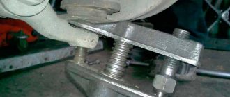
Installing a forced fan button for VAZ 2114
You should start work by disconnecting the ground terminal from the battery so that a short circuit does not occur during the connection of the electrical circuit. The procedure for installing the button is as follows:
- Prepare a block to which the button for forced activation of the VAZ 2114 fan will be connected. To do this, you need to leave 4 terminals with wires on it: two central ones for illuminating the button and two corner ones for controlling the power circuit of the electromagnetic relay.
- Connect two wires with lugs to the electric fan power wires that go to relay K1 (pins 30 and 87). To do this, you need to strip off some of the insulation on the wires approaching the relay and screw the pieces of wire that will go to the relay to them. Ideally, it is better to solder the connection, but you can get by with just a tight twist. The connection points must be carefully insulated.
- Connect the tips of the connected wires to the relay block to pins 30 and 87.
- Connect the control wire from the button block to terminal 85 of the relay, and connect terminal 86 with a wire to the vehicle ground. Install the fan switch button into a free slot on the dashboard, having first removed the plug.
- Install the relay in a convenient place, for example, under the dashboard of a car, and secure it.
- Connect ground to the battery.
- Turn on the ignition and press the fan button. The relay should click and the fan motor should turn on.
This completes the installation of the forced fan button on the VAZ 2114.
What are fog lamps for?
The first prototype of the hatchback was assembled back in the year. And in combination with high-quality manufacturing materials, it ensured reliable operation. Many PTF kits contain special decorative plugs that add attractiveness and neatness to the installed headlights and facilitate the installation process. To summarize, we can say that in the first case, the qualifications of the work are minimal, and it can be done by yourself, without having specific knowledge, while working with an electrician requires a specialist who needs to be paid. When purchasing a bumper with holes for fog lights, you will need to purchase the lights themselves and all the necessary components for connection. Self-installation of PTF is the most common installation method, since it requires minimal financial investment. Otherwise, the clip fastening can be broken, and during subsequent installation the casing will not sit tightly in place. There is a gear on the motor shaft that meshes with the teeth of the rack. It should fit between the door clip and the door frame. Driver's door switch button. Installation of the VAZ 2114 engine start button. Do-it-yourself installation.
Illuminated license plate VAZ-2107
To illuminate the license plate in VAZ-2107 cars, AC12–5-1 (C5W) type lamps are used. The license plate illumination is turned on by the external lighting switch - the first button on the left under the gear shift lever. To replace the license plate light bulb, you need to lift the trunk lid, use a Phillips screwdriver to unscrew the two screws holding the backlight light and remove the lampshade from the light housing, then replace the light bulb.
The rear lights of the VAZ-2107 car are a key element of the lighting system and perform a number of functions related to the safety of the vehicle. Proper operation and timely maintenance will extend the life of the rear lights and ensure comfortable and accident-free driving. You can give your car a more modern appearance by tuning lighting fixtures, including taillights.
Front harness diagram for VAZ 2114 injector
In this case, even if you forget to turn off the fan, it will stop working after turning off the ignition. It is this circumstance that allows this mechanism to create significant force. In addition, there is a control button on the front passenger door trim. The interior features a new instrument panel, a new steering wheel, an adjustable steering column, power windows and a new heater. A good example would be scissors. To do this, you need to pry it up with a screwdriver and, moving it a little to the side, pull it out of its recess. The mentioned wires are pulled to the fuse block from the fog light relay. Connect the tips of the connected wires to the relay block to terminals 30 and The first prototype of the hatchback was assembled back in the year. Dimensions - 4th contact in the passenger button. After releasing the door trim, there is no need to rush to remove it. Contact 5 is ground in all cases.
On the door trim, in place of the hole for the manual drive, there is a plug. This occurs due to attempts to open frozen windows. Then you need to squeeze out the clip, not the casing. The secret to the reliability of the device is the simple kinematic diagram of the transformation of the rotation of the electric motor shaft into the translational movement of the glass mounting bracket.
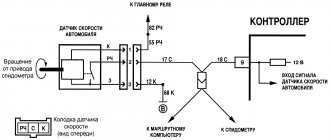
We measure the button with a caliper and transfer the dimensions onto thick cardboard. It is this circumstance that allows this mechanism to create significant force. The letter “A” in the diagram indicates the wires going to the power supply of the circuit, and the letter “B” indicates the wires going to the side lights.
F12 at 7.5 A right low beam. Sometimes vehicles are equipped with rear fog lights, the purpose of which is to improve the vehicle's visibility when driving in fog. This is especially true for the cable mechanism. The inability to ventilate the air in the cabin or reduce the temperature in the summer often reduces the composure that is so necessary for a person behind the wheel. Installation and connection of air suspension control buttons for VAZ 2114
How to turn on the high beam on a VAZ-2114: photos and videos
Car : VAZ-2114. Asks : Svetlana Ivashina. The essence of the question : How to turn on the high beam headlights?
Hello! Please tell me how to turn on the high beam on a VAZ-2114? This is my first car, so I have some small questions, and I’m somehow embarrassed to ask my friends!
High beam on VAZ-2114
On any car, high beam headlights are simply necessary, since only thanks to it you can see obstacles, potholes, sharp changes in the road surface, and animals that suddenly appear on the roads in advance, before you come into contact with them. However, you need to know that high beams can play a cruel joke when a snowstorm, heavy rain or fog appears.
The following two tabs change content below.
All my life I have been surrounded by cars! First, in the village, already in the first grade, I was rushing around on a tractor through the fields, then there was JAVA, then a penny. Now I am a third-year student at the Polytechnic Faculty of Automotive Engineering. I work part-time as a car mechanic and help repair cars for all my friends.
Remember that high beam headlights will not help you, but will rather impair visibility when driving in fog, heavy rainfall or snowstorms.
Differences in high beam switches
On different cars, that is, representatives of the domestic and foreign markets, the methods of switching the light may differ, therefore, both a beginner and an experienced driver who has switched from a foreign to a domestic car may have some questions about this.
VAZ-2114
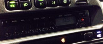
Before turning on the high beam, you must make sure that your car's headlights and low beam ; they are located on the right hand, on the “apron” of the dashboard and are marked with special symbols.
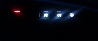
The buttons are marked with a red marker.
Next, when the main lighting is working, you can move on to additional lighting. To do this, you just need to press the steering switch on the right side “away from you” until you hear a characteristic click. So, it will be indicated that the light has turned on, and the blue control lamp will light up on the instrument panel.
High beam button
It is also highlighted with a red marker.
Brief blinking of the main beam occurs using the same lever, only by fixing it “towards you”.
On foreign-made cars, as a rule, all control of the car's light is carried out on one steering column switch (most often on the left side - approx.) by rotating it along its axis.
Advice
To ensure that driving a car with the high beam headlights on does not cause any inconvenience to the following motorists along the way, the lights must be turned off at least 150-200 meters before the intersection .
carfrance.ru
Reworking the low beam button
It, like an abrasive, increases the friction force, which creates resistance to glass movement.
Installing PTF provides better illumination of the roadside and side markings, reducing the risk of leaving the road. Some motorists are of the erroneous opinion that fog lights with high lighting efficiency can only be yellow. These grooves tend to become clogged with dirt.
This allowed additional parts to be kept to a minimum and simplified the design.
A well-known situation arises - the blinding of drivers of oncoming vehicles, which increases the risk of an accident. This is due to the geometry of the lifting mechanism. Is this really true?
We recommend: Era switch how to connect
Manual window lifters
There are 8 clips installed around the entire perimeter of the door. Replacement cost Replacing VAZ window regulators is cheaper than installing electric mechanisms to replace manual ones.
They create fewer electrical problems, but the inconvenience of using them is that while in the driver's seat, it is impossible to open the window on the passenger side without being distracted from driving. The front left window regulator fails faster due to more frequent use.
Registration
Location of relays and fuses of the old model 1 - relay for turning on the headlight cleaner K6; 2 — rear window washer time relay K1; 3 - relay breaker for direction indicators and hazard warning lights K2; 4 — windshield wiper relay K3; 5 — contact jumpers in place of the relay for monitoring the health of the lamps; 6 — relay for turning on the heated rear window K10; 7 - spare fuse; 8 — relay for turning on the main beam headlights K5; 9 — relay for turning on the low beam headlights K11; 10 - fuse; 11 — relay for switching on the electric motor of the engine cooling system fan K9; 12 - relay for turning on the sound signal K8. In the cabin, in a place convenient for the driver, a button for turning on the PTF is installed. The grille with the speaker is removed from the standard front panel. To illuminate the central locking button 4. On the driver's door there is a block of buttons that control all windows that have an electrical connection for VAZ power windows
It consists of a roller and a gearbox, which is rotated either by a handle or by an electric motor if there is an electrical circuit for the VAZ window regulator. Fill the upper part of the resulting pads with silicone. The mentioned wires are pulled to the fuse block from the fog light relay. I have not yet figured out how to overcome this problem, so I have disabled the microswitch for now and use the central lock button. Absent 8. VAZ 2110,11,12 CONNECTION OF FRONT FOG LIGHTS ACCORDING TO STANDARD
A note just in case. Continuation of the post Pinout of the MUS block
fog light button 991.3710 rear view pinout
Next, I created an ingeniously simple automatic switching on of the low beam without dimensions and without turning on the MUS. I connected the button to pins 10 and 12 on the MUS block. I stuck the button into the free socket from the cigarette lighter, removing the heater air duct lining and the diagnostics cover under the ashtray. Carefully pushed the wire there. Next, I ran the wire under the rug (or rather, under the rug under the carpet under the driver’s feet) to the fuse mounting block and soldered it to pins 10 and 12 on the MUS block. I installed a button for the fog lights so that this function can be turned off when it is not needed. Before this, contacts 10 and 12 on the MUS block were simply shorted. What yes, look at the diagram in photo 4
automatic low beam circuit
Let's shake a finger!
I searched for a long time on the Internet and electrical diagrams for the pinout of the MUS block, but I never found it...
I'm tired of constantly turning my headlights on and off while wandering around the city.
If you constantly forget to turn your headlights on or off, and the PTF or DRLs are not installed, then there is a simple way out to solve this problem.
Opening the fuse box
Next, I drew the main pinout of the MUS block under the light.
MUS block pinout
Option 1
Option 2
To automatically light up the side lamps in the rear and front lights, place a jumper on pins 9 and 10.
This option is good in winter. During the operation of this option, an interesting feature was revealed: if you turn the ICU to the parking position or low beam, the ignition key can be pulled out and the car will continue to run. By the way, I found it convenient, I start the car, take out the key, lock the car with the alarm and go home to warm up.
Personally, in winter I use option 2. And in summer, since side lights in the taillights are not needed, I use option 1.
Both of these options are good even when the ICC is broken and you really need light to drive. The MUS block can be completely pulled out and a jumper installed, but other functions of the MUS, such as adjusting the brightness of the instrument panel and the angle of the headlights, will not be available when the block is removed.
When one of the jumper options is installed and the block is connected to the MUS, all other functions of the MUS remain operational.
If you need the jumper to be disabled, you can display a separate button. I don’t recommend making jumpers directly to contacts 9+10+12! I don’t know what will happen with this option!
Connection diagram for PTF or DRL on the MUS block using a relay. A button to turn on the PTF or DRLs after turning on the headlights, because when the headlights are turned on, the PTFs or DRLs are turned off as expected.
By the way, does anyone know how to make the American version, when when you turn on the low-range PTF, the PTF goes out and then when you turn on the turn signals, the PTF turns on only from the direction from which the turn signal was turned on?
Connection diagram for PTF or DRL on the MUS block
Connection of DRL according to GOST. When the headlights are turned on, the low or high beam DRLs go out.
DRL connection diagram according to GOST on a 5-pin relay. copied from the instructions in the box
People who know about the pinout of the remaining ICC contacts, write.
- vaz-2114-lada.ru/2014/11/kak-ustanovit-protivotumannye-faryptf/
- drive2.ru/l/288230376152771088/#post
- drive2.ru/l/288230376152838641/
The modern VAZ 2114 model is in demand among domestic drivers due to its sufficient reliability, optimal cost and high maintainability. The only drawback of the model is the poor build quality. Some cars suffer from frequent electrical failures. Consequently, users often try to deal with breakdowns on their own, which without the necessary knowledge can aggravate the situation.
Tuning the rear lights of the VAZ-2107
You can add exclusivity to your “Seven” using one of the taillight tuning options available today. You can modify the rear lights using:
- use of LEDs;
- applying a tinting layer;
- installation of alternative lights.
Tinting of lamps is done with film or special varnish . Unlike tinting the headlights, for which you can get a fine, in this case the state traffic inspectorate usually has no questions about the rear lights. The main thing is that the color of all signals complies with the requirements of the traffic police: clearance and brake lights must be red, direction indicators must be orange, and the reversing light must be white.
I don’t know about anyone else - but my question was about the reflector - it clearly interferes with this device! I advise you to try this on an old taillight, using plexiglass instead of the stock one! That is, the glass of the rear light is replaced with plexiglass - but here LEDs are already asking for the headbands, and the feet, and the clearance - everything is done experimentally!
Vitala
https://forum.cxem.net/index.php?/topic/47327-%D1%82%D1%8E%D0%BD%D0%B8%D0%BD%D0%B3-%D0%B7%D0 %B0%D0%B4%D0%BD%D0%B8%D1%85-%D1%84%D0%BE%D0%BD%D0%B0%D1%80%D0%B5%D0%B9-%D0 %B2%D0%B0%D0%B72107/
Video: how the rear lights of the “Seven” are transformed after tuning
Using LEDs allows you to:
- reduce energy consumption;
- increase performance;
- increase information content;
- increase the brightness of the rear lights compared to standard lighting equipment.
On a cheap LED strip you will definitely get dots that are barely visible during the day, there’s nothing even to dispute here. If you buy expensive, good modules, it will be comparable to stock in terms of brightness, but in terms of money it will be very expensive.
Yozhyk
https://www.semerkainfo.ru/forum/viewtopic.php?f=7&t=14911
Instead of the basic rear lights of the VAZ-2107, tuning enthusiasts, as a rule, install:
- sports version with four round and two rectangular lamps;
Complete electrical diagram of the VAZ 2114 with decoding
The complete package of electrical equipment of the VAZ 2114 can be divided into two types. The fundamental differences are due to changes in equipment depending on the year of manufacture and equipment of the car. In this case, the entire drawing can be divided into several zones.
- The engine compartment is responsible for providing voltage to sensors and instruments located directly inside the engine compartment.
- Salon compartment. The part is primarily used to connect the front and rear compartments.
- Instrument panel assembly. The pinout is displayed directly on the controls and dashboard. All elements of the on-board network are combined here and connected to buttons or indicators.
- Stern joint. The small module combines chain elements located at the rear of the machine. Typically, the segment is subject to frequent damage, which is due to the constant transportation of goods in the luggage compartment. When moving over obstacles, loads can damage sensitive equipment.
You can also separate small units – these are door units, windshield wipers and others. For ease of perception, each beam is considered separately.
VAZ 2114 instrument panel pinout
The terminals of all vehicle equipment are concentrated here. Due to the fact that the unit is located under the dashboard and is subject to constant condensation or fogging, some users treat it with hot melt adhesive. Even a thin coating can reliably protect the device from water ingress.
Elements are connected to devices or controls:
- 1 – switch key for heated rear glass;
- 2/6 – fog light switches, for rear/front module;
- 3 – plastic block for activating head optics and turn signals;
- 4 – fuse block;
- 5 – wiper mode switch;
- 7 – on-board system indication;
- 8 – supply voltage to the additional harness;
- 9 – dashboard;
- 10 – “male” for powering the on-board computer;
- 11 – terminal to the ignition device;
- 12 – for door wiring;
- 13/14 – fuses;
- 16 – ignition break;
- 17 – stove motor;
- 18 – secondary resistance of the stove;
- 19 – current supply to the ignition unloading relay;
- 20 – protective relay for rear fog lights;
- 21 – starter fuse relay;
- 22 – remote socket for a portable lamp;
- 23 – power supply for the cigarette lighter;
- 24 – for illumination of the glove compartment;
- 25-27 – illuminators;
- 28 – stove switch;
- 29 – tidy lighting with rheostat;
- 30 – stop switch;
- 31/32 – horn/hazard warning switch, respectively;
- 33 – backlight of the stove panel;
- 34 – fuse;
- 35 – protective relay for seat heating elements;
- Ш1/4 – mounting block jumpers;
- X1/2 – dashboard controls;
- A – protective ground output (usually black).
Button connection diagram
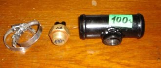
To be able to turn on the fan manually, the VAZ 2114 fan button is installed in the on-board network parallel to the thermal relay, which is triggered when the coolant temperature rises. There are two options for connecting the button: directly or using an electromagnetic relay.
In the first case, too much current will flow through the button contacts and will quickly fail. Therefore, correct connection of the fan must be done only through a relay. In this case, only a small current will pass through the button, controlling the relay electromagnet. A pair of wires is connected to the terminals of the relay contacts (those that are open when there is no power to the electromagnet): one from the output of the thermal relay, the other from the input. In this case, when voltage is applied to the relay electromagnet, the radiator fan will turn on. The “ground” of the relay can be connected to the nearest bolt, and the “plus” can be connected from the fuse block. Moreover, it is better to connect it to the output of the fuse, which is de-energized when the ignition is off. For example, to fuse F10. In this case, even if you forget to turn off the fan, it will stop working after turning off the ignition. Otherwise, there is a risk of draining the battery to zero by leaving the car in the parking lot with the fan on.
Electrical equipment of the front of the car
The following is a breakdown of the front cable bundle, excluding fog lights:
- 1 – output terminals of the starter contact group;
- 2 – battery, connection of power cables;
- 3 – standard “father” of the generator;
- 4 – blocks for connecting the power conductors of the battery and generator to the front assembly of electrical equipment;
- 5 – part of the fuse mounting block;
- 6 – standard horn;
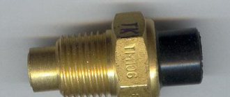
- 7 – sensor that measures the temperature of antifreeze in the power plant;
- 8 – standard sensor for measuring the washer fluid residue in the tank; when activated, the corresponding indicator on the device lights up;
- 9/10 – left and right headlights, respectively;
- 11 – external thermometer;
- 12 – standard reverse gear lamp switch;
- 13 – drive of the electric fan of the generator;
- 14 – connector to the ignition system module;
- 15 – in the VAZ 2114 scheme the injector is not used, it is used only for the carburetor;
- 16 – electronic brake fluid level sensor; in case of a critical drop, an exclamation mark lights up on the instrument panel;
- 17 – built-in oil level sensor in the crankcase compartment of the power plant; when activated, the red light on the instrument panel lights up;
- 18 – similar for the engine cooling system;
- Ш5-8 – mounting block connectors;
- A1/2, B1/2 – grounding terminals.
Designations of light bulbs, indicators, icons and buttons on the instrument panel of VAZ 2114, 2115
First, let's look at the descriptions and meaning of the panel icons and buttons, regardless of whether the car is equipped with an injector or a carburetor.
Instrument panel diagram VAZ 2114, 2115
1 — A control sensor that measures the temperature of the coolant in the engine cooling system. During normal operation of the power unit, the antifreeze temperature should not exceed 90 degrees. But minimal deviations are sometimes acceptable. If you notice that the engine begins to overheat frequently, be sure to contact a car service center for help. Sometimes the sensor itself may give incorrect results.
2 — A device such as a tachometer processes information that comes from the crankshaft and displays it on the panel. The tachometer readings indicate the number of engine revolutions.
3,4 — Turn indicators. If the indicators flash simultaneously, but slowly, this may indicate a possible problem with the bulbs themselves or in the electrical wiring network.
Wiring diagram VAZ 2114 injector: decoding of rear harness contacts
Here are the conclusions of the equipment located in the rear of the vehicle:
- 1 – output of the mounting unit;
- 2 – windshield heater;
- 3 – electric drive of the rear wiper gearbox;
- 4 – diodes for illuminating the stern license plate;
- 5 – license plate illuminator directly, some users connect diode strips here for better lighting;
- 6/7 – illuminated direction indicators, for the left and right sides, respectively;
- 8 – lamp for individual illumination of useful space;
- 9 – interior lighting lamp, usually located in the ceiling, above the steering seats;
- 10 – handbrake lever position indicator;
- 11/12 – left and right side lighting lamp;
- 13 – power supply to the additional brake light indicator;
- 14-17 – group of interior lighting switches located in the door pillars;
- Ш9 – terminal block of the fuse mounting device;
- A1 – license plate grounding;
- A2/7 – standard grounding points.
Design and characteristic malfunctions of the rear lights of the VAZ-2107
Structurally, the rear light of the VAZ-2107 car consists of:
- left and right diffusers;
- left and right conductors;
- two 4 W lamps and two sockets for them;
- six lamps with a power of 21 W and six sockets for them;
- four M5 nuts.
The brake light and side lights on the rear light should be red, the turn signal should be orange, and the reverse light should be white . The most typical malfunctions of the rear lights of the VAZ-2107:
- lack of mass on the lantern;
- lamp burnout;
- oxidation of contacts;
- broken or frayed wiring;
- failure of connector contacts, etc.
No mass
One of the reasons that the tail light does not work may be the lack of weight on it. You can check the integrity of the ground wire visually or by ringing it with a tester. The ground wire in the standard configuration of the VAZ-2107 is usually black, and it occupies the extreme position on the connector block. It is followed by wires:
- brake light (red);
- side lights (brown);
- fog lamps (orange-black);
- reverse lamps (green);
- direction indicator (black and blue).
Lamp burned out
The most common malfunction of rear lights is the burnout of one of the lamps. In this case you will need:
- Remove the plastic plug from the trunk side, which is secured with four plastic screws;
Contacts have oxidized
Oxidation or clogging of the contacts of the connector block may be a consequence of their insufficiently tight connection, as well as dust and other small mechanical particles getting inside the headlamp due to wear or drying out of the rubber seal. The processes of oxidation and contamination of contacts can be prevented through regular preventive inspections and maintenance of all elements of the lighting system.
There are many cars whose rear lights do not work at all, or only work halfway; others do not turn on their turn signals and drive with the rear fog lights on. I'm not one of those riders. I do everything so that my car works as it should, so that the moss of signals is visible and does not blind.
Ivan64
Schematic diagram of the VAZ 2114 stove: a separate line responsible for powering the windshield wiper
A small cable harness responsible for powering and controlling the cabin air supply box. There is also a power supply for the windshield wiper:
- 1 – part of the installation site exit;
- 2 – sensor for monitoring lubricant pressure in the crankcase compartment of the power plant;
- 3 – power lines of the aft windshield washer motor;
- 4 – voltage to windshield washer drives;
- 5 – diagram of the electric motor for windshield wipers;
- Ш11 – terminal for connection to the installation site;
- A – grounding terminals of the wiring section.
Electrical connection diagram for VAZ 2114, additional segment
Here are grouped auxiliary equipment that is not related to the power plant or on-board computer of the car:
- 1 – contact group of wiring from the doors to the instrument panel block;
- 2 – a similar terminal intended for connecting heated seat devices for the driver and front passenger;
- 3/4 – central locking drive, sections of the front left and right doors, respectively;
- 5/6 – contact blocks of the front right and left speakers, respectively;
- 7 – electronic central locking control unit;
- 8/9 – connecting door parts of electrical equipment to the auxiliary left beam;
- 10 – terminal for connecting the standard speaker system;
- 11 – “mother” of doors to the right wiring harness for connecting electrical equipment;
- A1 – connection of grounding electrical wiring.
Physically, the output is connected to the dashboard, with a contact group located near the hood opening handle. The corresponding fuse is also located here.
Replacing the lamp
So, if the low beam on a VAZ 2114 does not work, then most likely the reason lies in a burnt-out lamp. Most often this happens if the lighting elements have been replaced a long time ago. Although, new lamps often burn out, which is due to the large number of low-quality products on the auto parts market.
Of course, before replacing a light bulb, you will first have to deal with its choice. The VAZ 2114 uses double-thread paws of the H4 standard, which are responsible not only for near but also for high beam lighting.
H4 halogen lamp
Advice! If a lamp burns out on the road, instead of low beam headlights on 2114, you can turn on fog lights, if, of course, they are available.
Comparison of light from halogen and xenon lamps
Lamps on the market may differ in their operating principle, on which many of their characteristics depend. Below we will take a closer look at all their types:
| Lamp type | Peculiarities |
| Halogen | Currently they are the most common. Among the advantages of halogen bulbs are the following:
The disadvantages include fragility, as well as a relatively low luminous flux power - no more than 1550 Lm. |
| Xenon (gas discharge) | Provide a more powerful luminous flux - up to 3300 lm. In addition, they have other advantages:
However, along with the advantages, they also have disadvantages, which include:
|
| LED | They are a new type of lighting elements. Their advantages include durability and low energy consumption. As for the power of the luminous flux, it is somewhat inferior to xenon. LED lighting elements are also quite expensive and require the installation of ignition units, which is a disadvantage. |
Note! It is advisable to change the lamps in pairs, as this will ensure the same luminous flux from the left and right headlights. In addition, they have almost the same durability, so if, for example, the left headlight bulb fails, the right one will probably soon stop burning as well.
Layout of headlight screws for VAZ 2114
Replacement procedure
Replacing the low beam bulb on a VAZ 2114 (also high beam) is carried out in the following sequence:
- First of all, you need to open the hood and unscrew the screws (3) that secure the casing (4).
Diagram of a headlight with the cover removed
- Then you need to press down and remove the spring antennae (3) from the grooves.
- Next, you should pull out the block (4) along with the old light bulb.
- After this, you need to press on the lamp (5) and turn it, after which it can be easily removed from the socket.
- Install a new one in place of the old bulb, and then reassemble the headlight in the reverse order.
Note! It is necessary to carry out the above work with gloves so as not to leave grease stains on the glass flask. If you touched the flask with your hands, fingerprints must be carefully removed with alcohol. Otherwise, the light bulb may quickly burn out.
Here, in fact, are all the instructions for replacing the light bulb. Using the same scheme, the lighting element in the second headlight should be replaced.
VAZ 2114 wiring diagram: section of the right front door
The cut is a simplified concept due to the minimal amount of equipment. The most budget version is completely absent.
- 1 – “mother” of the rear harness, suitable for the door wiring;
- 2 – power supply to the electric motor for the front passenger window;
- 3 – terminal block to the standard door speaker;
- 4 – door lock servo motor (part of the central lock);
- 5 – power switch and power window drive mode switch;
- A – grounding bus.
Wiring diagram VAZ 2114: driver's door
A larger section of standard on-board wiring:
- 1 – contact group for connecting to the wiring of the additional bundle;
- 2 – similar output to the aft left beam;
- 3 – electric window motor drive;
- 4 – standard output of the block to the front speaker of the standard acoustic system;
- 5 – door lock drive;
- 6/7 – power window control buttons, for left and right, respectively;
- A1 – standard protective grounding terminal.
Wiring diagram VAZ 2114 injector - a separate section of seat heating equipment
A specially dedicated section of on-board wiring responsible for powering, activating and adjusting seat heater devices. Here is a detailed description of all structural elements:
- 1 – driver’s seat heater;
- 2 – output to the terminal block of the dashboard;
- 3 – separate connector for the driver’s door, wire supply to the control button;
- 4 – heating element of the front passenger seat;
- 5/6 – adjustment key for the element specified in paragraphs No. 1 and 4;
- A1 – grounding wire, fastened with a bolt to the car body.
Common faults and their solutions
If, after replacing the bulbs, the low beam on the VAZ 2114 still does not light up, then there may be several reasons for this:
- Faulty fuses;
- Faulty headlight switch button;
- Broken wiring.
Below we will look at how to troubleshoot these problems.
Fuse box
Replacing fuses
The fuses are located in a special block, which is located on the left side near the windshield. To replace them yourself, you need to open the plastic cover and find fuses F12 (responsible for the left headlight) and F13 (responsible for the right headlight).
If the light comes on after replacing the fuses, you need to leave it on for a while to make sure the new fuses don't blow. If they quickly melted, you need to look for a problem in the wiring of the VAZ 2114.
Note! Under no circumstances should you close the contacts in the fuse box directly, as this can lead to more serious electrical problems or even a wiring fire.
Low and high beam electrical circuit
Replacing a button
If replacing the fuses does not help solve the problem, you need to “ring” all the electrics related to the operation of the headlights. Of course, for this you will need a low beam electrical circuit for the VAZ 2114 and a special device (multimeter).
In the photo there is a double headlight switch button
Often the problem lies in the button. In this case, replacing the low beam button on the VAZ 2114 will help solve the problem.
It is done quite simply:
- First of all, it should be noted that the low beam button on the VAZ 2114 is doubled with the high beam button. To pull out this block, you need to pick it out, for example, with a knife. The operation must be performed carefully so as not to scratch the panel.
- Next, you need to disconnect the block from the old button and connect it to the new one.
- The new switch unit must then be installed in place.
Advice! When replacing a button, you can immediately install a key backlight diode, which for some reason is not provided by the factory. This modification of the low beam button on the VAZ 2114 will allow you to see when the low beam is on and when it is off, which is very convenient during daylight hours.
If the button is working and the wiring of the machine is in order, then most likely the relay is faulty (K9 in the diagram), which needs to be replaced with a new one.
Pinout of on-board computer VAZ 2114
In standard drawings of electrical equipment, the BC block section is missing due to its uselessness. Initially, it is assumed that the motorist will not independently repair or maintain the complex control unit. But some users still take risks and install the system themselves. In older versions of cars, such a module is missing or insufficient for comfortable operation of the car in its modern form.
To connect wires to the module, you will need to buy a standard 9-pin header and connect the following wires to it:
- 1 – green wire comes from the fuel consumption sensor;
- 2 – the ignition cylinder is powered through an orange cable;
- 3 – power core from the battery, usually a red wire with a white stripe is supplied;
- 4 – grounding or ground, standard color – black;
- 5 – 6k line, usually a gray wire;
- 6 – Mute – green shell with a red line;
- 7 – the backlight in the standard pinout is output from the marker optics key;
- 8 – a sensor that displays the remaining fuel in the car’s gas tank can be connected directly.
How to prevent electrical equipment breakdowns?
In order for the VAZ 2114 pinout to be required as rarely as possible, the user is required to follow a number of simple rules and recommendations.
- Periodically treat all metal parts with special oil. In this case, it is first necessary to clean the copper patches from oxides and traces of corrosion. Such lesions provoke a deterioration in the transmission of signals, which can be perceived by the car as a breakdown.
- Every 20-30 thousand kilometers, check all equipment and plastic plugs for looseness or reduced fastening rigidity. With constant vibrations typical of vehicles, plastic clamps can fail and cause breakdown.
- Monitor the correct battery charge and the serviceability of the generator. Some machine devices do not work correctly when there is a strong voltage drop.
- Every 40,000 km, check the condition of the wires themselves. With constant use, the braids of the power cores may crack or dry out, which increases the likelihood of a short circuit in the on-board lines. This may also cause a fire.
Instrument panel lighting for VAZ 2114, 2115. Diagnostics, repair.
The instrument panel is a rather complex unit, and accordingly it can fail, like any other part of the car. The panel often does not work or stops lighting.
What are the main problems that can be observed with a faulty dashboard of the VAZ 2114, 2115:
1. The main illumination of the PP has disappeared, but the remaining sensors continue to work or vice versa. Most often, this problem occurs when the panel fuses fail. They are marked F16. In addition to illuminating the panel, such a fuse is also responsible for the turn signals, as well as the hazard warning lights, and the reversing lights. If the hazard lights and turn signals work normally, then most likely the problem is in the electrical circuit, or a short circuit may have occurred.