Inspection and repair
After dismantling, parts and assemblies are cleaned and their condition is checked.
The crankcase and clutch should be free of chips and cracks. The sliding surfaces are inspected for signs of wear or damage. The bearing clearance should not be more than 0.05 mm. The wear of the seals should not exceed 1 mm. The teeth and landing shafts must be free of chips, cracks and nicks. The shafts must not have any dents. If defects are found, the parts should be replaced with new ones. If you need to replace the VAZ 2114 gearbox, you can save money and install a rebuilt unit. It will cost 30-70% less than new. If you decide to make such a purchase, choose only proven companies that have been operating on the market for more than one year.
How does a differential work?
VAZ 2114 starter connection diagram, its structure and symptoms of malfunction.
The main purpose of this unit is to give the wheels different rotation speeds at the right time, for example, when turning the car. Let's look at a specific example:
When a vehicle moves on a straight road, each wheel has the same rotation speed. However, when the car makes a turn, the inner pair of wheels will travel slightly less distance than the outer pair. As a result, if the car did not have a differential, the inner pair of tires would begin to slip. This will lead to 2 problems:
— Rapid wear of the tires on each of the drive wheels,
— Poor road handling when turning the car (the absence of this unit will especially affect speeds greater than 70 km/h).
It is precisely due to the bevel differential on the VAZ 2110 and 2112 that it is possible to give a pair of drive wheels different rotation speeds. When they work together with the main gear, it is possible to reduce the speed, after which information from the gearbox is sent to the drive wheels.
Price issue
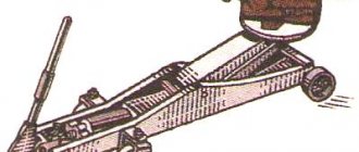
Short walker
Actions on your own, you only have to purchase the necessary parts and ordinary consumables. If you contact a car service, the minimum cost of the service will be 800-1000 rubles. That is, the savings are obvious.
The curtain itself costs about 400 rubles. From here it becomes clear why we did not advise buying a repair kit, but rather completely replacing the part. There will be no savings as such, but the difference as a result of the repair will be significant.
ALL ABOUT CAT
Diagram, device of the VAZ 2110 gearbox. Replacing the airbag, signs of malfunction
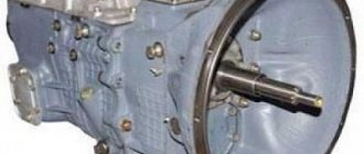
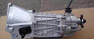
Models VAZ 2113, 2114, 2115 are equipped with a five-speed manual transmission.
"COMPOSITION" of the checkpoint
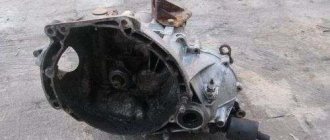
In general, the gearbox on a VAZ consists of two blocks: the housing (it includes the clutch housing and gearbox, as well as the rear cover), and the internal part (gear ratios, differential and main pair).
Let's look at the internal structure of the gearbox. The main pair is the main gear (also called the main shaft of the box). It serves to reduce the speed transmitted by the power unit. The average “performance” of the shaft is a fourfold reduction in the number of revolutions. For example, with a torque of the power unit of four thousand revolutions per minute, the main pair “produces” only one thousand revolutions, respectively.
Another important component of the internal structure of a transmission is the gear ratios. Gear ratios are gears, each of which is responsible for its “own” gear. Cars produced in Tolyatti usually have the following gear ratio parameters:
- 1st: 3.636
- 2nd: 1.95
- 3rd: 1.357
- 4th: 0.941
- 5th: 0.784
- Reverse: 3.53
The main part of the VAZ 2114 gearbox is the rocker (the part is used when changing gears).
Backstage
Developed in the 80s of the last century, the rocker has many drawbacks, including poor “interactivity” when changing gears (gears may not engage the first time, constantly jam, or engage poorly). The speed of gear shifting depends on the length of the link. Typically, sports cars are equipped with a shortened version of the rocker, this allows you to solve many problems with gear shifting and add dynamics to the car. Well, to improve the “controllability” of gears, another part of a similar purpose has long been used: a cable. Thanks to it, you can clearly and quite easily switch to the desired gear.
DISADVANTAGES OF GEARBOX VAZ 2114,2113,2115
In VAZ 2114 cars, there is a loss of dynamics when switching from 1st to 2nd gear. This is due to the fact that the 1st is quite long, but the 2nd, exactly the opposite, is too short. In addition, with frequent sharp gear changes, the 2nd gear synchronizer may fail. Tuned and sports cars VAZ “13,14,15th” series can boast of excellent dynamics. This is due to the fact that the “gap” between “1st” and “2nd” gears is reduced to a minimum.
The drawstring is too long. Because of this, gear shift speed suffers. In addition, the imperfection of the rocker design makes the process of switching gears quite complex and ineffective.
What is a short-stroke link?
The standard rocker on the VAZ 2114 is a very reliable device, and even in the event of any malfunctions, it is easily repaired, is unpretentious to donor parts and creates a general impression of an analogue of a Kalashnikov assault rifle from the world of automobile rockers.
But what is really not pleasing about it is the attitude of the designers towards the comfort of the car enthusiast; perhaps some of them think that clogging the gears with a sweeping click is stylish, but in reality it only distracts from the road. It was to resolve this situation that the short-stroke slide was created.
This engineering idea is not something innovative; this idea came to civil vehicles from the world of sports competitions, where fractions of seconds decide everything. Initially, to reduce switching time and increase its accuracy in sports, boxes with a lever mounted in the gearbox housing were used, but it transmitted vibrations and did not allow the creation of more convenient control methods.
Therefore, a mechanism called a rocker was developed, the task of which was to convey the motorist’s decision to shift the gear forks into the gearbox through racks located outside the gearbox housing. This gearbox control inherited the sweeping switching of the forks from its older brother - the “lever in the body”.
Therefore, this engineering solution was further improved, as a result of which a short-stroke rocker appeared on the VAZ 2114 and other cars.
VAZ 2114 gearbox malfunctions
Gearbox VAZ 2110 5 mortar device diagram
First, it is worth considering faults that can be removed without dismantling. If the reverse gear does not press, it is worth checking the clamp and the mechanism itself for blocking. Another common problem is a rattling gearshift lever. The sound comes from a bushing that hits the surface of the wings. You can solve a manufacturing defect using a file - the error is determined and excess metal is removed.
Repair and, accordingly, removal of the gearbox is required when, when changing gears, a grinding or crunching sound appears in the gearbox, a hum is heard, and the lever moves with difficulty. Also, dismantling is indispensable when some gears are switched off randomly (the problem is caused by a drive adjustment failure or a synchronizer failure).
Sports
We noted that for the VAZ 2114 you can install a sports short-throw rocker . Outwardly they are quite similar, but the difference in work is felt immediately. On a sports unit, gears shift faster and smoother. It's all about the design of the backstage itself. Unfortunately, it is precisely because of this that the process of independent replacement becomes almost impossible.
Sports model
4 / 5 ( 1 voice )
Removing and installing the gearbox of a VAZ 2115 - 14
Removal
Place the VAZ 2115 - 14 car on a lift or inspection ditch. Raise the engine hood and lock it in this position. Next, follow these steps:
-disconnect the wires from the battery, from the starter traction relay
-disconnect the ground wire from the clutch housing
- disconnect the lower part of the clutch cable
- unscrew the two upper bolts securing the clutch housing to the engine block and the two upper nuts securing the starter, attach a bracket for lifting the power unit to the left stud of the engine exhaust manifold
Fig. 1 Installing a cross member to support the power unit
-install a cross member on the gutters to support the engine and hook it to the bracket installed on the exhaust manifold stud. If there is no cross member, hang the power unit with a hoist.
Next, perform work on the bottom of the car:
-remove the engine splash guard and the lower clutch housing cover
- drain the oil from the gearbox
-disconnect the wires from the reverse light switch
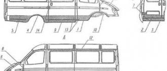
Fig.2 Mounting the gearbox on the car
1-engine, 2-power unit mounting bracket, 3-extension arm suspension bracket, 4-extension arm, 5-gearbox, 6-wheel drive shaft, 7-suspension arm, 8-anti-roll bar, 9-rear power unit support , 10-clamp, 11-rod gear lever drive, 12-inner joint housing
- loosen clamp 10 (Fig. 2) and disconnect rod 11 from the gear selection rod hinge
- unscrew the nut of the stud securing the gearbox to the engine
- disconnect the ball joints of the suspension arms from the steering knuckles
- using a puller or sharply hitting the body 12 of the internal joint with a hammer through a drift, knock out one hinge from the side gear, then fix the side gear with a technological mandrel or plug used when transporting the differential (otherwise the unfixed side gear may fall into the gearbox housing), after which knock out the second hinge
- move the wheel drive shafts to the sides
- unscrew on the left side the three nuts of the studs securing the gearbox to bracket 2 (Fig. 2) of the power unit suspension, and then the nut from the bolt securing the bracket itself. Having removed the bracket from the gearbox studs, remove the suspension bracket 2 from the eyelets of the body side member
- unscrew the bolts securing the rear support 9 of the power unit suspension
-unscrew the lower nut securing the starter and remove it
-install a special stand with a hydraulic lift under the gearbox
-lower the engine slightly by extending the support rod of the cross member or lowering the hoist, unscrew the lower bolt securing the crankcase to the engine block and move the gearbox assembly with the clutch housing away from the engine to separate the gearbox shaft and the driven clutch disc
-remove the gearbox
Installation
Install the gearbox in reverse order, taking into account the following:
- before connecting the wheel drive shafts with the side gears, replace the retaining rings on the internal joints with new ones, since when installing old rings, spontaneous separation of the wheel drives and side gears is possible when the car is moving.
- before installing the gearbox, apply a thin layer of CV joint-4 grease to the outer surface of the guide sleeve 2 (see Fig. 1 chapter “VAZ 2115-14 car gearbox”) of the clutch release bearing clutch. If necessary, center the driven disk with a mandrel
Fig.3 Centering the driven disk
1-flywheel, 2-clutch assembly, 3-mandrel
After installing the gearbox, adjust the full travel of the clutch pedal (see the chapter “Clutch of a VAZ 2115-14 car”) and the gear shift control drive in the following order:
- working from below the car, with the clamp bolt 13 loosened (see Fig. 2, chapter “Gearbox of the VAZ 2115-14”) of the rod 8, set the rod 6 to the neutral position
- set lever 10 to the required position
- working from the bottom of the car, select the axial play in the rearward direction, acting on the hinge 7 and the angular play in the counterclockwise direction, tighten the nut of the coupling clamp 13, having previously installed it at a distance of X = 1-3mm. Select the backlashes with a light movement so as not to cause movement of the selector levers inside the gearbox. Then fill the gearbox with oil.
When connecting the gearshift drive to the gearbox, make sure that there is no twisting or deformation of the corrugations of the protective cover of the hinge 7.
Dismantling
All gearbox repair work involves its removal. They pass on an overpass (you can park the car over the pit). For dismantling you will need a set of keys and screwdrivers. If possible, it is better to carry out dismantling together. This speeds up the process significantly.
- The power is turned off and the battery is removed. The oil is drained from the box and the starter is removed. The wires and protection are removed from the unit and 2 nuts from the bottom and one nut from the surface of the starter are unscrewed.
- The connecting cable between the clutch release fork and the gearbox is removed.
- The wires on the speed sensor are disconnected.
- The reverse sensor wires are disconnected.
- Remove the torque rod bracket bolts.
- Jet thrust is removed.
- The wheel drives are dismantled. The left wheel drive is completely removed. The right wheel drive is disconnected and placed next to the gearbox on the housing.
- Remove the bolts securing the steering knuckle from the left ball joint.
- The gearbox mount to the engine is dismantled. On the lower right side, the brackets are removed from the studs.
- Remove 3 bolts of the housing cover from the clutch housing.
- The bolt is unscrewed from the lower left gearbox mount.
- Unscrew the engine fixing nuts from the left and rear supports.
- The bolts securing the gearbox to the rear engine mount are unscrewed.
- The rear engine mount is removed.
- The box moves backwards from the guides. To do this, place a screwdriver in the hole between the cylinder block and the clutch housing and, pressing, move the gearbox. The rear part of the gearbox should go above the suspension extension, the input shaft should be disconnected from the clutch.
- The box of the VAZ 2114 is carefully removed from the car.
VAZ 2114 gearbox repair
Disassembling the VAZ 2115 gearbox
Wash the gearbox, preventing water from entering the crankcase, and place it on a disassembly stand. Remove the power unit suspension bracket and the clutch release cable mounting bracket.
| Rice. 3.7. Gearbox: 1 – clutch release bearing; 2 – guide sleeve; 3 – input shaft; 4 – roller bearing of the secondary shaft; 5 – secondary shaft; 6 – retaining ring; 7 – satellite axis; 8 – speedometer drive drive gear; 9 – transport plug; 10 – wheel drive oil seal; 11 – tapered roller bearing of the differential; 12 – axle gear; 13 – satellite; 14 – differential box; 15 – clutch housing; 16 – driven gear of the main gear; 17 – drain plug; 18 – adjusting ring; 19 – driven gear of the 1st gear of the secondary shaft; 20 – synchronizer for 1st and 2nd gears; 21 – driven gear of the second gear of the secondary shaft; 22 – retaining ring; 23 – persistent half ring; 24 – driven gear of the third gear of the secondary shaft; 25 – synchronizer for 3rd and 4th gears; 26 – driven gear of the fourth gear of the secondary shaft; 27 – needle bearing of the secondary shaft gears; 28 – ball bearing of the secondary shaft; 29 – thrust plate; 30 – driven gear V of the secondary shaft transmission; 31 – 5th gear synchronizer assembly; 32 – nut; 33 – thrust washer; 34 – drive gear V of the input shaft; 35 – rear cover of the gearbox housing; 36 – ball bearing of the input shaft; 37 – gearbox housing; 38 – roller bearing of the input shaft; 39 – breather; 40 – input shaft oil seal |
After unscrewing the nuts, remove the back cover 35 (see.
| Rice. 3.12. Removing the primary and secondary shafts |
Remove the primary and secondary shafts at the same time (
| Rice. 3.13. Removing the gear selector mechanism |
Unscrew the gear selector mounting bolts (
| Rice. 3.14. Secondary shaft parts: 1 – nut; 2 – thrust plate; 3 – sliding clutch of the 5th gear synchronizer; 4 – sliding coupling hub; 5 – synchronizer blocking ring; 6 – 5th gear gear; 7 – distance ring of the needle bearing; 8 – needle bearing; 9 – 5th gear gear bushing; 10 – thrust washer; 11 – ball bearing; 12 – thrust washer; 13 – 4th gear gear bushing; 14 – 4th gear gear; 15 – sliding clutch for synchronizer of 3rd and 4th gears; 16 – sliding clutch hub; 17 – third gear gear; 18 – retaining ring; 19 – thrust half-rings of the secondary shaft; 20 – 2nd gear gear; 21 – sliding clutch for synchronizer of 1st and 2nd gears with reverse gear; 22 – retaining ring of the synchronizer hub; 23 – hub of the sliding clutch for the synchronizer of 1st and 2nd gears; 24 – synchronizer spring; 25 – cracker; 26 – retainer; 27 – 1st gear gear; 28 – roller bearing |
If it is necessary to disassemble the secondary shaft, clamp it in a vice with soft pads and use a universal puller to press the ball bearing from the shaft. The bearing is pressed off the input shaft in the same way. Then remove the driven gears of IV, III, II and I gears and synchronizers assemblies from the secondary shaft in the order indicated on
| Rice. 3.15. Differential assembly: 1 – satellite axis; 2 – retaining ring; 3 – semi-axial gears; 4 – speedometer drive drive gear; 5 – differential box; 6 – satellite; 7 – driven gear of the main drive |
– if it is necessary to replace the driven gear, unscrew the bolts securing it and compress gear 7 (
| Rice. 3.16. Details of the gear selection mechanism: 1 – gear selection rod; 2 – gear selection rod lever; 3 – housing of the gear selection mechanism; 4 – three-arm gear selection lever; 5 – blocking brackets; 6 – axis of the gear selection lever; 7 – guide axis of locking brackets; 8 – reverse fork; 9 – clamp; 10 – thrust washer; 11 – spring |
If necessary, disassemble the gear selection mechanism by unscrewing the nut securing axle 6 (Fig. 3.16) of the gear selection lever and remove the retaining rings from the reverse fork axle and from the axle 7 of the locking brackets, remove the reverse fork 8, gear selection lever 4 assembly with a locking bracket 5, a lever axis 6 and a spring 11 with a thrust washer 10.
If necessary, remove the speedometer drive by unscrewing the nut securing it and, supporting the driven gear shaft, remove the speedometer drive.
Video about “Disassembling the gearbox” for VAZ 2115
repair and disassembly of the VAZ 2114 box
Repair of VAZ 2115 (2110,2111,2112) gearbox. Disassembly of gearbox
disassembly of the VAZ 2108-2114 gearbox
Removing the gearbox from a VAZ 2113, VAZ 2114, VAZ 2115
How to remove the gearbox from a VAZ 2113, VAZ 2114, VAZ 2115? This question may arise in a number of cases, whether it is replacing a clutch disc, clutch basket, release bearing, or replacing a flywheel ring. And there are many other reasons for the need to remove the gearbox. In this regard, this procedure is included in a separate article. Removing the gearbox is a thorough process and you need to prepare for it properly. You will need: a lift or pit, a set of socket wrenches (sizes: 30, 19, 17, 13, 10), a flat-head screwdriver, a mount………….. After preparing all of the above, you can proceed directly to removing the gearbox. First of all, remove the terminal from the battery. The air filter will interfere with us, so use a 10mm wrench to unscrew the air filter mount. We disconnect the mass air flow sensor and move the filter to the side, along with the pipe.
It would be enough. Using keys 13 and 17, disconnect the power supply to the starter and unscrew one bolt (indicated by the upper right arrow (the rest will be more convenient to turn from below) securing the starter itself.
Unscrew the two nuts securing the gearbox to the engine. Use a 17 key to disconnect the clutch cable.
Next, we hang up the car and take off the front wheels. Use a 30mm wrench to unscrew the hub nut, having previously loosened it.
At the same time, it is necessary to keep the brake pedal depressed. And not weakly, because as a rule the hub nuts are tightly tightened. Further actions will take place under the car. The next step is to remove all the protection available under the engine compartment.
If you need to remove the drive, in order to protect against possible leaks, you need to drain the oil, for which you unscrew the bolt-plug with a 17mm wrench. Here we will consider the option without removing the drives from the gearbox. After the engine protection is removed, you need to use a 17mm wrench to unscrew the three bolts securing the crabs.
Using the key again at 17, unscrew the stabilizer mounts.
Using the same key, unscrew the two bolts securing the ball joints.
After carrying out these procedures, you can pull out the drive. To do this, it is necessary to remove the drive from the hubs on each side by simply moving the hub to the side.
Disconnect the reverse switch. Disconnect the speedometer terminal.
Now we remove the starter by unscrewing the remaining two bolts (let me remind you that one bolt on top has already been unscrewed) securing it.
From the rear, on the interior side, a rod approaches the gearbox (the rod comes from the gear shift lever). This rod will be connected to the gearbox rod through a clamp tightened with a bolt and nut size 13. We loosen this clamp and pull the rod off the splines of the rod.
So, using a 10mm wrench, unscrew the three bolts securing the flywheel protection, the so-called crescent.
Unscrew the side airbag fastening. And the rear cushion is attached to two studs. And finally, we unscrew the remaining two bolts (the first bolts, let me remind you, we unscrewed them from the top) securing the gearbox to the engine. After the work has been done, the gearbox can be removed, first by hooking it with a pry bar.
The box must be removed carefully, especially without damaging the petals on the clutch basket with the input shaft. Box removed
Its installation is carried out in the reverse order of removal. When the process as a whole is clear, the sequence of some steps can be changed, depending on what is convenient for you. In addition, it should be noted that after installing the box in place, it will be necessary to adjust the travel of the clutch pedal by moving the clutch cable to a certain position using the corresponding nuts.
Types of gearboxes (speeds)
Currently, there are 3 types of gearboxes in cars:
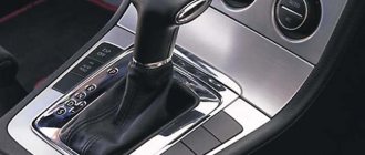
- mechanical, speeds are switched manually using a special lever;
- automatic, in which the gear change occurs without external influence, but only when the gas or brake pedals are pressed. Reverse gear in such cars is activated manually.
- mixed (variable). In this type, the gearbox operates in automatic mode, but under certain conditions it can be briefly switched to manual control.
The most popular because of maintenance, ease of replacing parts and inexpensive repairs is the manual gearbox. It is divided into 3 subtypes: 4-speed, 5-speed and 6-speed. Five speeds for the gearbox are familiar and are the most common.
Transmission oil viscosity, what viscosity is needed
“All-season” oils GL 4 or GL 4/5 with a viscosity of 75W-80 or 80W-85 are considered good for use for front-wheel drive VAZ cars.
Gear Features
The highest torque of the car is at first speed. It is not difficult for the engine to rotate the wheels, but the speed of the car will not exceed 40 kilometers per hour. When such a speed is reached, the tachometer needle is usually in the red scale. Therefore, for further movement it is necessary to switch to a weaker but faster gear. Then to the third, quadruple and so on. All switching must be done sequentially. The engine power is not enough to confidently accelerate the car at 20 kilometers in 3rd gear. Unless, of course, it's a 5.0-liter V-8.
In our case, this is a VAZ 14th model, and for normal acceleration dynamics you need to sequentially switch speeds, reducing the gear ratio. The fastest is “fifth”. The load on the engine is minimal here, hence the low fuel consumption. If a car spends 11-13 liters in the city, then on the highway this figure will not exceed seven. But this transmission has one drawback. It has virtually no torque. It will take a long time for the engine to gain speed further. Therefore, when overtaking, it is better to use a “reduced” speed, in our case it is “straight”, fourth speed.
Transmission VAZ 2114
The transmission diagram of VAZ cars is quite simple. It includes clutch, gearbox and front-wheel drive. The device that is the first in the transmission chain between the internal combustion engine and the wheels and receives torque from the engine is the clutch. On this machine it is single-disk, dry, closed, with a pressure spring and a damper on the driven disk. The drive is a cable drive, with no gap between the bearing and the pressure spring. It is controlled by a pedal mounted on the same axis as the brake pedal.
The normal pedal travel from the top position to the stop on the floor mat is 135 millimeters. During operation and as the driven disk linings wear out, this stroke can increase and reach 160 mm. This is considered acceptable, but it is not recommended to exceed this distance; a situation is possible when the clutch begins to “drive” due to poor contact between the drive and driven discs.
In this case, it is recommended to adjust the clutch, which you can do yourself. To do this, it is necessary, in the engine compartment of the car, on the tip of the clutch drive, to rotate the nut, controlling the pedal stroke; when the desired result is achieved, you need to tighten the lock nut, thereby fixing the desired position of the pedal.
The final part of the VAZ 2114 transmission is the front wheel drive. For each wheel there are two angular velocity joints, external and internal. They are driven through the wheel drive shaft. On the right wheel it is made of a pipe, and on the left - from a rod. If they fail, the angular velocity joints cannot be repaired; they must be completely replaced.
Oil with high viscosity, why you can’t fill in oil with high viscosity like 5W-50
It is strictly not recommended to fill the gearbox with oil with a viscosity index of 85W-90, much less 5W-50 motor oil. Increased viscosity can create a strong oil film that is difficult to penetrate between the gears and their teeth. Synchronizers especially suffer, since they have to squeeze out dense oil from under them, and their design is not designed for these mechanical forces.
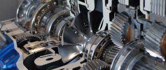
VAZ 2114 gearbox device
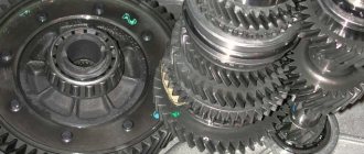
The main working unit of the transmission is the gearbox, in which all the main parts are rotating shafts, gears and transmission links that experience constant friction and require effective lubrication. This oil is special and is called transmission oil according to the place of application. To understand which gear oil is best for the VAZ 2114, you need to understand the structure of the VAZ 2114 gearbox.
VAZ 2114 gearbox device
The following requirements apply to the gearbox, as well as to the entire vehicle transmission:
- all transmission units must provide high speed and good traction when driving both in a straight line and when turning;
- they must provide simple and easy control while driving in order to minimize driver fatigue;
- small size and weight are one of the main requirements, because designers are fighting for every gram of weight and millimeter of volume, to lighten the overall design while increasing power and efficiency of its use;
- high reliability during operation, no one needs a unit that will have to be constantly maintained;
- each unit individually and the transmission as a whole must have a high efficiency;
- simplicity in design must be accompanied by simplicity and high manufacturability in production so that the product is economically profitable;
- after installation on the vehicle, all transmission units must be easily accessible and convenient to maintain throughout the entire period of operation;
- An important requirement is to ensure silent operation of the system.
The VAZ 2114 gearbox device meets all these requirements. This mechanism is designed to change the drive torque and wheel speed within wide limits necessary to ensure vehicle movement over the entire speed range determined by its technical characteristics. In addition, it ensures that the machine moves backward and idles for a long time.
The VAZ 2114 gearbox has five stages, synchronized. The box is connected to the differential, as well as to the main gear. The input shaft is made of a block of gears of the first, second, third and fourth gears with a mounted fifth gear drive gear. The secondary shaft collects all the driven gears and is itself connected to the drive gear of the main transmission. The gearbox control drive includes:
- gear lever;
- rod and ball joint;
- gear selector rod;
- gear selection and shift mechanism.
Work principles
Old box with modernization
The new design is the old gearbox with significant upgrades. The previous design is known to us for its shortcomings: large lever strokes, difficult activation and low vibration comfort.
The cable driven gearbox is not a new type. The device can be safely called an updated version of the previous design, which has been made more convenient by improving it. It follows from this that the driver, accustomed to the previous version of the box, will not need to relearn. For cable gearboxes, the diameter of the clutch has been changed, increased from 200 to 215 mm. The starter was moved, installing it along the engine.
Two cables, when interacting with the box, will dampen the transmitted vibrations. This will make the shifting smoother and also reduce the travel of the gearshift knob. The cable design allows shifts to be crisp rather than harsh. In addition, the travel of the shift lever has been significantly reduced. Cable drive is superior to other design solutions in terms of seasonal changes in weather. As a result of replacing the traction drive with a cable drive, the amount of oil poured decreased by 30% due to the transfer of the gear selection mechanism to the top from the bottom.
Severe frost helps the butter thicken. A conventional gearbox requires a lot of effort to start the engine. But the cable mechanism eliminates this problem because the shift mechanism is not submerged in oil, as it is located on top.
The use of a cable drive helps to significantly reduce longitudinal movement - up to 13 cm, and transverse movement - up to 9 cm. The design is made reliable and maximally optimized. This type of gearbox is good for cars with high power engines. Since the clutch has been increased, its torque is quite high.
Box with upgrade
Shift quality and machine vibration comfort
The gearbox is a complex unit. According to many car enthusiasts, changing gears is not an easy operation. Over time, each driver gains experience in driving a car. But during the adaptation period, a huge load falls on the transmission. Drivers who lack confidence often forget to press the pedal when changing gear.
The design of the box makes it possible to have less impact on the box itself due to the reduced number of strokes. In addition, the possibility of oil leakage is eliminated. Car manufacturers believe that this box option will not affect the cost of the car.
Reviews of the updated gearbox confirm the fact that it is silent when starting the engine and when releasing the clutch. Car enthusiasts talk about easy start-up and lack of vibration. Many users agree that it is now pleasant to change gears. In reviews, some motorists point out that almost nothing has changed in the movements of the lever, but it does not dangle and clicks quietly due to the absence of play in the drive.
Gear shifting efforts have been significantly reduced. According to those who are already using the new gearbox, there is a small drawback: you have to stretch a little for 5th gear, and sometimes the reverse gear is not engaged. But in general, the updated transmission significantly improves the quality of shifts and vibration comfort of the car.
Updated transmission
Diagnostics and minor repairs of the device
The gearbox, like many car components, sometimes malfunctions and requires maintenance. There are several main reasons that lead to problems. If you hear extraneous noise in a VAZ gearbox, it may be due to wear on the gear teeth or bearings. The box may make noise if the oil level is low. To solve the problem, it is necessary to replace worn mechanisms, oil seals and bring the oil level to normal.
Problems when shifting gears. In this case, it is necessary to inspect the control drive rods for wear. You should check the reliability of the hinge mounting and the gearbox lever rod. Incorrect debugging of the switching drive or breakdown of plastic parts of the assembly can also cause a similar problem. To troubleshoot problems, you need to adjust or replace the rod, tighten the screws and adjust the drive, and replace faulty parts.
Spontaneous gear reset is possible when the end teeth on the clutch itself or gears wear out or fail. This is also possible if the drive is adjusted incorrectly or the protective cover of the thrust is installed inaccurately. The problem can be corrected by replacing unusable parts, debugging the drive, and mounting the cover in the desired position. If there is an oil leak, secure the crankcase and replace worn gaskets. For future repairs to the box itself, it must be removed. The process must be carried out in this sequence.
- Unplug the box.
- Drain the oil and disconnect the starter.
- Remove the crankcase protection.
- Disconnect the fastening cable and remove it from the bracket.
- Remove the wires by pressing the spring.
- Remove the reverse control wires.
- Unhook the rod from the hinges, moving it back a little.
- Remove the clutch cover.
- Hold the box and unscrew the remaining nuts.
Malfunctions and their elimination
Gearbox repair largely depends on the nature and type of fault. There are several options for the breakdown of this unit, in each of which appropriate actions should be taken to eliminate them.
Malfunction
Possible reasons
What do we have to do
There is noise in the gearbox
- The teeth on the gears are worn out;
- Bearings are worn out;
- The oil level in the gearbox has decreased
- Add oil;
- Replace worn bearings;
- Replace seals if necessary
Gears are difficult to shift
- The clutch is not fully depressed;
- The rod that controls the gear shift mechanism has become deformed;
- The integrity of the jet thrust has been compromised;
- The joint or rod that selects the gear is loose;
- The speed change drive is incorrectly adjusted;
- The plastic components of the gear shift drive are broken
- Try straightening the rods. If this is not possible, replace them;
- Tighten the mounting screws more tightly;
- Adjust the gear shift drive;
- Replace damaged components
Spontaneous gear disengagement occurs
- The ends of the synchronizer teeth on the gear and clutch are damaged or worn;
- Cracks appeared, the rubber on the rear supports delaminated;
- The gear shift drive was adjusted incorrectly;
- The traction guard was not tightened correctly, which is why the gear is not engaged completely
- Replace worn, deformed elements;
- Correct the position of the rod casing;
- Adjust the drive
Gears are switched on with noise and crackling
- The clutch does not disengage completely;
- The locking ring of the gear synchronizer, which is engaged, is worn out
There is an oil leak from the gearbox
- Wear of the input shaft oil seal; Wear of the rod
- speed selection;
- Breakage of the speedometer drive shaft seal;
- The cover on the gearbox or crankcase is loose;
- The sealant under the gearbox cover is damaged;
- The drain hole closure is loose
- Replace gaskets, use new sealant and gaskets;
- Tighten all existing fasteners;
- Check the condition of the drain plug
In most cases, problems with the gearbox are eliminated by dismantling and disassembling it. Do not take on this type of work without the proper skills and experience.
Preparing for removal
Preparatory work includes the removal of all parts that block access to the gearbox. You can begin removal when you have a board or other hanging equipment, a set of wrenches and sockets, different types of screwdrivers, and WD-40 lubricant at hand. It is also recommended to carry out work in a garage where there is a car pit. Now you can proceed to the analysis:
- It is necessary to remove the terminals from the battery and then remove it. The next step is to completely remove the working fluid from the gearbox and remove the starter. Some bolts may not budge, in which case WD-40 must be used;
- Now the VAZ 2114 needs to be placed on the pit and the crankcase protection, which is attached to the bottom with three fasteners, removed;
- There is a cable coming from the clutch fork - it should be disconnected from the fork and then removed from the gearbox bracket;
- Next, you need to hang the motor to gain access to the lower parts. After this, all wires must be disconnected from the speed sensor. A spring is used as fastening here.