Cleaning the crankcase ventilation system on VAZ 2113, VAZ 2114, VAZ 2115
Welcome! Crankcase ventilation system - it is present in many gasoline cars, due to it the environment is not heavily polluted and all exhaust gases are sent back to the car engine for combustion; in old cars, people themselves modify this system in such a way that all the crankcase ventilation hoses go outside (And this is all due to the fact that the engine begins to release contaminated crankcase gases and if they fly back into the engine, they will simply choke it), because of this, the environment suffers, we immediately warn you, but the engine’s power increases and it It will be much easier to breathe.
Note! To clean the crankcase gas system, you will need: Screwdrivers, all kinds of wrenches and pliers!
Summary:
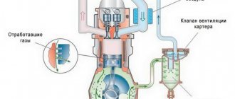
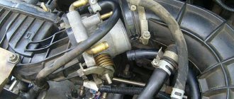
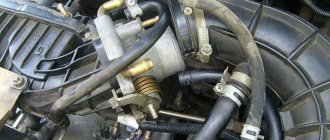
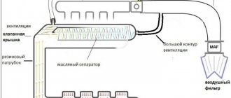
Where is the crankcase ventilation system located? This system consists of two hoses (Indicated by arrows) and a filter that passes all dirty air and oil particles through and thereby cleanses all the air of this rubbish, the filter itself is located in the valve cover (Location is indicated by a green arrow), in more detail if If you want to see it, look at the small photo, it is made in the form of a grid pack.
Note! The principle of operation of the ventilation system is this: when the engine is running, the mixture burns and for the most part everything goes into the exhaust pipe, but still, a little bit through the piston rings, vapors break through and in this case the ventilation comes into operation, due to it these vapors come out first along the lower ventilation pipe (Indicated by a blue arrow in the photo above), then they are cleaned by a filter and pass in purified form to the upper hose, the hose of the small ventilation branch (Indicated by a red arrow), and thus these unburnt vapors fly back into the car engine, to re-combustion, that’s how the ventilation system works!
When should you clean the crankcase ventilation system? When the filter becomes clogged with dirt, when the hoses become clogged, all this dirt begins to fly into the engine, so that the dirt does not fly, you need to periodically wash the filter and clean the hoses inside with a cloth, the frequency of this depends on how worn out the engine is, in new engines the first 50 thousand in general There’s no point in even getting into the crankcase ventilation system, because the rings on the pistons are intact and there’s not a lot of vapor breaking through them into the system. On used engines, we recommend it more often, since this operation is not long and there is no harm from it, only benefit ( The factory calls the figure 60,000 thousand kilometers, this is a lot, if you treat your car well, then clean the system much more often, once every 30,000 thousand kilometers approximately).
avtoexperts.ru
Among various auto systems, the crankcase ventilation system plays a significant role in the formation of the air-fuel mixture, stable and economical operation, full power delivery, protection of engine oil and extension of the life of the cylinder-piston group.
In the design of a car, the crankcase ventilation system is the “lungs” of the engine, necessary for its normal functioning. The system is called PCV (Positive Crankcase Ventilation). However, it is the one that is undeservedly given a minimum of attention and maintenance, and many car owners do not even know about its existence. In this article we will try to understand why this system is needed, how it works, its inherent faults and methods for checking its performance.
What are “crankcase gases”?
During combustion, the fuel-air mixture sharply increases in volume, creating enormous pressure inside the combustion chamber. The expanding gases from combustion force the piston to bottom dead center, causing the engine crankshaft to rotate. Some of the gases penetrate through the leaks between the rings and the cylinder mirror into the oil pan, where, mixing with oil vapor, they create pressure that aggressively affects the crankshaft seals and the pan gasket, and the oil dipstick channel.
The expansion stroke is repeated in each cylinder, constantly pumping the next portion of gases into the sump, and if the crankcase ventilation does not work, the gases will either squeeze out the crankshaft oil seals, or “knock out” the oil dipstick and expel the oil from the crankcase, with all that follows.
In addition, particles of unburned fuel, small fragments of soot, and moisture vapor are transferred to the sump along with the gas, which are mixed with the engine oil located in the engine sump. This, in turn, leads to oxidation of the oil, clogging it with wear products, reducing its performance properties and reducing its service life.
System design
In order to minimize the impact of gas pressure, the engine design provides crankcase ventilation systems. Modern cars use a closed ventilation system, which is necessary to comply with environmental standards.
Despite the differences in systems on different brands of cars, they all have three common components, such as:
• Air pipes for removing gases from the crankcase;
• Ventilation valve, responsible for regulating the gas pressure;
• An oil separator that cuts off oil vapors as gases exit the engine sump.
The valve opens when excess pressure appears and closes when there is a vacuum, that is, the principle of its operation is based on the difference in pressure behind and in front of it.
The separation of oil particles is carried out by the passage of gases through a system of labyrinths, vortices and grids in oil separators. The separated oil then flows back into the engine sump. This not only saves oil, but also protects engine parts from carbon deposits. In this case, oil separators can be located inside the valve covers, built into the engine, or made as a separate unit.
Principle of operation
The system works as follows. The ventilation pipe is connected to the intake manifold, where immediately after starting the engine, a vacuum is created, due to which crankcase gases are “pulled” from the pan and passing through the oil separator enter the intake, where, mixing with the incoming air, they enter the combustion chamber and burn out.
Advantages of the ventilation system
The use of crankcase ventilation allows you to reduce the percentage of harmful emissions into the atmosphere, reduce engine oil waste, and maintain stable engine speeds when warming up, since the intake air mixes with crankcase gases and heats up, which generally has a beneficial effect on the operation of the power plant.
Flaws
Despite the presence of an oil separator, the air ducts and intake elements become dirty from the passage of crankcase gases, causing frequent failures of the devices during operation. So, on gasoline car models, the throttle valve assembly and idle speed control become coated, since they have special channels that perform an exhaust function. This can also be observed on carburetor models, for example, with a Solex carburetor equipped with a fitting for crankcase ventilation.
The throttle valve assembly and gas exhaust valve on carburetors are the so-called small branch and are activated when the vacuum in the air filter is insufficient.
Symptoms of a PCV Problem
• The appearance of traces of oil in the air filter;
• Fogging of oil seals and the joint of the engine valve cover;
• Smoke from the exhaust due to oil particles and gases entering the combustion chamber;
• Traces of oil around the filler cap and on the valve covers.
How to clean the crankcase ventilation system on a VAZ 2113-VAZ 2115?
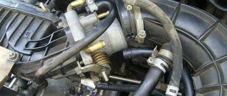
1. First, remove the hoses, which ones specifically relate to the crankcase ventilation, we already said at the beginning of the article, so you will need to remove them and wash them inside and wipe them with a cloth (The hoses are easy to remove, they are secured with clamps), if the hoses are all cracked, we recommend them replace with new ones.
2. Now disconnect the tip of the throttle cable from the throttle assembly sector, you will find more details on how to do this in the article entitled: “Replacing the throttle cable”, there will be point 1 and there are 4 photos in it, you need exactly 2 and 3 and Read the description for them.
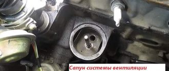
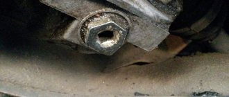
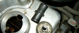
Next unscrew the two nuts that secure the cylinder head cover (see photo 2), remove the metal washers and rubber bushings underneath them (see photo 3) and finally, remove the cover itself from the cylinder head.
Note! Check the removed rubber bushings and, if necessary, replace them with new ones if they are torn or lose their elasticity; in addition, under the block head cover that you have removed, there will be a rubber gasket; in any case, it must be replaced with a new one, even if the old one is still in your opinion I think it's in good condition!
Diagram of the standard crankcase ventilation system
The crankcase ventilation system of VAZ engines consists of two circuits that operate at different load modes and speeds:
- The small ventilation circuit is connected to the valve cover and the intake manifold (behind the throttle body). This connection diagram provides intensive crankcase ventilation due to the vacuum that occurs in the intake manifold when the throttle is closed. To avoid an effect such as hyperventilation, the cross-section of the small circuit is limited by a jet in the cable throttle body with a diameter of 1.7 millimeters. This circuit operates in the region of 800-1500 rpm.
- A large ventilation circuit is connected to the valve cover and the air pipe (in the pre-throttle space). This scheme provides intensive crankcase ventilation at high speeds. The cross section of the large contour is 16-18 millimeters
Examples demonstrating the shortcomings of the standard crankcase ventilation system:
- A car is going down a hill with the gear in gear. In this mode, the engine operates at higher speeds with a reduced load. A high vacuum is created in the crankcase, and a large ventilation circuit is connected, in which there are no control valves. Since both circuits are connected to one volume of the oil trap, a strong vacuum in the crankcase will draw a fresh portion of air bypassing the throttle. The mass air flow sensor will show increased air flow, and the ECU will try to close the throttle. Having realized that this is not possible (it is already closed), the lean mixture will be corrected by increasing the fuel supply (fuel consumption will increase). As a result, the entire internal volume of the engine will work as a parallel receiver of very significant volume, connected to the intake, bypassing the throttle. It is this volume that will interfere with the formation of a high-quality mixture.
- A car in a traffic jam drives under tension with additional consumers (for example, the air conditioner is on). The compressor clutch is connected, the load increases abruptly. The engine does not have enough air, it begins to pull it from the crankcase, bypassing the throttle. But the ECU is also aware of the clutch engagement and also supplies more air by opening the throttle. The vacuum drops sharply, the vacuum brake booster (VBR) does not have enough strength to hold the car. Leap forward. The ECU sees an increase in oxygen and closes the throttle. A sharp increase in vacuum, VUT seizes. The car jerks, the transmission hits. And so on ad infinitum.
As a result, in both cases, when the engine is running, speed jumps occur and the engine choke under the load. Jerking and vibration are possible on manual transmissions, automatic transmissions and automatic transmissions. To eliminate these shortcomings, it is proposed to modify the design according to one of the presented schemes.
The role of the oil separator
An oil separator, often called an oil sump, is designed to capture large and fine oil particles. Its role is extremely important for the proper operation of the mass air flow sensor (MAF). As oil mist settles on the walls of the intake tract, it quickly becomes covered with dust. Because of this, the operation of the flow meter’s sensitive element is disrupted. The engine control unit receives incorrect readings about the amount of air entering the intake tract. Therefore, forced crankcase ventilation of a modern engine may include several types of oil separators.
Labyrinth oil trap
When gases move through the labyrinth, large oil particles under the influence of inertial forces are pushed towards the walls of the oil separator. The oil flows by gravity through the separator plates into the pan. An oil trap similar in operating principle, consisting of a set of plates, is installed in the valve cover of VAZ injection engines.
Cyclic oil trap
Designed to capture fine particles of oil suspension. As crankcase gases pass around the circumference of the oil separator housing, oil droplets move outward, settling on the walls of the oil separator housing.
Oil separator with filter element
Filter paper or fiberglass filler is installed inside the housing. Passing through the filter, the oil is retained on the walls of the filter element, after which it flows into the pan.
Turbulence of exhaust gas flows moving through the crankcase ventilation hose impairs the uniform filling of the cylinders. Therefore, many cars have an additional sedation chamber installed. In addition to a gas flow retarder, the chamber also acts as an additional oil separator.
Schemes for upgrading the crankcase ventilation system
Schemes for modifying the crankcase ventilation system, as well as a description, are provided by IgorRV.
For LADA cars with manual transmission and AMT (“robot”), scheme No. 1 “Crankcase ventilation scheme with PCV valve for E-GAS and cable throttle” is suitable:
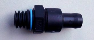
It is necessary to install a PCV valve (article 94580183, price about 400 rubles) from a foreign car into the small crankcase ventilation circuit. When connecting the PCV valve to a small circuit on an E-GAS, use a new hose (petrol-oil-resistant 8 mm without fabric reinforcement). On a cable choke, connect to the receiver, not to the choke.
As a result, the valve will shut off the circuits in transient modes, which will allow:
- Accept the load without jerking or dropping engine speed (for example, when the compressor is running, heated windows, seats, etc.).
- Reduce vibration load at idle
- Increase traction from the bottom (noted by owners of automatic transmission with VAZ-21126 engine, manual transmission with VAZ-21227, 21126 and 11186 and AMT with VAZ-21127).
- Get a sharper response to the gas pedal and faster shifts (on AMT). Perhaps due to the fact that the valve does not allow the engine to slow down, maintaining a more optimal switching algorithm.
- Reduce oil consumption through ventilation.
The valve replacement period is 40,000 km.
For LADA cars with automatic transmission (Jatco) and AMT (“robot”), scheme No. 2 is suitable:
Description of scheme No. 2: The pressure reducing valve is connected in series to a large ventilation circle. Thus, it regulates the flow of crankcase gases at high speeds and during transient processes. This allows:
- Exercise full control over the flow of crankcase gases between the small and large circuits.
- Improve engine operating mode.
- Reduce vibration load.
- Reduce oil release into ventilation.
For LADA cars with automatic transmission (Jatco) and AMT (“robot”), scheme No. 3 is suitable:
Description of scheme No. 3: To improve the operation of the braking system and facilitate the process of holding the car on the brakes in mode “D”, an “Ejection Pump” was used. Due to the flow of crankcase gases from the small circuit, the vacuum in the tube leading to the vacuum booster increases. This happens at low speeds, which is very helpful when driving in traffic jams. Keeping your foot on the brake all the time is not very easy, but this pump makes the task easier.
- Getting rid of vibrations, failures, transmission shocks.
- The engine begins to operate more calmly and softly.
- The force on the brake pedal becomes less.
- The air conditioner turns on almost imperceptibly.
- ejection pump (article 10793 VIKA, price 546 rubles);
- pressure reducing valve (article 1117701500 JP GROUP, 422 rubles);
- PCV valve (article 94580183 GENERAL MOTORS, 400 rubles);
- clamps (about 10 pieces, 600 rubles);
- thin, petrol-resistant 8 mm hose 50 cm (100 rubles);
- standard ventilation pipe.
Installing the PCV valve on Granta
:
Installing the PCV valve on Vesta:
By the way, there are other ways to modify the crankcase ventilation system. Are you ready for such modernizations? Let us remind you that modification of the ignition system (installation of capacitor ignition coils in the harness) is also common among owners of LADA cars.
Source
Breather oil: what to do and how to find the cause
Let's start with the fact that during engine operation, so-called crankcase gases accumulate in the crankcase. To prevent excess pressure from being created, there is a special valve for ventilation. This solution allows the closed crankcase to communicate with the atmosphere. This valve is the breather. In simple words, a breather on an internal combustion engine is actually needed to equalize the pressure inside the engine.
It should be noted that in the crankcase gases mix with oil mist. As a result, lubricant particles enter the breather. Although there is a special oil trap inside the device, a certain part of the oil may escape out. Given this information, minor contamination of the system is acceptable, which is normal. In cases where a lot of lubricant leaks, you should look separately for why oil is leaking from the breather.
On injection engines, traces of oil getting into the throttle area are noticeable, the power unit also loses its throttle response and power, and fuel consumption increases noticeably. It turns out that to check it is necessary not only to inspect the outer surfaces under the hood, but also to remove the air filter, throttle assembly, etc.
Design and principle of operation
As was said at the very beginning, the ventilation system removes crankcase gases from the VAZ 2114 back into the engine, preventing unburned fuel oil mixture from entering the atmosphere. It includes a pair of pipes through which gases are removed, and a filter that traps solid particles and clots.
The whole system functions as follows:
- the fuel mixture entering the engine burns and forms exhaust gases, most of which are discharged from the engine into the exhaust line;
- a small part of the gases leaks through the piston rings and enters the lower pipe of the ventilation system;
- From the lower pipe, gases enter the filter (made in the form of a multilayer mesh), after which, already purified, they return to the engine, where they burn out.
How often should cleaning be performed?
If the ventilation system is clogged and its filter is unable to clean the mixture passing through it, then not only unburned gases, but also oil particles and other pollutants will enter the engine. All this will ultimately have a negative impact on both the operation of the engine and its remaining service life.
The frequency with which the crankcase ventilation of the VAZ 2114 should be cleaned directly depends on the condition of the engine. So, if the car just recently came off the assembly line, and its engine has not clocked up 50,000 km, you shouldn’t even think about cleaning it, since the piston rings are still new, and there is practically no leakage of gases through them.
The first cleaning (as recommended by AvtoVAZ itself) should be performed after the car has covered 60,000 km. And all subsequent cleanings should also be performed after every 60,000 km.
Many owners of domestic cars with extensive experience say that 60,000 km is too much, and cleaning should be done at least every 30,000 km - this will help avoid many problems with the engine and extend its life. In this case, the first cleaning should be carried out after the first 60,000 km.
Necessary tool
To clean the breather on a VAZ engine, check and replace the hoses, you don’t need any special skills or specialized equipment; a standard kit is enough. To complete the work you will need:
- set of keys No. 7-13;
- flat and Phillips screwdrivers;
- washing liquid, kerosene will do;
- container where washing will take place;
- rags;
- breather gasket;
- heat-resistant silicone-based sealant;
- if necessary, a set of new hoses will be required - separately for the carburetor and injector.
This tool can be found in any garage, so there are no problems with its selection. It is better to take rags that do not separate into individual elements, since during washing they can get into the engine.
