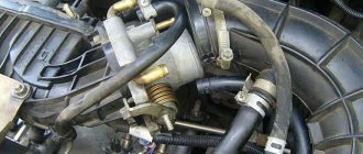
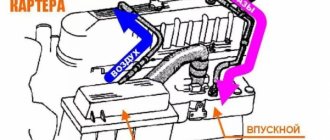
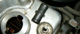
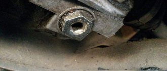
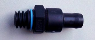
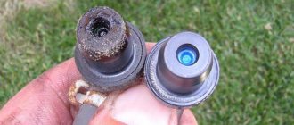
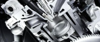
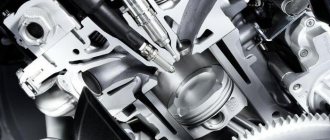
If, while operating a LADA car, you notice that during load (when the air conditioner is running, the heating is on, etc.) in a traffic jam, the engine begins to operate unstably (troits, pulls poorly, etc.), perhaps the reason lies in the ventilation system crankcase The article proposes to solve the problem by installing a PCV valve from a foreign car.
Damage to power plant mechanisms
Damage to the power plant mechanisms responsible for proper mixture formation and oil separation in the combustion chamber (piston scuffing, oil scraper rings, burnout of valves, disappearance of honing, etc.) In this case, the oil enters the combustion chamber of the car, where it mixes with fuel and air vapors, burns out completely. Oil consumption with such a malfunction can be enormous, more than 1 liter per 1 km. Black smoke begins to pour out of the exhaust pipe. This malfunction is caused by driving on a “cold” engine. After 50-60 cold starts, honing sets the oil scraper rings in one direction, the seal is broken and oil consumption increases. The skirt comes off the pistons, the valves burn out, the oil seals become hard. There is only one treatment - engine overhaul.
Purpose of the air filter
Why do you need an air filter at all? It is through this unit that air is drawn in, which is then mixed with fuel and enters the combustion chamber. The filter, in turn, cleans the incoming air flow from dust and dirt.
If this is not done, the parts will wear out much faster, and the issue of engine failure will become a matter of several months. Many car enthusiasts underestimate the importance of filter cleanliness. This is mistake.
A malfunction of this unit or its contamination, at best, can lead to increased fuel consumption and deterioration of vehicle performance, and at worst, to the failure of expensive components of the fuel system or the engine itself.
( 2 ratings, average 4.5 out of 5 )
Operating principle of SVKG
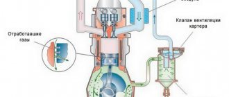
Car engines have a ring gas exhaust system. The resulting gases as a result of the combustion of diesel fuel, gasoline or liquefied gas are not released into the environment, but are returned to the engine, where they are re-burned. The second end of the crankcase ventilation hose is attached to the intake manifold, with the help of which gases again enter the cylinder chamber for combustion. A significant part of the gases, when re-entered, ignite at the moment the fuel ignites, and the remaining ones are released into the atmosphere using the exhaust system. A small percentage of the gases are sent back into the cylinder chamber for re-combustion. This process is ongoing.
Design and principle of operation
Crankcase ventilation systems for different types of internal combustion engines have slightly different structures, but they all necessarily consist of several main parts and assemblies such as:
- air pipes;
- a ventilation valve, the purpose of which is the intensity of gas suction depending on the strength of the vacuum in the intake manifold;
- oil separator
Moreover, regardless of the type of engine, forced ventilation is designed in such a way that its circuit has two parts:
- small branch;
- big branch.
The first one takes gases from under the valve cover, the second one removes unwanted exhaust directly from the crankcase.
The operating principle of the crankcase exhaust system for carburetor, injection and diesel engines can also differ significantly, but the whole process can be described by the following sequence:
- Exhaust gas intake from the engine crankcase;
- Purification of these by-product gases in the oil separator from oil vapors and other mechanical combustion products;
- Transfer of already purified gas through air pipes into the structure of the intake manifold;
- Mixing crankcase gases with the prepared combustible mixture and burning it in the working cylinders.
Due to the possibility of a certain volume of gas entering the constant circulation from point 1 to point 4 and using part of the exhaust gases technologically to prepare the fuel mixture, the selection of exhaust gases from the engine crankcase is also called an exhaust gas recirculation system.
Product delivery options
Note! Below are the shipping methods available specifically for this product. Payment options may vary depending on the shipping method. Detailed information can be found on the “Delivery and Payment” page.
Parcel by Russian Post
Available payment methods:
- Cash on delivery (payment upon receipt)
- Using cards Sberbank, VTB, Post Bank, Tinkoff
- Yandex money
- QIWI
- ROBOKASSA
Shipping throughout Russia. Delivery time is from 5 to 12 days.
Parcel by Russian Post 1st class
Available payment methods:
- Cash on delivery (payment upon receipt)
- Using cards Sberbank, VTB, Post Bank, Tinkoff
- Yandex money
- QIWI
- ROBOKASSA
Shipping throughout Russia. Delivery time is from 2 to 5 days. More expensive than regular delivery by Russian Post, approximately 50%. Parcel weight up to 2.5 kg
Express Parcel EMS
Available payment methods:
- Cash on delivery (payment upon receipt)
- Using cards Sberbank, VTB, Post Bank, Tinkoff
- Yandex money
- QIWI
- ROBOKASSA
Shipping throughout Russia. Delivery time is from 3 to 7 days. More expensive than regular delivery by Russian Post, approximately 100%.
Transport companies
Available payment methods:
- Using cards Sberbank, VTB, Post Bank, Tinkoff
- Yandex money
- QIWI
- ROBOKASSA
Delivery is possible to any locality where there is a representative office of the transport company. Delivery time is from 2 to 10 days. Sending large parcels is approximately 50% more profitable than by Russian Post.
Courier delivery in Togliatti
Available payment methods:
- Cash upon receipt
- Using cards Sberbank, VTB, Post Bank, Tinkoff
- Yandex money
- QIWI
- ROBOKASSA
Delivery time from 1 to 12 hours.
Crankcase ventilation VAZ 2107 injector
It’s time for me to take a photo and post my VF tune, but I still can’t get around to it, because I haven’t been climbing into the carb for a very long time
The point is to transfer the hole in the VF housing from which crankcase gases escape to the outer diameter of the housing. That is, filter crankcase gases along with the incoming air.
True, judging from the dispute below, this approach can suck in dust, which is present in large quantities in front of the filter. But it seems doubtful to me that air can be sucked in through the crankcase gas exhaust hose.
But say this thing. If you remove the pipe from the breather, will the engine wear increase, especially in the summer when there is a lot of dust in the air.
It seems to me that it should be increased, because air will be sucked into the pan bypassing the filter.
Re: Wear and tear is measured by money > which is spent on oil-contaminated air filters, on oil, which is topped up after each refueling, and on gasoline, the consumption of which increases.
The gasoline consumption will be the same, the oil consumption will be the same.
exactly. shut up. and look carefully at the dipstick on the working engine. having previously bequeathed to relatives to post on the Internet a post-mortem photograph with a probe instead of an eye.
You shouldn't be offended. It smokes and sends oil into the air vent, but worrying about those around me, I don’t pick up the phone. I just wipe the pan periodically.
Why don’t I understand this fundamentally? But I don’t want to change everything indiscriminately. The cause has not been localized. The oil separator has been improved. There is less oil. Compression is greater than 11 in all pots, which means no rings. Mileage 77k now. The problem appeared at 40 tests and is gradually getting worse.
Closer to spring I will try to change the MSK. It looks like they are fried on the exhaust valves.
But I won’t let the ventilation out. I respect others, like many here.
And I have to breathe ass because of people, excuse me, like you. You have to shut your nose and mouth while standing at a traffic light behind such smoke smokers.
The revision was inspired by the records www.drive2.ru/l/10605614/ and www.drive2.ru/l/470059638767748051/. The goal was to actually reduce the amount of oil escaping through the small ventilation circuit. The throttle, the idle speed control and the receiver were all covered in oil.
Purchased: Small circuit ventilation valve General Motors 94580183 Reducing valve Jp Group 1117701500 Crankcase ventilation pipe VAG 06B 133 783 BCPipe for pressure reducing valve VAG 06B 103 221 GEjection pump Hans Pries 113 901 755 Filter BIG Filter GB-6 13
Well, spring clamps. Some of the clamps remained after the “modernization” of the cooling system. Sold in packs of 10 pieces.
The filter was installed before the “modernization”. Accordingly, after every big trip I was covered in oil.
Actually, it caught some percentage of the oil. At first I limited myself to one valve in a small circuit and an ejection pump.
All hoses must be oil and gasoline resistant! VAG 06B 133 783 BC and VAG 06B 103 221 G made of petroleum oil resistant rubber. The hose on VUT was originally petrol oil resistant. Between the ejection pump and the valve on the small circuit there is an 8 mm Gates 3225-00053 hose. Purchased before.
The first positive thing is a smooth idle! Since this valve limits leakage at idle and during engine braking through the ventilation system. Well, accordingly, I hope that the oil consumption will be less))) After driving, it was noticed that engine braking has become worse. In principle this was expected. But with the ejection pump, the efficiency of the VUT, and accordingly the brakes, has increased (figures of 10-15% appeared somewhere). The pedal became a little lighter. Afterwards I installed a pressure reducing valve in front of the throttle.
The pressure reducing valve rests on the hood. It got right between the sheets of factory heat-noise-insulation. I thought that the plastic would fray, but it turned out that the plastic was rubbing the hood))) Suddenly there was more agility... Why would that be?))) Even when you open the oil cap on a running engine, before modifications and with a valve in the small circuit, there was an escape of crankcase gases. Like steam in a multicooker))) After installing the pressure relief valve, this effect was not observed. That is, the pressure in the crankcase became slightly below atmospheric pressure, which in principle should be the case.
I also updated the throttle cable. The original one broke at the place of rolling on the receiver.
This cable has a plus. This is a protective “elastic band” for almost the entire length and a fluoroplastic inner tube. It doesn't need to be lubricated. And he's a little softer)))
PS I forgot to add that the speed dips when turning on the lights and the swing at idle when the turn signals and emergency lights are working have decreased)))
Conclusion
The choice of oil for the car must correspond to that recommended in the operating instructions. Replace filters in a timely manner and monitor the condition of the coolant. Be sure to warm up a cold engine, especially in winter. Do not use flushing fluids from unknown manufacturers. With this approach, the heart of your car will work for a long time and without loss of oil.
Many owners of the new Lada Priora have encountered certain problems after using them for some time. The fact that Priora “eats” engine oil has become the most common among them. Let us consider the main factors and causes of this phenomenon.
High oil consumption by a car should alert the owner, and should also be a reason to send the car for inspection.
Not long ago, the domestic auto industry was replenished with a new product. It was an improved VAZ model, namely the Lada Priora. In this model, the manufacturers seemed to have eliminated all the shortcomings and flaws made in previous models and released something worthwhile to the delight of car enthusiasts. But not everything worked out as we would like.
Blow-by gases - how a ventilation system with a PCV valve works
The condition of the oil, and therefore the life of the engine, depends on the operation of the crankcase ventilation system. Engines of domestic cars and foreign cars, in which the entire system or one of the elements does not work, operate under very difficult conditions and often fail. After reading the article, you will learn how this system works, why it is so important, and how to check and repair it.
Engine crankcase ventilation
When the engine is running, some of the gases from the combustion chamber pass through the compression rings and enter the crankcase space. These gases consist of combustion products of the air-fuel mixture and unburnt fuel. Breaking into the crankcase space, they increase the pressure in the lubrication system. This can lead to squeezing out the seals and a significant drop in the oil level.
The gases that break into the crankcase heat the oil even more, because their temperature often reaches thousands of degrees. In addition, they enter into various chemical reactions with the oil, worsening its characteristics. During such reactions, resinous substances, various salts and other elements are formed that negatively affect the condition of the engine's rubbing parts. Therefore, ventilation of crankcase gases is extremely necessary, because it allows you to multiply the service life of the engine.
How does the crankcase ventilation system work?
Until 1961, in all countries producing cars, crankcase gases escaped into the atmosphere. After 1961, first in the USA, then everywhere, they began to use afterburning of crankcase gases.
To do this, they were fed into the intake manifold, from where they entered the combustion chamber. This approach has made it possible to reduce vehicle toxicity tenfold. In such a system, the Venturi effect is used to remove crankcase gases - the higher the air flow rate, the stronger the vacuum in the crankcase ventilation system. If you do not provide air flow into the system, the oil will begin to evaporate and oxidize heavily, as a result of which its characteristics will sharply decrease. Therefore, they began to install a valve on cars, which, when the pressure drops greatly, blocks the exit of crankcase gases. When the pressure exceeds the optimal value, it opens again and crankcase gases escape into the intake manifold.
There are two types of crankcase ventilation systems using intake air:
- a system in which the inlet and outlet hoses are connected to an air pipe connecting the air filter and the throttle body directly;
- a system in which only the outlet pipe is connected directly to the air duct, and incoming air enters through a valve that regulates the pressure in the crankcase.
In the first system, the balance between the vacuum at the outlet and the air supply at the inlet is ensured by correctly selected pipe sections and the position of the throttle valve. In the second system, the balance is provided by a spool (aka PCV valve), which opens when the pressure drops below optimal.
An oil trap must be installed in any crankcase ventilation system. Otherwise, oil droplets will enter the throttle valve and then into the combustion chamber, changing the fuel combustion mode. Oil traps come in various types. The common feature is that they separate oil droplets from crankcase gases and return them to the engine.
Diagnostics and repair of the crankcase ventilation system
All system malfunctions are associated with contamination of the tubes or weakening of the valve spring. To check the system, do the following.
Warm up the engine to operating temperature, remove the cap from the valve cover filler neck. Place your palm on the filler neck and press the gas pedal or throttle/fuel control knob several times to raise the engine speed to 2-2.5 thousand per minute. If your hand feels an increase in pressure while accelerating, the crankcase ventilation system is faulty. If the pressure does not increase, but there is a suspicion that the system is not working properly, turn off the engine and let it cool.
After this, remove the PCV valve. Blow into it first from one side, then from the other. A working valve only allows air to flow in one direction. If the valve leaks air in both directions or does not pass in either direction, it must be replaced. At the same time, it is advisable to remove all the system tubes, wash them with kerosene, and then dry them with compressed air. After this, it is advisable to clean all metal pipes of the system. During this work, be careful not to drop dirt into the engine. After cleaning the system, it is advisable to change the oil.
Why is the PCV valve important?
Faulty PCVs can cause engine oil contamination, sludge buildup, oil leaks, high fuel consumption, and other engine damage problems, depending on the type of fault.
While some of these problems can be caught before they escalate with simple checks, failure of the PCV valve or related components often results in costly repairs. This is because most car owners do not include the PCV system in their maintenance routines. Even though some car manufacturers suggest replacing this part regularly, car owners still forget to replace it. Additionally, not all manufacturers emphasize the importance of regular system checks.
Later in this article we will discuss how car owners can test their own PCV valves.
But before we get to that, here's this entire article in a nutshell: what the crankcase ventilation valve does, what happens when it fails, and how to test it.
Alternative options
The next version of the improvement involves installing a hose with a small diameter into the crankcase ventilation circuit of the EPK valve of the “Cascade” model. In idle mode, the valve for standard exhaust gas outlet should be opened. Considering the fact that when installing the system in question, the supply of harmful impurities through the throttle valve stops due to the circuit opening. This is very important in the case of a transition of the engine operating mode from idle to light loads, when a lean air-fuel mixture is categorically unacceptable. Ventilation is carried out through the entire line, including the carburetor unit.
After further replacing the durite with a hose from the vacuum ignition advance device, it is reasonable to increase the diameter of the main jet of the first combustion chamber or simply reduce the input fuel flow to 4.5 mm. The scheme under consideration was tested on a model of the domestic VAZ 2101. At the same time, the following positive aspects became noticeable:
- The pedal drop during acceleration has disappeared;
- The engine's operation became smooth;
- There are no intermittent oscillations at idle.
Using the recommendations of specialists and folk craftsmen, it is possible to independently correct a number of malfunctions and shortcomings of a personal vehicle. Modification of the crankcase ventilation is appropriate for some vehicle equipment, regardless of the year of manufacture and country of manufacture. This problem is most pressing for domestic cars with carburetor engines.
Source
First option
Modification of crankcase ventilation can be done in several ways. For example, on the M50 you can install an oil separator unit from the M52 model. However. This manipulation does not solve the problem of having a container for draining liquid, external aesthetics and the need to place a water seal.
One of the current solutions to the problem under consideration would be the installation of a HEPA filter, which contains wire and filament components that make it possible to adjust as accurately as possible the amount of gases released. The inside of the oil separator is filled with copper wire wool. In the standard version, the packing should protrude slightly beyond the base of the lid. The corrugated inlet and throttle assembly are thoroughly wiped. After performing the manipulations, the element is checked by mechanical purging for changes in air flow.
As practice shows
, operating a car with an improved crankcase ventilation system does not give you any reason to worry about excessive oil separation. The modification carried out according to the “NERA” principle, after a run of 15 thousand kilometers, shows that the appearance of oil stains in the system has disappeared, and the corrugation remains absolutely dry. The throttle block is also clean. Impurities settle on the wire packing, which, according to the laws of physics, move towards the oil separator cover. The filler periodically requires cleaning by performing a simple procedure of removing the cover and rinsing it with gasoline.
Replacing the crankcase ventilation valve
There are several symptoms that indicate the need to replace the ventilation valve.
Basic:
- the appearance of a whistle in the engine compartment;
- swimming XX;
- increasing the oil volume in the intercooler;
- reduction of boost pressure;
- the appearance of traces of oil on the spark plug “wells” and the area around the oil filler neck;
- dark gray smoke at idle from the exhaust pipe.
We described the issue of testing and signs of malfunction in detail above, so let’s immediately move on to the principles of replacement.
For example, here is the replacement process for a BMW X5:
- Remove the air filter completely.
- Unclip the air flow meter.
- Remove the DIC damper so that it is not in the way.
- Unscrew and remove the air duct.
- Unscrew and remove the second section of the air duct.
- Discard the brake vacuum tube.
- Unscrew the throttle valve (fixed on four bolts). Also remove the connectors from the sensors to keep them out of the way.
- Discard the breather and remove the pair of screws holding the valve in place.
- Remove the breather (pull the tube up).
- Dismantle the manifold to remove the outlet tube (there is no other way to get to it).
- Remove the valve.
- Install the new device and put everything back in place.
Please consider the following points before carrying out work:
- the space around the PCV valve must be cleaned by supplying air under pressure;
- unscrew the valve counterclockwise;
- check the dismantled element, clean it and blow it through;
- The frequency of replacement should be at least every 100,000 km.
Have spare parts ready before replacing. In particular, it is recommended to change the intake manifold and throttle valve gaskets. A new VCG valve will also be required. With the right approach, the entire work takes no more than two hours.
Cleaning on VAZ 2101-VAZ 2107
Breeding
1. Remove the air filter housing from the car engine (for more details, see the article “Replacing the air filter housing”)
The note! Be sure to remove the flame arrester from the crankcase ventilation hose and wash it with kerosene in case of severe contamination.
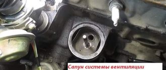
2. Release the clamp by attaching the additional hose to the breathing cap (marked with a red arrow) and disconnect the additional hose. Continue unscrewing the main hose clamp (marked with the blue arrow) and remove it from the cover.
3. Remove the engine oil level sensor.
4. Unscrew the bolt securing the fan cover and remove the cover from the car engine.
5. Dampen a cloth with kerosene and wipe the inside of the oil separator.
The note! Be careful when wiping; Do not allow dirt to get inside the engine. If you are not comfortable cleaning dirt from the installed oil separator, remove it from the vehicle by unscrewing the lock nut (indicated by the red arrow). Place the removed oil separator in a prepared container with kerosene.
6. Clean the surface of the air filter from dirt by wiping it with a cloth soaked in kerosene.
The note! Remove the gasket from the filter housing and clean it of dirt.
Installation
This is done in the reverse order of removal.
The note! Replace broken or cracked gaskets with new ones. Make sure the metal shims are inserted into the air filter housing gasket (shown in photo).
READ Alarm Installation Map for VAZ 21214
Important! If a large amount of kerosene gets into the crankcase, change the engine oil! (Read more in the article “Changing Engine Oil”)
For beginners! Question: What does the oil separator look like? Answer: in the photo.
Source
Welcome! The crankcase ventilation system is necessary to ensure that the atmosphere is not clogged and the exhaust gases are allowed to burn out again, this system has been implemented in many cars, from VAZ 2101 to cars such as Lada Priora, Lada Granta, etc., but when the engine is worn out, This system is removed by people themselves by removing all the PCV hoses, usually in a bottle or just outside, we will break it down in this article, so if your car has already been driven quite a lot, this article will be sent to you.
The note! We will look at cleaning the ventilation only on 16 valve engines, if you have 8 valves, then we will move on to the article: “Cleaning the crankcase ventilation on a VAZ 2114”, this engine is described in this article, you will need to clean the ventilation, crankcase 16 drain: pliers are not large , screwdrivers with different heads and all kinds of wrenches, in addition, you will need sealant for the cylinder head cover and a new gasket!
Troubleshooting
The first thing you need to pay attention to is the color of the exhaust, blue or black smoke, a sign of burnt valves or problems with rings. Next, you should check the compression in all cylinders. The value on gasoline internal combustion engines should be within 11-13 MPa. Disconnect the pipes from the valve covers, air intake and breather
Assess the degree of contamination. If the pipes are very dirty or clogged with oil deposits, use gasoline to clean them or a special carburetor cleaner. Check the condition of the oil separator. Unscrew the required bolts to get to this unit. Remove the oil separator and assess its condition. If necessary, clean or rinse followed by drying. Inspect and, if necessary, flush the breather valve. There are situations when the valve gets stuck, resulting in exhaust gases entering the crankcase and creating excess pressure. Remove the part and wash it; in most cases, this will resolve the issue of squeezing oil out of the breather.
Helpful advice! To distinguish stuck rings from a burnt-out valve, it is enough to perform several manipulations. After checking the compression in the cylinders, determine the cylinder with the lowest value. Then inspect the spark plug of this cylinder; if the rings are lodged in this cylinder, the spark plug will be covered with a thick oil layer. If the valve is burnt out, the spark plug will appear normal without any major abnormalities.
Finally…
The problem of oil escaping through the breather worries many motorists and causes a lot of trouble, but with timely detection of the problem and the right approach, serious consequences can be avoided
It is important to ensure that the oil level is normal, as soon as you find that the engine is taking oil, monitor its level and constantly monitor that it does not fall below the permissible level
Also pay attention to the breather and filter; oil on the air filter in large quantities also does not bode well. Regularly monitor the condition of the engine and all systems, and also promptly correct any malfunction
This will save you from engine overhauls and unnecessary waste.
Crankcase ventilation system
Crankcase ventilation system
: 1 - centrifugal oil separator; 2 - suction hose; 3 - flame arrester; 4 — exhaust ventilation manifold; 5 - suction pipe; 6 — gas exhaust pipe; 7 - spool; 8 — air filter; 9 — oil separator drain pipe; A - spool action when the throttle valve is closed; B - the action of the spool when the throttle valve opens.
When the engine is running, some of the gases (located in the combustion chamber under a pressure of over 40 kg/cm2) penetrate through the piston ring barrier into the crankcase. These gases contain harmful impurities that contribute to the formation of viscous substances in the lubricant and negatively affect the durability of parts. In addition, the increased pressure in the crankcase created by escaping gases causes oil to leak through the seal. To remove the so-called crankcase gases and supply clean air to the engine crankcase, a ventilation system is used. The system used on the Zhiguli is distinguished by unusual design features. The gases in the crankcase are sucked off due to the vacuum in the intake manifold through hose 2 connected to air filter 8. An inertial centrifugal oil separator 1 is installed at the inlet of this hose. The oil mist contained in the gases is thrown onto the walls of the separator, condenses and flows down the drain tube 9 into the oil pan. In the place where hose 2 enters the exhaust ventilation manifold 4, manufactured integrally with the air filter housing 8, a flame arrester 3 is installed. In the event of a backfire in the carburetor, it prevents the flame from spreading through hose 2 into the crankcase. Manifold 4 is connected (pipe 6) to the primary mixing chamber of the carburetor, as well as (pipe 5) to the internal cavity of the air filter. Due to the vacuum created in them during engine operation, gases from the crankcase are sucked into the intake pipe. From there they enter the cylinders and are partly burned along with the combustible mixture, and partly are ejected along with the exhaust gases. The gases discharged through tube 6 enter the carburetor through spool 7, which changes the flow area of the tube. This is necessary because the maximum vacuum in the mixing chamber is formed when the throttle valve is closed (position “A” in the figure). In this mode, the breakthrough of gases is small and a small flow area is sufficient to suck them out. When the throttle is opened, the vacuum in the mixing chamber decreases, but the spool mechanically connected to the throttle valve increases the flow area of the tube (position “B”). With further opening of the throttle, the vacuum in tube 6 continues to fall and becomes negligible. At the same time, the vacuum in the area of pipe 5 increases, through which the main air suction begins; The vacuum that occurs in the crankcase is compensated by fresh air supplied into it. For this purpose, a special hose is used (not visible in the figure) running from the air filter to the upper part of the chain casing, the cavity of which communicates with the crankcase. Thus, when the engine is running, circulation constantly occurs in its crankcase - crankcase gases give way to clean air.
Source
Five ways to defeat engine oil burns without major repairs
Typically, oil leaks are observed on cars that have run about 150 thousand km, but it happens that the engine begins to “sweat” on new cars due to defective or incorrectly installed sealing parts.
Accordingly, your task is to detect leak locations. Note that the most common crankshaft seals that lose their seal are the front and rear oil seals. There are also frequent cases when camshaft seals lose their tightness. Finally, the oil drain plug or oil filter may be leaking oil.
Most often, the problem is solved with little effort - replacing gaskets and seals. But if the engine is turbocharged, the turbocharger oil supply and drain pipes may leak. In this case, oil risks getting into the intake system and contaminating the piston part, as well as into the exhaust system, and then the catalytic converter will be at risk.
This solution is a half-measure, but in some cases, especially when the car is not new, and it is necessary to extend its life as much as possible without resorting to major repairs, it is quite effective. There is no point in radically increasing the viscosity.
For example, if you previously used 0W-20 or 5W-30 oils, then you can try a lubricant with a value of 5W-40. Almost immediately after changing the oil, you will feel a difference in the engine’s oil appetite.
However, the price for such a decision may be a deterioration in the starting performance of the engine, especially in severe frosts in winter. In addition, switching from synthetic oil to semi-synthetic and even mineral water can solve the problem. You just need to make sure that such lubricants meet the car manufacturer’s tolerances.
A fairly common case is when valve stem seals, also known as valve seals, wear out over time and begin to leak oil. The causes of wear may be temperature changes (for example, after the engine overheats), or engine oil that is incompatible with rubber structural elements.
It all depends on the design of your motor. In some cases, these parts can be replaced without removing the cylinder head, so you definitely won’t go broke on such repairs. However, it is often necessary to remove the camshafts, which involves disassembling the front of the engine; usually the cylinder heads also need to be removed. However, the costs of such events are still not comparable in price to major repairs. Oil consumption from such a procedure can be reduced several times.
SVKG device in Lada Priora
In all brands of cars, the SVKG is built on a similar principle. Only small details differ. On the upper side of the crankcase there is an oil separator, which looks like a hollow plug. An oil deflector is placed under the plug, which is designed to clean the gases from the crankcase as much as possible from oil particles. The oil separator has an outlet for the crankcase ventilation hose.
In order for the gases to return to the cylinder chamber, a ventilation valve is placed along their path. The valve has three modes, which allows you to maintain a certain level of gas rarefaction in the crankcase.
While the engine is idling, gases move through a small circuit hose through a special passage hole in the throttle assembly. At this time, a high vacuum is created in the intake hose, which allows crankcase gases to be effectively sucked out of the throttle block. The passage hole in the throttle regulates the amount of gases that are sucked out.
This allows you to stabilize the engine in idle mode. When the car begins to move, the throttle valve opens, causing gases from the crankcase to enter the cylinder through a large circuit hose for combustion.
Article: 2112-1014056, additional articles: 2112-1014056Р
Order code: 006580
- Buy with this product
- show more
Passenger cars / VAZ / VAZ-21101 drawing
» href=»/catalog/vaz-3/legkovye_avtomobili-30/vaz_2110-10/sistema_smazki_i_ventilyacii-105/#part40486″>Lower hoseEngine / Lubrication and ventilation system
- Passenger cars / VAZ / VAZ-21121 drawing
- » href=»/catalog/vaz-3/legkovye_avtomobili-30/vaz_2112-12/sistema_smazki_i_ventilyacii-105/#part49102″>Lower hoseEngine / Lubrication and ventilation system
- Passenger cars / VAZ / Lada Priora 21701 drawing
- » href=»/catalog/vaz-3/legkovye_avtomobili-30/lada_priora_2170-480/sistema_smazki_i_ventilyacii-77/#part1578912″>Lower hoseEngine / Lubrication and ventilation system
- Passenger cars / VAZ / Lada Kalina 2192, 21941 drawing
- » href=»/catalog/vaz-3/legkovye_avtomobili-30/lada_kalina_2192__2194-1646/sistema_smazki_i_ventilyacii-56/#part3652972″>Lower hoseLubricating system / Lubrication and ventilation system
- Passenger cars / VAZ / Lada Kalina 21941 drawing
- » href=»/catalog/vaz-3/legkovye_avtomobili-30/lada_kalina_2194-1886/a501__sistema_smazki_i_ventilyacii-130/#part4210486″>Lower hose Lubrication system / A501. Lubrication and ventilation system
- Passenger cars / VAZ / Lada Granta 21901 drawing
- » href=»/catalog/vaz-3/legkovye_avtomobili-30/lada_granta_2190-1893/a501__sistema_smazki_i_ventilyacii-122/#part4242903″>Lower hoseLubricating system / A501. Lubrication and ventilation system
- Passenger cars / VAZ / VAZ-21111 drawing
- » href=»/catalog/vaz-3/legkovye_avtomobili-30/vaz_2111-11/sistema_smazki_i_ventilyacii-105/#part44794″>Lower hoseEngine / Lubrication and ventilation system
- Passenger cars / VAZ / VAZ-2110, 2111, 21121 drawing
- » href=»/catalog/vaz-3/legkovye_avtomobili-30/vaz_2110__2111__2112-415/sistema_smazki_i_ventilyacii-120/#part1302912″>Lower hoseEngine / Lubrication and ventilation system
- Passenger cars / VAZ / Lada Kalina 1119 Sport1 drawing
- » href=»/catalog/vaz-3/legkovye_avtomobili-30/lada_kalina_1119_sport-1556/sistema_smazki_i_ventilyacii-33/#part3438987″>Lower hoseLubricating system / Lubrication and ventilation system
- Passenger cars / VAZ / Lada Priora 21728 Coupe1 drawing
- » href=»/catalog/vaz-3/legkovye_avtomobili-30/lada_priora_21728_coupe-1878/sistema_smazki_i_ventilyacii-80/#part4190138″>Hose lower Lubrication system / Lubrication and ventilation system
- Passenger cars / VAZ / Lada Priora 2170 FL1 drawing
- » href=»/catalog/vaz-3/legkovye_avtomobili-30/lada_priora_2170__fl-1889/a501__sistema_smazki_i_ventilyacii-146/#part4224085″>Lower hoseLubricating system / A501. Lubrication and ventilation system
- Passenger cars / VAZ / Lada Vesta1 drawing
- » href=»/catalog/vaz-3/legkovye_avtomobili-30/lada_vesta-1883/141010__separator-148/#part4202781″>Crankcase VENTILATION HOSEAdsorber, separator / 141010. Separator
There are no reviews for this product yet.
Today, in the next article in the series “Crystal VAZs or typical breakdowns of domestic cars,” we will talk about the latest developments of the Volzhsky Automobile Plant: Lada Grante and Lada Largus. Let's talk about the history of the creation of these models, as well as their characteristic malfunctions.
Engine crankcase ventilation
Crankcase ventilation is designed to remove crankcase gases resulting from the breakthrough of fuel combustion products through the gaps between the liner and piston rings and their interaction with oil vapor.
The gases contain sulfur compounds and water vapor that pollute the oil, which form sulfuric and sulfurous acids, which significantly deteriorate the quality of the oil. Water vapor causes the oil to foam and form an emulsion, which makes it difficult for oil to reach the rubbing surfaces. Gases escaping into the crankcase increase its pressure, which can cause oil leakage through the crankcase seals.
It is also unacceptable for gases to penetrate under the engine hood, and then into the body and cabin of the car, since the harmful substances contained in the gases are dangerous for passengers and the driver. Suction of crankcase gases reduces oil aging, and also, by creating a vacuum in the pan, prevents the possibility of oil leakage through the seals.
There are two types of crankcase ventilation used in automobile engines:
- open – with crankcase gases vented into the environment;
- closed - with gases being sucked into the engine intake system.
Open ventilation (Fig. 1) is carried out under the influence of vacuum that occurs in the exhaust pipe due to the relative movement of air when the car is moving. To prevent oil particles from being carried away along with crankcase gases, a special labyrinth-type breather is used, on the walls of which oil drops settle and flow into the pan.
The disadvantage of an open crankcase ventilation system is its low efficiency, as well as the poisoning of the environment with substances harmful to human health and wildlife.
In closed systems, gases may be vented into the air cleaner before the carburetor or directly into the intake manifold. Gas removal through the air cleaner does not create the required suction intensity at minimum crankshaft speeds and full load. In addition, the passage of crankcase gases through the carburetor causes tarring of its channels, jets and moving parts. Therefore, a system with gas suction directly into the engine intake manifold, in which there is always a vacuum, is more preferable.
The ventilation system shown in Fig. 2, works as follows: under the influence of vacuum in the intake pipe 10, crankcase gases rise upward and through the elbow 9 and hose 5 enter the oil separator housing, closed by a lid 1. Between the lid and the housing there is a rubber membrane 2, pressed by a spring 3 to the housing. Oil particles settling at the bottom of the oil separator housing are drained through tube 6 into the engine crankcase.
Using membrane 2, which is located on one side under atmospheric air pressure, and on the other under the pressure of crankcase gases and springs, excess pressure is maintained in the crankcase.
In Fig. Figure 3 shows a diagram of the crankcase ventilation of a carburetor engine of VAZ cars. Here, crankcase gases are sucked through the oil separator 7 and hose 6 into the exhaust manifold 4 of air filter 3. From the exhaust manifold at idle and at low engine loads (when the vacuum in the air filter is low), crankcase gases flow through hose 2 and spool 1 under the carburetor throttle valves .
In other engine operating modes, crankcase gases enter the carburetor through air filter 3. Oil is released in oil separator 7 and flows through outlet tube 8 into the oil pan. Flame arrestor 5 prevents flame from penetrating into the engine crankcase during possible flare-ups in the carburetor.
Source
How often should cleaning be performed?
If the ventilation system is clogged and its filter is unable to clean the mixture passing through it, then not only unburned gases, but also oil particles and other pollutants will enter the engine. All this will ultimately have a negative impact on both the operation of the engine and its remaining service life.
The frequency with which the crankcase ventilation of the VAZ 2114 should be cleaned directly depends on the condition of the engine. So, if the car just recently came off the assembly line, and its engine has not clocked up 50,000 km, you shouldn’t even think about cleaning it, since the piston rings are still new, and there is practically no leakage of gases through them.
Valve cover of VAZ 2114 engine
The first cleaning (as recommended by AvtoVAZ itself) should be performed after the car has covered 60,000 km. And all subsequent cleanings should also be performed after every 60,000 km.
PRIORA oil in the air duct
Hello everyone. In general, the client’s car had covered 70,000 thousand miles, with five thousand kilometers, oil appeared in the air duct, ran out from under the valve covers - in general, the engine was all in oil, this did not bother him much - while the oil began to accumulate strongly in the air duct, then it ran through the DMV to air filter. In general, the oil level was enough for 6,000 thousand. I changed the valve seals, piston rings, timing belt, etc. I left. The other day he arrived (5,000 thousand traveled) oil in the air line, pressure is normal, gases do not go into the breather, in principle says it doesn’t consume oil (strains the oil in the air duct) maybe with a separator (on the valve cover) what’s wrong (no wonder oil appeared in the air duct in the first 5 thousand) anyone have any thoughts? The car was taken from the showroom
Operating principle of SVKG
Car engines have a ring gas exhaust system. The resulting gases as a result of the combustion of diesel fuel, gasoline or liquefied gas are not released into the environment, but are returned to the engine, where they are re-burned. The second end of the crankcase ventilation hose is attached to the intake manifold, with the help of which gases again enter the cylinder chamber for combustion. A significant part of the gases, when re-entered, ignite at the moment the fuel ignites, and the remaining ones are released into the atmosphere using the exhaust system. A small percentage of the gases are sent back into the cylinder chamber for re-combustion. This process is ongoing.
