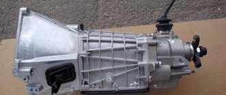
When designing the VAZ-2105, the designers slightly redesigned the gearbox, changing the gear ratios of each gear. But in general, the design of the gearbox of this car was not very different from previous modifications.
The first gearboxes were four-speed, three-shaft, with constant mesh gears and synchronizers in all forward gears. Later this box was modified by adding an additional 5th speed. Moreover, the 4-speed modification was taken as the basis for its creation, so the five-speed direct transmission remained in 4th speed.
Subsequently, the gearbox developed for the VAZ-2105 became the main one and was equipped with all cars of the classic family until their production ended. In the future, we will consider the maintenance of a 5-speed gearbox, since the repair of a 4-speed VAZ-2105 gearbox is done basically in the same way as a five-speed gearbox, due to the fact that the design of these versions of the gearbox is largely similar, then maintenance and repair operations - identical. We will also find out how to convert a 4-speed modification into a five-speed one.
The main advantage of such a gearbox was the high reliability of the unit and unpretentiousness in operation, so repair of the VAZ-2105 gearbox is not required very often; it is capable of working out a significant service life without any special intervention and with minimal maintenance. Another positive quality is the maintainability and availability of spare parts and repair kits, so repair of the 2105 gearbox can be performed even in a garage with a basic set of tools.
Gearbox service
But first you should consider the maintenance that needs to be carried out on this unit. There is only one thing - checking the level of lubricant and, if necessary, topping it up to the required level.
A manual transmission itself is not demanding, so the lubricant used in it performs only one function - it lubricates the component parts of the unit. Therefore, the oil in the box should be changed every 60 thousand kilometers.
Before servicing the gearbox, you should know what kind of oil to pour into the VAZ-2105 gearbox. The transmission of this car requires gear oil with an API quality level of GL-5 or higher and a viscosity of 75W-90 or 85W-90 according to the SAE classification. The oil volume in the gearbox is 1.35 liters.
Checking the oil in the box is not difficult, but to do this, the car should be placed on an inspection hole or overpass.
And then the actions are as follows:
- On the left side of the gearbox housing (in the direction of travel of the car) we find the control filler plug (located just above the bottom cover of the box);
- Use a rag to remove dirt around the plug;
- Using a wrench of the required size, unscrew the plug;
- You can find out the level using a small mirror and a flashlight, a screwdriver or even your finger, in general, whatever is convenient. The lubricant level is considered normal if the oil reaches the bottom edge of the hole;
- If the oil level is below the level, use a technical syringe to bring it up to normal (as soon as the oil begins to flow out of the hole, tighten the plug);
Checking and adding lubricant to the gearbox should be “cold”. If maintenance is carried out immediately after a trip, it is necessary to allow time (10-15 minutes) for the oil to completely drain, otherwise the level will be incorrect when checking.
If the time has come to change the oil, then first drain the used lubricant - clean the bottom cover of dirt, place a plastic container and unscrew the drain plug.
Then wait until the oil has completely drained and tighten the plug.
And then everything is done in the same way as when checking and replenishing the level, only you will have to pump the required amount of oil into the box with a syringe.
After replacement, you should not immediately dispose of the waste; before doing so, it is better to check it. To do this, take a magnet, tie a thread and lower it into a container with old oil. Next, you should move the magnet along the bottom. Then we take it out and examine it. If a large amount of metal shavings is found on the magnet, this may indicate the appearance of intense wear, and in this case, overhauling the gearbox and troubleshooting the components will not be superfluous, since it will allow identifying and eliminating the malfunction at an early stage.
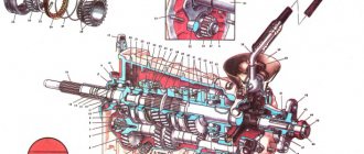
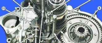
The device of a five-speed gearbox in the VAZ-2107.
A car's manual gearbox is a rather complex device. In general, it consists of three main parts - shafts. Each of them has its own purpose:
- — the primary (drive) shaft on which the drive gears and synchronizers that equalize their speed are mounted;
- — intermediate shaft
- - secondary (driven) shaft, also equipped with gears.
These mechanisms and components are protected by a common housing on three sides, and the handle of the gear control lever is located on top.
To understand the principle of operation of a five-speed gearbox, you should consider its structure in detail.
Primary shaft
- design equipped with gears. It is mounted on a bearing located in the cavity of the gearbox housing.
Manual transmission secondary shaft
continues the drive shaft. The gears of the first three gears are fixed there. They are all different diameters, and it is due to this that the difference in gear ratios is achieved.
Table: five-speed gearbox gear ratios
| broadcast | meaning |
| first | 3,67 |
| second | 2,10 |
| third | 2,0 |
| fourth | 1,0 |
| fifth | 0,82 |
The rotation of the secondary shaft is carried out not by one, but by three bearings, one of which is installed directly in the drive shaft, and the remaining two are inside the crankcase and directly in the rear housing cover.
Intermediate shaft
also rotates on three ball bearings, and the gears form a single whole with it. This unit transmits a moment of force of a given value from the drive shaft to the driven one.
The reverse gear is mounted on a separate small shaft connected to the driven transmission shaft through several splines.
The driver shifts gears using so-called forks, driven by a lever located inside the cabin, to the right of the driver. When the position of the lever changes, its hinge engages with a recess of a certain rod, which is secured with the other side to the fork. The fork itself is located in the groove of the corresponding gear. When the shift lever moves, the fork also moves, whereby the desired gear on the driven shaft meshes with a specific intermediate gear. Consequently, the rotation of the driven shaft of the box acquires the speed that corresponds to the gear ratio of the connected gears.
When shifting into reverse, the fork comes into contact with the reverse idler gear. To turn it on, you need to push the gearshift lever down.
The filler hole for transmission oil in the box of the VAZ-2107 car is located on the left in the body and is closed with a sealed plug. To avoid oil leakage from the manual transmission pan, all bearings are protected by seals.
A mechanical five-speed three-shaft gearbox is a complex mechanism, so disassembling and repairing it should not be done with your own hands or at home.
The design of the VAZ 2107 car involves equipping it with a five-speed gearbox, the schematic diagram of which is presented below.
Gearbox device "VAZ 2107"
AvtoVAZ designers used a four-speed transmission used on earlier models of the Lada family as the basis for creating the “Seven” transmission. The differences in the new gearbox are not significant and are expressed in a change in the appearance and geometric shape of the rear cover caused by the addition (at the end of the driven shaft) of fifth-stage elements.
The increase in the number of gears provided the following positive aspects during the operation of the car:
- Expanding the speed range made it possible to operate the vehicle in the most economical modes.
The operational period of the power unit has been increased.
The introduction of an additional gear did not change the size of the gear ratios in comparison with the basic version and the number of shafts (three), which makes most of the parts of the new and old gearbox interchangeable.
The VAZ 2107 gearbox consists of several main structural elements:
- The input shaft of the VAZ 2107 gearbox is absolutely identical to the shaft used in the transmission of a four-speed gearbox.
An intermediate shaft with a threaded hole for fastening the rear and fifth gears, located at the rear end.
The secondary shaft of the VAZ 2107 gearbox, which differs from the “predecessor” in the fifth-stage elements placed on it.
Aluminum crankcase with stamped steel cover.
The gearbox is lubricated using transmission oil poured into the crankcase (1.35 liters). To seal the ends of the primary and secondary shafts, special oil seals (cuffs) are used.
Common faults
Now let's go over the main malfunctions that can occur with the gearbox. There are not many of them, but most of them are eliminated using the transmission removed from the car.
So, the main malfunctions of the VAZ-2105 gearbox are:
- Increased noise when the gearbox is operating (at a certain speed or at all);
- Difficulty switching to another speed;
- Unclear switching, speed loss;
- Lubricant leaks;
In turn, each malfunction can have several causes.
Noise Removal
The noise of the VAZ-2105 gearbox can occur due to wear of bearings, wear of gear teeth and gears, as well as synchronizers, and axial displacement of the shafts relative to each other.
If such a problem occurs, it will be necessary to remove the transmission from the car, since it cannot be repaired otherwise. Note that eliminating noise is one of the most difficult operations to perform, since it requires complete disassembly and reassembly of the gearbox with replacement of worn elements.
In addition to the standard set of keys and screwdrivers, you will additionally need a universal puller. Next, we’ll look at how to completely disassemble a VAZ-2105 5-speed gearbox.
So, all work is done on the removed gearbox:
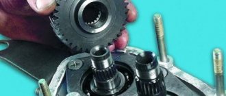
- Drain the oil and remove the bottom cover. We immediately assess the condition of the gear teeth. If their damage is not noticeable, most likely the noise is coming from the bearings;
- We check the position of the gearshift lever (it should be in neutral), after which we dismantle the gear shift mechanism (link) from the gearbox;
- Remove the cover of the clamps and remove the springs and balls;
- We remove the elastic coupling from the secondary shaft, and then its hub (to unscrew the hub nut, unscrew the bolt securing the 3rd and 4th gear forks, engage 1st gear in the gearbox and displace the 4th gear synchronizer clutch. Two at a time the gears are engaged, the gearbox will be blocked and the nut can be unscrewed);
- We unscrew the speedometer drive, the sensor for turning on the reverse speed light and the exhaust system pipe mounting bracket;
- We unscrew the fastening elements of the rear gearbox cover (5-speed gearboxes have 5 external nuts and 1 internal nut, 4-speed gearboxes do not have an internal nut). Then remove the cover. In this case, the bearings are second. the shaft and the 5th gear block will be disassembled - the inner races will remain on the shafts, and the outer ones, together with the rolling elements, will be in the cover, and all this will need to be dismantled for replacement;
- Remove the speedometer drive gear and oil deflector from the secondary shaft;
- We dismantle the gear block of the 5th and reverse gears by unscrewing its fastening bolt installed in the shaft, as well as the reverse intermediate gear from the axle;
- Remove the 5th gear synchronizer from 2nd. shaft, the 5th and reverse gear shift fork together with the axle, then remove the 3rd and 4th gear axle block;
- We dismantle the synchronizer hub and the reverse gear from the second. shaft;
- We unscrew the bolts securing the pressure plate of the secondary shaft bearing and remove it;
- Unscrew the clutch housing from the gearbox;
- Unscrew the intermediate shaft bolt and remove the front bearing;
- We remove the rear bearing of the intermediate shaft, after which it can be pulled out of the box body;
- We remove the axles and forks of the remaining gears, as well as the axle block of the 1st and 2nd gears;
- We take out the input shaft;
- We remove the secondary shaft along with the gears;
Well, then troubleshooting of the component elements is carried out, worn and damaged components are replaced and assembly is carried out.
Note that this disassembly diagram is general and does not consider such nuances as removing retaining rings, sealing washers, engravers and other small elements.
Disassembly and assembly of the VAZ 2105 Zhiguli gearbox
- Repair manuals
- Repair manual for VAZ 2105 (Zhiguli) 1980-1992.
- Disassembly and assembly of the gearbox
Removing the elastic coupling flange using a puller A.40005/3/9B/9С
| 1 – elastic coupling flange; 2 – bolts for fastening the device to the flange; 3 – strip 9C of puller A.40005/3; 4 – puller A.40005/3 |
Internal view of the clutch housing
| The red arrows indicate the nuts securing the clutch housing to the gearbox. The white arrow indicates the hole in the front cover for releasing oil from the gearbox housing to prevent oiling of the clutch discs. |
Internal view of the rear gearbox cover
| 1 – screw with an eye for fastening the tension spring of the gear shift lever; 2 – lever release spring; 3 – gear shift lever; 4 – screw for limiting the lateral travel of the lever. The arrow indicates the direction in which you need to move the lever to disengage it from the heads of the gear shift rods and remove the rear transmission cover. |
Main shaft parts
| 1 – retaining ring; 2 – spring washer; 3 – bearing; 4 – input shaft; | 5 – synchronizer spring; 6 – synchronizer blocking ring; 7 – retaining ring; 8 – bearing |
Secondary shaft parts
| 1 – retaining ring; 2 – spring washer; 3 – synchronizer hub; 4 – synchronizer clutch; 5 – retaining ring; 6 – synchronizer blocking ring; 7 – synchronizer spring; 8 – washer; 9 – third gear gear; 10 – secondary shaft; 11 – 2nd gear gear; 12 – washer; 13 – synchronizer spring; 14 – blocking ring; 15 – retaining ring; 16 – synchronizer hub; 17 – synchronizer clutch; 18 – retaining ring; | 19 – synchronizer blocking ring; 20 – synchronizer spring; 21 – washer; 22 – 1st gear gear; 23 – bushing of the 1st gear gear; 24 – bearing; 25 – reverse gear; 26 – spring washer; 27 – retaining ring; 28 – speedometer drive gear; 29 – rear bearing; 30 – oil seal; 31 – elastic coupling flange; 32 – nut; 33 – seal; 34 – centering ring; 35 – retaining ring |
Shift Lever Parts
| 1 – tension spring bolt; 2 – washer; 3 – tension spring; 4 – gasket; 5 – guide cup; 6 – gasket; 7 – washer; 8 – limit bolt; 9 – gear shift lever; 10 – ball joint; 11 – spherical washer; 12 – spring; 13 – support washer; 14 – retaining ring; | 15 – gasket; 16 – flange; 17 – spring washer; 18 – nut; 19 – cuff; 20 – inner cover; 21 – lever rod; 22 – cap; 23 – thrust pad; 24 – elastic bushing; 25 – spacer sleeve; 26 – elastic bushing; 27 – locking sleeve |
Disassembly
| EXECUTION ORDER | ||
Assembly
|
Difficulty switching
Now let's briefly look at other faults. Difficulty shifting gears will be next.
The reason for this may be:
- Wear of the switching mechanism or its deformation (scenes);
- Wear, the appearance of burrs on the gear shift axles or on their seats, jamming of the crackers;
- Damage or wear of the splines of the synchronizer sliding couplings;
- Damage and bent shift forks;
In the first case, to restore functionality, you don’t even need to remove the transmission from the car, since replacing the VAZ-2105 gearbox shifter is possible without dismantling the transmission unit.
To do this, it is enough to remove the lever, boot, and plastic protective cover to provide access to the fastening elements of the switching mechanism, which must be unscrewed in order to remove the mechanism assembly. And then it is replaced or repaired.
Important! In a 4-speed gearbox, a tension spring is attached to the rod from inside the crankcase, which ensures a constant position of the lever opposite 3-4 gears and prevents its vibration. Therefore, when removing the mechanism, you should first lift it a little, and then pry the spring with a hook made of steel wire, remove it from the eye of the rod and hold it in a slightly tense position so that it does not fall into the crankcase. Before installing the new link, use the same hook to hook the spring and install everything in place.
As for other breakdowns that make it difficult to engage the gears, you will have to remove the gearbox, disassemble it, identify the worn or damaged element and replace it.
Place the car over an inspection ditch (or on a lift), put stops under the front wheels and hang the rear axle on one or both sides. Release the parking brake and set the gear shift lever to neutral. Disconnect the wires from the battery. Remove the front floor mat and the outer cover of the gear shift lever, the plastic cover and the seal. Pressing down the rod 22 (see Fig. 1) of the lever, using a screwdriver or some other pointed tool, remove the locking sleeve 26 from the groove of the lever and remove the rod.
Disconnect the muffler pipe suspension at the rear of the car, and then the muffler pipe from the exhaust pipe. Disconnect the clamp securing the exhaust pipe to the gearbox. Using wrench 02.7812.9500, unscrew the nuts securing the exhaust pipe of the mufflers to the exhaust manifold and remove the pipe. Unscrew the lower bolts securing the clutch housing cover and disconnect the ground wire from the clutch housing and the wires from the reverse light switch.
Rice. 2. Clutch release drive: 1 — fork release spring; 2 - lock nut; 3 — adjusting rod nut; 4 - cotter pin; 5 — clutch release fork; 6 — pusher; 7 — bolt securing the working cylinder to the clutch housing; 8 - clutch release working cylinder
Unhook the release spring 1 from the clutch release fork 5 (Fig. 2) and remove the cotter pin 4 from the pusher 6. Disconnect the slave cylinder 8 from the clutch housing. In this case, cylinder 8, connected to the pipeline going to the main cylinder of the clutch release drive, remains on the car, which eliminates the loss of brake fluid and the need for subsequent pumping of the hydraulic clutch release drive.
Rice. 3. Elastic coupling connecting the propeller shaft to the gearbox: 1 - bolts securing the driveshaft flange to the elastic coupling; 2 — nuts of bolts securing the flange of the secondary shaft of the gearbox to the elastic coupling; 3 - device A.70025; 4 - elastic coupling; 5 — cross member of the rear engine mount
Remove the driveshaft safety bracket. Disconnect the speedometer flexible shaft from the speedometer drive gearbox.
Place clamp A.70025 on elastic coupling 4 (Fig. 3) and tighten it. This will facilitate the removal and subsequent installation of the flexible coupling. Unscrew the nuts 2 and, turning the propeller shaft, remove the bolts securing the elastic coupling 4 to the flange of the secondary shaft of the gearbox. Lower and move the front driveshaft and coupling to the side.
Using a hinged socket wrench 02.7812.9500, unscrew the bolts securing the starter to the clutch housing and release it.
Remove the clutch housing cover bolts.
Disconnect the rear engine mount from the cross member, and then remove the cross member while supporting the transmission from below.
Place a jack, trestles or other suitable support under the gearbox housing. Using a hinged socket wrench A.55035, unscrew the mounting bolts and remove the gearbox along with the clutch housing, moving it to the rear of the car so as to remove the gearbox input shaft from the front bearing and from the clutch driven disc hub.
WARNING
When removing or installing the gearbox, it is strictly forbidden to rest the end of the input shaft on the thrust flange of the clutch pressure spring, so as not to deform the clutch connecting plates.
Disassembly and assembly of the gearbox
Disassembly.
Wash the gearbox and install it on a stand. Drain the oil and remove the bottom cover with gasket.
Remove the clutch release fork, and from the guide sleeve of the front gearbox cover, remove the clutch assembly with bearing and connecting spring.
Remove the clutch housing with the gasket and the front cover of the gearbox (along with the oil seal and spring washer) (Fig. 4).
Rice. 4. Internal view of the clutch housing.
The black arrows indicate the nuts securing the clutch housing to the gearbox; The white arrow indicates the hole in the front cover for releasing oil from the gearbox housing to prevent oiling of the clutch discs
Remove the speedometer drive with the gasket and the reverse light switch, being careful not to deform its housing.
Remove the bolt securing the 3rd and 4th gear shift fork. Install clamp 41.7816.4068 on the input shaft or engage two gears at the same time. This will prevent the primary, secondary and intermediate shafts from turning and will allow subsequent disassembly operations to be performed.
Rice. 5. Removing the retaining ring
Remove the retaining ring from the end of the transmission output shaft (Fig. 5).
Rice. 6. Removing the centering ring of the elastic coupling of the cardan shaft using ejector A.40006/1 and puller A.40005/4
Having straightened the lock washer, unscrew the nut a few turns to move the centering ring of the elastic coupling, and tighten the nut again. Using a pusher A.40006/1 with a puller A.40005/4, remove the centering ring of the elastic coupling of the propeller shaft from the end of the secondary shaft (Fig. 6).
Rice. 7. Removing the elastic coupling flange using a puller A.40005/3/9B/9C: 1 - elastic coupling flange; 2 — bolts securing the device to the flange; 3 — strip 9C of puller A.40005/3; 4 — puller A.40005/3
Remove the elastic coupling centering ring seal from the end of the secondary shaft, unscrew the nut and remove the elastic coupling flange using a puller A.40005/3/9B/9C (Fig. 7).
Rice. 8. Internal view of the rear cover of the gearbox: 1 - a screw with an eye for fastening the release spring of the gear shift lever; 2 — lever release spring; 3 — gear shift lever; 4 — screw for limiting the lateral travel of the lever. The arrow indicates the direction in which you need to move the lever to disengage it from the heads of the gear shift rods and remove the rear transmission cover
Remove the rear cover of the gearbox by unscrewing the nuts securing it and screw 4 (Fig. limiting the lateral travel of the lever and moving the gear shift lever to the left to free it from the gear shift rods.
Rice. 9. Removing the circlip of the countershaft reverse gear
Remove the rear bearing from the output shaft. Remove the speedometer drive gear.
Remove the fork with the spacer bushing from the reverse rod. Remove the reverse idler gear from the axle.
Remove the reverse drive gear retaining ring from the intermediate shaft (Fig. 9); Remove the gear and spring washer.
Rice. 10. Removing the intermediate shaft from the gearbox housing
Remove the reverse driven gear retaining ring from the secondary shaft by pressing the spring washer with mandrel 41.7816.4069 to relieve the load on the retaining ring. Remove the reverse driven gear and spring washer.
Using shaped mandrels (such as screwdrivers) and rod drifts, remove the front and rear intermediate shaft bearings from the gearbox housing. Make marks on the inner rings of the double-row front bearing, using which to install these rings in their original places in the outer ring of the bearing.
Remove the intermediate shaft from the gearbox housing by tilting it as shown in Fig. 10.
Rice. 11. Gear shift drive: 1 — reverse fork; 2 — tension spring of the gear shift lever; 3 — guide cup of the lever; 4 — ball joint of the lever; 5 — gear shift lever; 6 — spherical washer; 7 — lever spring; 8 — retaining ring; 9 — damper locking sleeve; 10 — elastic damper bushings; 11 — damper spacer bushing; 12 — damper thrust pad; 13 — gear shift lever rod; 14 — shift fork for III and IV gears; 15 — shift fork for 1st and 2nd gears; 16 — fork rod for 1st and 2nd gears; 17 — fork rod for 3rd and 4th gears; 18 — reverse fork rod; 19 — blocking crackers; 20 — clamp cover; 21 - bushing; 22 — clamp spring; 23 — retainer ball; 24 — rear cover of the gearbox; 25 — reverse light switch; 26 — remote bushing for reverse fork
Remove the cover 20 (Fig. 11) of the rod clamps together with the gasket, remove the springs and balls of the clamps. Remove rod 18 of the reverse shift fork and rod 17 of the shift fork for 3rd and 4th gears from the gearbox housing. Unscrew the bolt securing the forks of 1st and 2nd gears, remove the rod and forks. When removing the rods, simultaneously remove the three locking pins.
Rice. 12. Unscrewing the screws securing the locking plate of the intermediate bearing of the secondary shaft with a drill-screwdriver. The arrow shows the direction of the impact stroke of the screwdriver cage; use a hammer
Remove the locking plate (Fig. 12) of the secondary shaft intermediate bearing and the reverse idler gear shaft.
Rice. 13. Removing the input shaft from the gearbox housing
Using mandrels (like screwdrivers), remove the input shaft along with the bearing and synchronizer ring (Fig. 13) and remove the needle bearing from the front end of the secondary shaft.
Rice. 14. Removing the secondary shaft from the gearbox housing
Knock the secondary shaft out of the intermediate bearing, remove the intermediate bearing and tilt it as shown in Fig. 14, remove the secondary shaft assembly with gears, couplings and synchronizer rings from the crankcase. Remove the synchronizer clutch for 3rd and 4th gears from the shaft.
Rice. 15. Parts of the input shaft: 1 - retaining ring; 2 - spring washer; 3 - bearing; 4 - input shaft; 5 — synchronizer spring; 6 — synchronizer blocking ring; 7 - retaining ring; 8 - bearing
Disassemble the input shaft (Fig. 15):
— remove the locking ring 7, the blocking ring 6 and the synchronizer spring 5;
— install the shaft on the press and, using a mandrel 41.7816.4069, compress the spring washer 2, remove the locking ring 1, and then the spring washer and bearing 3.
Rice. 16. Secondary shaft parts: 1 - retaining ring; 2 - spring washer; 3 — synchronizer hub; 4 — synchronizer clutch; 5 - retaining ring; 6 — synchronizer blocking ring; 7 — synchronizer spring; 8 — washer; 9 — gear III gear; 10 - secondary shaft; 11 - 2nd gear gear; 12 — washer; 13 — synchronizer spring; 14 — blocking ring; 15 — retaining ring; 16 — synchronizer hub; 17 — synchronizer clutch; 18 — retaining ring; 19 — synchronizer blocking ring; 20 — synchronizer spring; 21 — washer; 22 — 1st gear gear; 23 — bushing of the 1st gear gear; 24 — bearing; 25 — reverse gears; 26 — spring washer; 27 — retaining ring; 28 — speedometer drive gear; 29 — rear bearing; 30 — oil seal; 31 — elastic coupling flange; 32 - nut; 33 - seal; 34 - centering ring; 35 — retaining ring
Disassemble the secondary shaft (Fig. 16):
— remove from the rear side of the shaft gear 22 of the 1st gear with sleeve 23, hub 16 with a sliding clutch for switching 1st and 2nd gears, gear 112 of the 2nd gear together with the synchronizer blocking ring 14;
— install the secondary shaft with mandrel 41.7816.4069 on the press (see Fig. 17), place support half rings 3 under the third gear gear and, pressing the mandrel on the spring washer, remove the retaining ring 2; then spring washer 4, the hub of the sliding clutch for shifting the 3rd and 4th gears and the 3rd gear gear.
Rice. 17. Installation of a retaining ring on the secondary shaft: 1 - mandrel 41.7816.4069; 2 - retaining ring; 3 - support half-ring; 4 - spring washer; 5 — press rod
Rice. 18. Parts of the gear shift lever: 1 — tension spring bolt; 2 — washer; 3 — tension spring; 4 - gasket; 5 — guide cup; 6 - gasket; 7 — washer; 8 — limit bolt; 9 — gear shift lever; 10 — ball joint; 11 - spherical washer; 12 - spring; 13 — support washer; 14 — retaining ring; 15 — gasket; 16 - flange; 17 — spring washer; 18 - nut; 19 — cuff; 20 — inner cover; 21 — lever rod; 22 — cap; 23 - thrust pad; 24 - elastic bushing; 25 — spacer sleeve; 26 - elastic bushing; 27 - locking sleeve
Disassemble the gear shift lever and rear cover:
— remove lever 20 (Fig. 18) of the lever, retaining ring 14, washer 13, spring 12 and spherical washer 11;
— disconnect the tension spring 3 of the lever from the eye of bolt 1;
— remove the cuff 19, unscrew the nuts securing the flange 16 and remove the lever together with the flange, support 10 and cup 5.
The gearbox is assembled in the reverse order of disassembly. Please note that:
— spring 22 (Fig. 11) of the reverse fork rod clamp ball is different from others
elasticity, it is painted green or has a cadmium coating;
— when installing the clutch housing with the front cover of the gearbox, the hole in the front cover should be located as shown in Fig. 4;
— before installation, coat the working surface of the oil seal with LITOL-24 lubricant;
— when assembling the secondary and intermediate shafts, use mandrels 41.7853.4028, 41.7853.4032, 41.7853.4039;
Rice. 19. Installation of the reverse gear lock ring on the secondary shaft: 1 - lock ring; 2 — mandrel 41.7816.4069; 3 - spring washer; 4 - secondary shaft reverse gear
— when installing the reverse gear retaining ring, use mandrel 41.7816.4069, as shown in Fig. 19.
CHECKING THE TECHNICAL CONDITION OF GEARBOX PARTS
Cleaning
Clean the transmission parts thoroughly before inspecting them. Use a brush or scraper to remove all deposits and clean the holes and slots from possible contamination; then rinse to remove and dissolve any remaining oil.
Blow off the parts with a stream of compressed air and wipe them gently. Blow out the bearings especially carefully, directing the stream of compressed air so that the rings do not rotate rapidly.
Crankcase and covers
There should be no cracks on the crankcase, and there should be no wear or damage on the surface of the bearing bores.
There should be no damage to the mating surfaces with the clutch housing, rear and bottom covers to prevent divergence of the axles and insufficient tightness, causing oil leakage. Smooth out minor damage with a file. If parts are too damaged or worn, replace with new ones.
Check the condition of the front cover and make sure that the input shaft does not touch it when rotating. If the shaft and cover are found to be misaligned, replace the damaged parts. Check to see if the oil drain hole in the input shaft cover is clogged (shown by the arrow in Fig. 4). Clean the drain plug.
Oil seals
Check the seals and make sure there is no damage, unacceptable wear or irregularities on the working edges of the seals. Wear of the working edges of the seals along the width is allowed no more than 1 mm. If even a slight defect is detected, replace the seals with new ones.
Shafts
Damage and excessive wear are not allowed on the working surfaces and splines of the secondary shaft; The flexible coupling flange should slide freely without jamming on the splines. There should be no roughness or scoring on the rolling surfaces of the needles on the front shaft.
Check the condition of the needle rolling surfaces in the input shaft hole.
Check the intermediate shaft for any chipped or excessively worn teeth.
The surface of the reverse gear axis must be completely smooth, without any signs of binding. The size of the installation gap between the axle and the bushing of the reverse intermediate gear is 0.056-0.09 mm, the maximum permissible gap is 0.15 mm. Check the gap size by measuring the diameters of the gear axle and bushing. The new parts have equal diameters: the gear axis is 19.9+0.094-0.05 mm, the internal diameter of the pressed bushing is 20+0.07-0.05 mm.
Remove minor unevenness on surfaces with fine sandpaper. In case of major damage or deformation, replace the shaft with a new one.
Gears
Gear teeth must not be damaged or excessively worn. Pay special attention to the condition of the ends of the teeth on the synchronizer rims.
The contact patch of the gear teeth should be located over the entire working surface, which should be smooth and without signs of wear. Check the meshing gap between the gears, the installation value of which should be 0.10 mm; wear limit - 0.20 mm.
The installation gap between the bushing and the gear of the 1st gear and between the secondary shaft and the gears of the 2nd and 3rd gears should be 0.05-0.10 mm; wear limit - gap 0.15 mm.
If wear exceeds the permissible limits, replace the gears with new ones.
Bearings
Ball or roller bearings must be in perfect condition. Their radial clearance should not exceed 0.05 mm.
Pressing the inner ring against the outer ring with your fingers, rotate one of them in both directions, the rolling should be smooth. There should be no damage to the surface of the balls or rollers and the raceways of the rings. Replace damaged bearings with new ones. When replacing the front bearing of the input shaft, use ejector A.40006; In this case, the flywheel does not need to be removed.
Rods and forks
Deformation of the gearshift forks is not allowed.
The rods should slide freely without significant play in the crankcase holes.
Check the condition of the rod locking nuts, springs and locking balls. Replace parts with signs of seizing or wear with new ones.
Hubs, couplings and synchronizer rings
Check for signs of jamming on the hubs of the clutches for 1st-2nd and 3rd-4th gears, especially on the sliding surfaces of the clutches.
Pay special attention to the condition of the ends of the coupling teeth.
Excessive wear on the surface of the blocking rings is not allowed; they must be replaced if their end faces the synchronizer clutch. Remove possible irregularities that prevent free sliding with a velvet file. Replace parts worn beyond acceptable limits with new ones.
________________________________
Speed "knocks out"
Fuzzy switching on or knocking out the speed occurs due to:
- Wear of the retainer holes in the axle, damage to its springs;
- Wear of synchronizer blocking rings, damage to its springs or wear of teeth;
In this case, it will not be possible to eliminate the malfunction without removing the gearbox. But, it is not always necessary to completely disassemble it. For example, if the 4th gear slips out, you should immediately check the condition of the spring and the lock of the axis of this speed. It is by checking the fasteners that the search should begin. And then, by disassembling the box, we identify the true cause and eliminate it.
Oil leaks
The last common cause is a lubricant leak. This can happen through loosely screwed plugs or a damaged bottom cover gasket. But most often it is the input shaft seal that leaks.
In the first case, the problem can be eliminated simply by pulling the plugs or replacing the gasket. And for this you do not need to dismantle the gearbox from the car. But in the case of a leak in the input shaft oil seal, you will have to remove the box, but you won’t need to disassemble it to replace the damaged rubber element as a whole.
Replacing the gearbox oil seal, if it concerns the input shaft, is not difficult. It is located in the clutch housing, but from the inside, that is, it will have to be disconnected from the gearbox housing. And then the damaged oil seal is removed and a new one is installed.
Then everything is put back together. In case of damage to other seals, the gearbox is disassembled and the damaged element is replaced.
From 4-speed to 5-speed
Finally, let’s consider such an issue as converting the gearbox from 4 to 5 stages of the VAZ-2105. Such a modification is quite possible, since when the five-speed gearbox was created, the basis for it was the 4-speed version. But in this case, you will have to replace some of the components taken from the 5-speed gearbox, namely:
- Back cover;
- Intermediate shaft (with a hole for mounting the 5th gear gear block);
- Secondary shaft (in the 5-speed version it is slightly shorter);
- 5th speed gear block;
- Reverse idler gear axis;
- A set of rods together with a fork for 5th and reverse gears;
- Gear shift mechanism (slide);
- Reverse light sensor;
- Power unit mounting bracket;
Next, it is enough to completely disassemble the 4-speed gearbox and assemble it as a 5-speed gearbox using the specified components.
Gearbox device
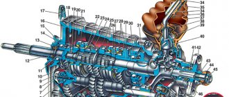
In general, the concept of “remaking” the box is not entirely correct, since the design of the VAZ-2105 gearbox with 4 speeds was practically no different from the same gearbox 2101. The 2105 gearbox has a three-shaft layout, with constant gear meshing and manual control. Externally, the Kopeika and Pyaterki checkpoints can be distinguished almost only by the markings on the body of the box.
The VAZ-2105 gearbox diagram with 4 stages is presented below, and structurally it does not differ from modifications 2101 and 2106:
| 1 | Bottom cover; | 40 | Needle bearing of the front end of the secondary shaft; |
| 2 | Filler and inspection plug; | 41 | Synchronizer spring thrust washer; |
| 3 | Intermediate shaft second gear gear; | 42 | Fourth gear synchronizer ring gear; |
| 4 | Intermediate shaft third gear gear; | 43 | Sliding clutch for synchronizer of third and fourth gears; |
| 5 | Intermediate shaft; | 44 | Third and fourth gear synchronizer sliding clutch hub; |
| 6 | Front intermediate shaft bearing; | 45 | Synchronizer retaining ring; |
| 7 | Clamp washer bolt; | 46 | Synchronizer locking ring; |
| 8 | Intermediate shaft front bearing clamp washer; | 47 | Synchronizer spring; |
| 9 | Intermediate shaft constant mesh gear; | 48 | Third gear synchronizer gear and ring gear; |
| 10 | Constant mesh gear of the input shaft; | 49 | Second gear synchronizer gear and ring gear; |
| 11 | Spring washer; | 50 | Secondary shaft; |
| 12 | Retaining ring; | 51 | First gear synchronizer gear and ring gear; |
| 13 | Rear input shaft bearing; | 52 | First gear gear bushing; |
| 14 | Input shaft oil seal; | 53 | Secondary shaft intermediate bearing; |
| 15 | Transmission front cover; | 54 | Intermediate bearing lock plate; |
| 16 | Bearing mounting ring; | 55 | Secondary shaft reverse gear; |
| 17 | Clutch housing; | 56 | Elastic cushion for gear shift lever damper; |
| 18 | Gearbox input shaft; | 57 | Damper rubber bushing; |
| 19 | Reversing light switch; | 58 | Damper spacer; |
| 20 | Intermediate shaft reverse gear; | 59 | Damper locking sleeve; |
| 21 | Reverse intermediate gear; | 60 | Inner gear shift lever cover; |
| 22 | Reverse fork; | 61 | Secondary shaft rear bearing oil seal; |
| 23 | Gear shift lever release spring; | 62 | Flange of the elastic coupling of the propeller shaft; |
| 24 | Tension spring bolt; | 63 | Screw; |
| 25 | Gear shift lever guide cup; | 64 | Centering ring seal; |
| 26 | Ball joint of the lever; | 65 | Centering ring retaining ring; |
| 27 | Spherical washer; | 66 | Centering ring; |
| 28 | Spring; | 67 | Rear secondary shaft bearing; |
| 29 | Gear shift lever; | 68 | Drain plug; |
| 30 | First and second gear shift fork; | 69 | Mud deflector; |
| 31 | Third and fourth gear shift fork; | 70 | Speedometer drive gear; |
| 32 | Fork rod for first and second gears; | 71 | Speedometer drive; |
| 33 | 3rd and 4th gear fork rod; | 72 | Rear gearbox cover; |
| 34 | Locking blocks; | 73 | Reverse idler gear axis; |
| 35 | Reverse fork rod; | 74 | Rear intermediate shaft bearing; |
| 36 | Rod lock ball; | 75 | Intermediate shaft first gear; |
| 37 | Retainer spring; | 76 | Gearbox housing; |
| 38 | Retainer cover; | 77 | Sliding clutch for synchronizer of first and second gears. |
| 39 | Breather; |
Reference by topic:
Wiring diagram of the VAZ-2104 car (injector, carburetor)
Since the box from the VAZ-2105 is structurally similar to the 2101, the kinematic diagram of the gearbox is the same. But the gear ratios are different; on 2105 gearboxes they are:
- 1st – 3.67;
- 2nd – 2.10;
- 3rd – 1.36;
- 4th – 1.00;
- Rear – 3.53;
As for the differences in the design between gearboxes 2105 and 2101, they mainly come down to different numbers of teeth on different gears. So, on the intermediate shaft of the gearbox, a 1st speed gear with 14 teeth is used (15 for 2101), and their inclination angle is greater. The constant mesh gear of this shaft has 28 teeth (29 for 2101). The input shaft uses an 18-tooth gear (19 for 2101). Because of these features, the shafts with gear blocks of these two gearboxes are not interchangeable if you try to install them separately. But in the case of a complex replacement - the input shaft along with the intermediate shaft and all gear blocks, then installation is quite possible. As for the secondary shaft, modification 2105 differs from shaft 2101 in the first gear gear (its teeth have a different angle, although their number is the same, and its diameter is also slightly larger).