External lighting switching diagram
2 – engine compartment lamp; 3 – battery; 4 – generator; 5 – reverse light switch; 6 – fuse block; 7 – indicator lamp for external lighting in the instrument cluster; 8 – glove box lighting lamp; 9 – instrument cluster lighting lamp; 10 – plug socket for a portable lamp; 11 – instrument lighting switch; 12 – external lighting switch; 13 – brake light switch; 14 – ignition switch; 15 – lamp switches located in the front door pillars; 16 – lamp switches located in the rear door pillars; 17 – lampshades; 18 – trunk lighting lamp; 19 – rear lights; 20 – license plate light; 21 – reversing lamp
Modification of the PC-57 turn relay | Cheerful Pencil
Technical evolution, technological progress - all this is good and wonderful. But when you have reliable, albeit old, equipment in your hands, equipped with the simplest electrical equipment, it does not calm you down for long. The reliability of the same equipment drops significantly if its production itself is treated as a handicraft and carelessly.
The old T-40 tractor is minimally equipped and few people do not know this. You can install any electrical equipment on it, creating comfort in operation and providing full detail of the operation of the engine and the unit as a whole. Is this just for everyone?
Yes. It was possible to install any electronic breaker relay or contact-transistor turn relay from modern technology, but any type of electronics had to be abandoned. Owner's wish. Everything is minimal and simple.
We settled on one of the 1984 PC57s. The principle of its operation is very simple, but this simple work was not performed by this relay. I will dwell on this very briefly.
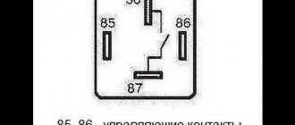
In order for the relay to operate immediately after voltage is applied to it, and for the operating periods to be the same, it is necessary that an electromagnetic field be present in the relay core with a force sufficient to reliably hold the moving armatures with commutating contacts to the yoke of the core.
The magnetic field in the relay coil is also present at those moments when its switching contacts are open, but it is so weak that it is not enough to attract the armatures to the core. In our case, the electromagnetic field was weak even when the contacts of the control pair were closed with a lowering resistance shunt.
The magnetic field of a coil depends both on the amount of current flowing through it and on the number of turns forming the coil itself.
Typically, for light signaling of direction indicators, two 21 W incandescent lamps are required, not counting repeater lamps. The control lamp does not count, since it operates from a different contact group of the relay and is not connected to the relay coil.
In our problematic case, the PC57 relay taken for installation refused to work even when connecting four 21 W lamps (4X21) and two 55 W lamps (2X55), not to mention the control lamp. But how will it work if the number of turns of the core coil is less than the calculated one? So we had to add the same number of turns of wire to the existing coil. Simple and accessible.
Windshield wiper connection diagram
1 – generator; 2 – battery; 3 – ignition switch; 4 – windshield wiper switch; 5 – windshield wiper relay; 6 – windshield wiper gearmotor; 7 – thermobimetallic fuse; 8 – windshield wiper switch located in the windshield washer pump; 9 – fuse block; A – the order of conditional numbering of the plugs in the relay blocks and the wiper gear motor
Turning relay VAZ 2101 replacement with an electronic relay.
If desired, you can replace the electromagnetic-thermal relays of the VAZ 2101 with an electronic relay used on VAZs of subsequent brands. The connection is made in almost the same way. In addition to the standard wires, it is necessary to add only one wire connecting the electronic relay to the vehicle ground. In this case, you can also connect an alarm button.
Electrical circuit diagram for VAZ-21011, VAZ-21013 cars
1 – headlights; 2 – front direction indicators; 3 – side direction indicators; 4 – battery; 5 – battery charge warning lamp relay; 6 – relay for turning on low beam headlights; 7 – relay for turning on the high beam headlights; 8 – generator; 9 – starter; 10 – engine compartment lamp; 11 – spark plugs; 12 – oil pressure warning lamp sensor; 13 – coolant temperature indicator sensor; 14 – sound signals; 15 – ignition distributor; 16 – windshield wiper gear motor; 17 – brake fluid level warning lamp sensor; 18 – ignition coil; 19 – electric motor for windshield washer; 20 – voltage regulator; 21 – heater electric motor; 22 – glove box lighting lamp; 23 – additional resistor of the heater electric motor; 24 – plug socket for a portable lamp; 25 – parking brake warning lamp switch; 26 – brake signal switch; 27 – relay-interrupter of direction indicators; 28 – reverse light switch; 29 – fuse block; 30 – relay-interrupter for the parking brake warning lamp; 31 – windshield wiper relay; 32 – heater motor switch; 33 – cigarette lighter; 34 – lamp switches located in the rear door pillars; 35 – lamp switches located in the front door pillars; 36 – lampshades; 37 – ignition switch; 38 – instrument cluster; 39 – coolant temperature indicator; 40 – control lamp for high beam headlights; 41 – indicator lamp for external lighting; 42 – turn signal indicator lamp; 43 – battery charge indicator lamp; 44 – oil pressure warning lamp; 45 – control lamp for parking brake and brake fluid level; 46 – fuel level indicator; 47 – fuel reserve warning lamp; 48 – instrument cluster lighting lamp; 49 – headlight switch; 50 – direction indicator switch; 51 – sound signal switch; 52 – windshield washer switch; 53 – wiper switch; 54 – external lighting switch; 55 – instrument lighting switch; 56 – sensor for level indicator and fuel reserve; 57 – trunk lighting lamp; 58 – rear lights; 59 – license plate light; 60 – reversing light
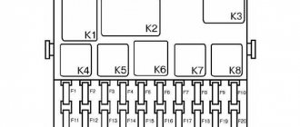
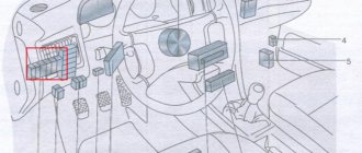
Relay under the hood
Several relay elements are located in the engine compartment.
Turn signal and hazard warning relay
The turn signal and hazard warning relay (RS-491) is located on the bulkhead under the instrument cluster.
Headlight and battery charge relay
Scheme
Purpose
- Battery charge indicator relay (PC-702)
- Headlight high beam relay (VAZ-21011 and BA3-21013)
- Relay for low beam headlights (VAZ-21011 and BA3-21013)
1) Relay RS-702 is used to turn on the warning lamp on the instrument panel when the generator voltage is insufficient to charge the battery.
2) Headlights. On cars 2101 and 2102, as well as 21011 produced before 1980, the headlights are turned on by a switch located on the steering column when the exterior lighting switch is on. On cars 21011 produced since 1980 and on cars 21013, the headlights are turned on by the same switches, but through auxiliary relays.
Still have questions? Ask them in the comments.
Turning relay malfunctions and ways to eliminate them
Turn relays of all types have fairly high reliability, but these components are not immune to breakdowns. Typically, the failure of this relay makes it impossible to turn on the direction indicators, or disrupts their operation - they may be constantly on, blink too quickly or too slowly, etc.
The turn relay is a non-repairable part - if it malfunctions, this relay is simply replaced with a new one. Today, the price of VAZ turn signal relays is very affordable, so many drivers take them for future use, and in the future there are no problems with repairing and finding this component.
The warm season, especially spring and summer, is the season for cycling, nature walks and family holidays. In the AvtoALL.RU online store you will find everything to make your vacation enjoyable and useful.
The May holidays are the first truly warm weekend, which can be usefully spent outdoors with family and close friends! The range of products from the AvtoALL online store will help you make your outdoor leisure time as comfortable as possible.
It's hard to find a child who doesn't like active play outside, and every child has dreamed of one thing since childhood - a bicycle. Choosing children's bicycles is a responsible task, the solution of which determines the joy and health of the child. Types, features and selection of a children's bicycle is the topic of this article.
The warm season, especially spring and summer, is the season for cycling, nature walks and family holidays. But the bike will be comfortable and bring pleasure only if it is chosen correctly. Read the article about the choice and features of buying a bicycle for adults (men and women).
Swedish Husqvarna tools are known all over the world and are a symbol of true quality and reliability. Among other things, chainsaws are also produced under this brand - read all about Husqvarna saws, their current model range, features and characteristics, as well as the issue of choice in this article.
Heaters and pre-heaters from the German company Eberspächer are world-famous devices that increase the comfort and safety of winter operation of equipment. Read the article about the products of this brand, their types and main characteristics, as well as the selection of heaters and preheaters.
In general, relay 6422.3747 was purchased. how to connect - idk. There are no wiring diagrams on the internet. On the pins there are only numbers 1, 2, 3 and 4. Please tell me.
Electronic relay: circuit and principle of operation
The design of the electronic rotation relay consists of two main parts. From a standard electromagnetic relay that performs switching to an electronic key that provides a certain frequency of operation of this device.
The nichrome cord has been replaced with an electronic key. With its help, voltage is applied and removed from the winding of the electromagnetic relay at certain intervals. The key is built on microcircuits or discrete elements. They are components of the main generator and control circuits.
The operating principle of an electronic relay is very simple. When voltage is applied to the relay, the master oscillator is activated. With its help, control pulses with different frequencies are generated, which enter the control circuit. With the help of pulses, the current flowing through the coil of the electromagnetic relay is supplied or interrupted. Such actions also cause the anchor to retract or sink. As a result, the contact groups close or open at a certain frequency, which gives the same blinking as indicator lights.
All electronic elements of the relay are mounted on a separate board. An electromagnetic relay is located above the board. Both are housed in a plastic case. The contacts are thrown out from below or to the side. There are holes and tabs for bolt connections to secure the housing.
Each electronic rotation relay has undeniable advantages over other designs. High-quality and technologically advanced devices manufactured on the basis of modern circuits and characterized by increased reliability have proven themselves. The technical characteristics of these devices remain unchanged regardless of their service life.
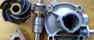
DIY turn relay
Sometimes situations arise when the standard turn signal relay fails and a new device cannot be purchased. In such a situation, you can try to make a turn signal relay with your own hands to provide the car with the necessary signals. The simplest electronic devices that you can make yourself are simple and easy to use, operate smoothly and reliably. High precision is achieved through the use of PWM controllers used in all circuits.
The simplest replacement for an electromagnetic relay is designed for a maximum load power of 150 W. It is connected to the positive air gap. If the IRFZ44 field switch is replaced with the IRF3205 model, 200 W can also be connected. This simple circuit guarantees high accuracy. The blinking frequency does not depend on the power of the lamps, so LED, halogen and other lamps can be included in the circuit.
The blinking frequency is directly related to the capacitance of the capacitor. As the capacity increases, the indicator will blink less frequently, and conversely, decreasing the capacity will cause it to blink faster. The low-power 1n4148 diode can be replaced with any similar element. When the circuit reaches 80 W, a small amount of heat is observed in the FET area. This means it is ready to use.
There is another simple gear shift relay circuit with a coil - simple, reliable and inexpensive. It is capable of turning on both conventional and LED lamps and is designed for a voltage of 12 V. The contacts are connected according to the principle of a regular switch, that is, in series with the light bulb. The LED is installed in the circuit as an indicator during commissioning. The device parameters are regulated by changing the resistance of the resistor.
What You Need to Know About Automotive Wiring Diagram
Information on electrical equipment can additionally be downloaded in one archive with the VAZ wiring diagram. Basic Soviet VAZ sedan with a 1.0 engine.
Plug socket for portable lamp. Windshield washer motor. VAZ generator
Indicator lamp for VAZ direction indicators Features of the electrical circuit of VAZ cars The electrical circuit of the front part of the cars and the installation of the front bundles of wires on VAZ and VAZ cars are the same.
In order to properly operate any vehicle, you must first study all its technical characteristics and, of course, its electrical circuit. Thus, each graphical diagram of an automobile electrical circuit must include images of elements of three categories: Power sources, for example, galvanic cells, their function is to generate electric current. In the case of a large number of different elements, the routes are depicted in segments, with the obligatory indication of the places of breaks and connections on the diagram.
See also: From 34 45 51 300 97 status
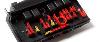
Fuses for VAZ 2101, 2102
The main bundle of wires is the front one. Rear bundle of wires of a VAZ car. Front bundle 12 has three main branches. Since electric current of varying strength flows through different wires, the cross-section of the wire strands is also different.
Therefore, the negative terminals of all instruments and actuators had to have high-quality contact with the metal body. Distributor. Fuse box. Engine compartment At the request of Soviet engineers, Fiat specialists redesigned some components in the engine compartment. Windshield wiper relay.
Therefore, we have before us one of the first mass schemes, which was transferred practically unchanged from the Fiat car to the VAZ Zhiguli. Therefore, VAZ and VAZ cars of the same year of production have no differences in the electrical circuit of the front part of the cars. Parking brake warning light relay.
Battery wire bundle. Modifications of a VAZ car VAZ spark plugs Over the years of operation of the car, most likely, a lot of changes have been made to the circuit, so it can be quite difficult to restore the original state of the electrical equipment. Everything about replacing the VAZ 2101 wiring and other useful information.