Malfunctions of VAZ transfer cases
The transfer case is not present in all VAZ passenger cars, but only on cars with two drive axles.
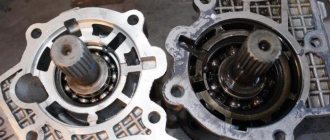
In the transmission, the transfer case (TC) is installed at the rear of the gearbox; a rear driveshaft is attached to its shank, which connects the transfer case to the rear axle. The front axle is also driven by the steering wheel; it is connected to the transfer case by a front driveshaft. The reduction gear in the Republic of Kazakhstan is designed to obtain high torque, it is used to overcome difficult sections of the road, and helps to cope with off-road conditions. The VAZ Niva transfer case contains the following main parts:
- the body itself;
- front axle drive shaft;
- intermediate shaft;
- drive shaft;
- gears;
- bearings;
- differential housing;
- satellites;
- differential lock clutch;
- gear shift clutch;
- flanges (for connection to cardan shafts);
- oil seals;
- control levers.
The transfer case on the Niva is a fairly reliable unit; problems with repairs in the mechanism itself arise mainly due to insufficient oil level in the valve - if for some reason the oil leaks out, intensive wear of all parts occurs. Among the frequently occurring malfunctions are:
- vibration in the body at various speeds when the car is moving;
- vibration when the vehicle starts moving;
- noise in the transfer case when the car is slipping or turning;
- difficult upshift or downshift, difficult engagement of the lock.
- the body itself;
- front axle drive shaft;
- intermediate shaft;
- drive shaft;
- gears;
- bearings;
- differential housing;
- satellites;
- differential lock clutch;
- gear shift clutch;
- flanges (for connection to cardan shafts);
- oil seals;
- control levers.
A violation of the normal operation of the VAZ-21213 transfer case can be assumed by the following signs:
- Delays when connecting front-wheel drive.
- Transfer case overheating.
- High transmission oil consumption.
- Spontaneous disconnection of the front axle.
The transfer case is replaced when the old unit becomes beyond repair and is recommended to be done in an inspection pit.
Procedure:
- Remove the cover, which is located on the floor tunnel where the switching elements are installed. To do this, unscrew the 4 screws.
- Unscrew the 3 self-tapping screws designed to secure the trim under the arms. Pull out the levers and remove the trim along with them. Disconnect the wires that appear in the special hole.
- Disconnect the driveshaft from the transfer case. To do this, you can use a 13mm wrench. Unscrew the special locking nut and pull out the speedometer cable.
- Disconnect the gearbox drive shaft from the transfer case. Thus, we exempt her from the checkpoint. Remove the transfer case by unscrewing the nuts of the special suspension device.
- Install the new unit in reverse assembly sequence.
This completes the replacement and repair of the Niva transfer case. As you can see, this is not a complicated operation and is performed on your own in the conditions of an ordinary garage. Thus, you can save a lot of money on the services of car service specialists.
How to eliminate cardan vibration Correct installation of the transfer case (centering)
See also Causes of transfer case vibration
After the second transmission overhaul, immediately after the first - elimination of defects under warranty, strong vibration appeared at approximately 100 km/h. Suspicion immediately fell on the front driveshaft, in which the crosspiece was changed along with the transmission bulkhead. A test with the removal of the cardan confirmed this version - there was no vibration on the “rear-wheel drive”.
But nothing ended there; on the contrary, miracles began. Re-pressing the crosspiece with careful selection of retaining rings, extrusion, led only to a slight decrease in vibration, but that’s all... It is clear that the “debugging” took quite a long time.
In the meantime, the crosspiece (new! - within a month!) completely died due to vibration, although I tried to drive in “gentle” modes.
The next step - replacing the cardan (this time I took an Izhevsk one, 2 times cheaper than the original one, since there were still doubts about the feasibility of the replacement) - did not radically solve the problem, the vibration remained, although it became a little less.
Centering the transfer case, this way and that, also did not help, and an interesting effect appeared - both the intensity of the vibration and its character changed, the range of speeds in which it occurred changed, various signs alternately pointed either to the cardan shafts or to the shaft.
Finally, one of the flames on auto.ru reminded me of a “favorites” bookmark on the Internet.
You can use a tape measure to measure the distance between the edges of the flanges in different positions, top-bottom, right-left. The angle between the flange planes (or, equivalently, the RK and RPM axes - front cardan) is approximately equal to: (delta beta)
arcsin(dL / 2R), where
dL = d1 – d2 – difference in measured distances between flange edges,
R – flange radius
Due to the fracture of the cardan, it is impossible to tension the tape measure between the flanges - the housing is in the way. Therefore, it is necessary to make two completely identical (this is important! otherwise the results will be distorted) metal plates, screw them onto the cardan flanges, unscrewing one of the 4 fastening bolts, and measure the distance between their edges. The larger the radius at which measurements are taken, the higher the accuracy.
The records I made are about 53 mm long. The total diameter of the flange with plates is exactly 160 mm (R=80 mm). The permissible deviation at an angle between the flange planes of 1 degree is equal to:
dL = 2R * sin(delta beta) = 2*80* sin(1) = 2.79 mm
We hang the front wheel so that the cardan can rotate. We place a jack (conveniently hydraulic) under the lower suspension arm so as not to “twist the body.” Here
now you can use it under your car...
| 1. Shims and plates | 2. Plate on the transfer case flange | 3. Plate on the RPM flange |
You can’t get to the top edge of the cardan with a tape measure, but that’s okay. Three measurements (left, right and bottom) are more than enough.
| 5. Measure from the right |
6. We measure from below
Looking ahead, I will say that everything took almost 4 hours. Mainly because at first I tried to calculate the necessary actions logically, solving the “8 nuts problem in three dimensions” in my head. But the result often turned out to be far from expected. Then I simply ignored the calculations and began to act through the usual enumeration of options.
Let’s just say, I let go of one side of the steering wheel a third of the way through the hairpin, twisted the shaft in 5th gear with the steering wheel in neutral, and saw what happened. Then another third - and so on. It is clearly noticeable how, at the first moment of engaging the clutch, a characteristic short-term vibration occurs while the transfer case, lowered and hanging on the rubber coupling, is centered and moved back, compensating for the new angle.
This had to be repeated many times until the necessary gaps were found between the body and the gearbox support, the body and the gearbox brackets, different on the right and left, by the way. It should be noted that “dynamic centering” is quite rough, in the sense that there are many positions of the steering wheel in which there will be no vibration with the transfer case in neutral.
Therefore, you don’t have to be shy and leave the engine in gear, go down into the pit and use your handles to push the transfer case in the right direction. And so many, many times, until one day the measurements give an acceptable result, and there is no vibration in neutral.
I was never able to completely reduce the discrepancies to zero; the difference at three points in the end did not exceed 2 mm. Then you need to fill the gaps with the required number of shims, once again make sure that there is no vibration in the neutral, take the final measurements and tighten the nuts.
There is no point in doing this with the rear cardan (on the Crocodile), because it is connected to the transfer case through an intermediate shaft with a CV joint.
Transfer case Niva 21213
Model VAZ-21213 is an all-terrain passenger car with permanent all-wheel drive and differential lock. Brand 21213 is a restyled version of the first VAZ SUV, VAZ-2121. RK Niva 21213 has three gears:
- the first - with a gear ratio of 1.2;
- the second, lowered – with the number 2.135;
- neutral
21213 is equipped with 4-speed and 5-speed gearboxes, and when the first speed of the transfer case is turned on, the car operates in standard mode, the gear ratios in the transmission are from 5-speed. The checkpoints are as follows:
- 1 – 4,4;
- 2 – 2,52;
- 3 – 1,63;
- 4 – 1,2;
- 5 – 0,98.
When you turn on the second position of the transfer case lever (reverse position), the gear ratios change (lower):
- 1 – 7,83;
- 2 –4,48;
- 3 – 2,90;
- 4 – 2,14;
- 5 – 1,75.
On ordinary roads, the transfer case is always in first gear, the transfer case control lever (reduction gear) is pushed forward. The neutral gear of the RK disconnects the transmission, and in this position the car does not drive; there is also a neutral in the gearbox.
Motorists often ask the question: why is neutral gear needed in a transfer case? The neutral is used when connecting additional units to the transmission, for example, a mechanical winch; in this case, a power take-off must also be installed.
Also interesting: Why does the laptop sometimes charge and sometimes not? — Habr Q&A
Video - Aligning the transfer case Niva Chevrolet 2123
The transfer case of the VAZ 2123 car has fundamentally the same device as unit 21213/21214, but in the Chevy Niva:
- different control mechanism (with one lever);
- an additional support was installed (on a simple Niva the RK is mounted on two supports, on a VAZ 2123 car - on three supports).
2. Floor vibration, which occurs when driving at a speed of approximately 100 kilometers per hour. Occurs in the area of the front seats.
- There was a strong imbalance of the intermediate shaft. This happens as a result of incorrect assembly of the unit or severe wear of individual elements. In this case, it is necessary to replace the entire intermediate shaft.
- there has been a change in shape or fracture of the bolts securing the elastic coupling. As with the first malfunction, simply replace the damaged fasteners. If possible, it is recommended to replace the entire intermediate shaft assembly.
- CV joint wedging. This hinge must be disassembled and the amount of lubricant in it checked. The lost lubricant is restored, and if necessary, the CV joint must be completely replaced.
- wedging of the hinges on the front and rear shaft driveshafts. In this case, lubricate the unit; if this does not help, then the universal joint or the corresponding shaft must be completely replaced.
- there is a large imbalance of the driveshaft. Replace the faulty shaft assembly.
- severe violation of the alignment of the special center differential. Such a malfunction can only be eliminated by replacing the unit.
3. Noise from the unit when entering sharp turns or during free rotation of the wheels.
- The special teeth of the satellites or the gears located in the drive of the drive axles have undergone increased wear. Old parts need to be replaced.
- The satellites rotate too hard. Disassemble the mechanism and check for smoothness. If various burrs are found on the satellite teeth, remove them by grinding.
- the spherical or internal cavity of the differential has suffered severe wear. In this case, the differential housing or the entire assembly is replaced.
- The gears in the differential housing began to jam. Replace worn parts and create an axial clearance of 0.10 millimeters.
- The axial clearance between the gears is damaged. Restore the gap by selecting special support washers located in the drive part of the bridge. Be sure to monitor the resistance to rotation to avoid excessive friction between parts.
4. Difficulty shifting gears or setting differential operating modes.
- The sliding shift clutch located on the hub splines or differential housing moves too hard. Replace the parts that have wrinkled splines, and clean the rest with a file to remove burrs.
- The fork or gearshift rod has been severely deformed. The part can be straightened or simply replaced.
- The drive lever was damaged. In this case, it needs to be changed or simply straightened.
- There is a slight jamming of the special levers of the drive mechanism located on the axles. Disassemble the mechanism and check its internal condition. If necessary, carry out a complete cleaning or replace faulty or deformed elements.
- The oil that is poured into the unit is too thick. Fill in oil that matches the climatic conditions of the vehicle.
5. Spontaneous, without driver intervention, turning off or resetting gears, as well as the differential locking mechanism.
- mechanical damage or deformation of teeth. Sand or replace damaged transmission parts.
- The elasticity of the springs of the special handle position clamps is broken or the clamps are clogged with dirt. Clean the retaining devices or replace the springs.
6. There is an oil leak from the transfer case.
- wear of sealing seals of rotating parts. Replace worn rubber elements and add oil to the required level.
- The fastening parts of the oil pan have been weakened. Tighten them and, if possible, replace the gasket.
How to use a transfer case in a field, box design
The relatively complex scheme for distributing torque from the internal combustion engine to the wheels is explained by the universal purpose of the Niva 2121 - if used correctly, it can be used comfortably in the city and along muddy country roads.
Such properties are ensured by the presence of a transfer case with a center differential lock, complementing a 4- or 5-speed manual transmission, depending on the year of manufacture.
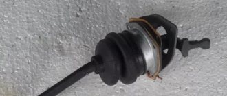
The lever, located closer to the dashboard , is responsible for turning off/on the center differential, the second “small” lever controls the range multiplier and has 3 positions: high and low rows, as well as neutral.
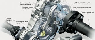
Design and principle of operation of the Niva 2121 transfer case
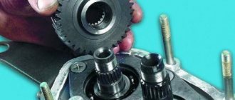
The transfer case mechanism includes more than 60 independent parts, which is confirmed by the presented drawing. Therefore, it is quite prudent to name the main elements and their purpose.
A pair of gears are tightly seated on the drive shaft, one of them (large) is intended for high gear, the second (small) is responsible for low gear. They have serrations with straight and oblique profiles.
The first ones are in contact with the coupling, the second ones - with the intermediate shaft.
The inclusion of one or another row causes the coupling to move along the hub in the horizontal direction, after which it is connected to the gear on the transfer case drive shaft.
The intermediate position turns off the gearbox ( the gearbox is open ), and the vehicle cannot be moved in this mode. The front helical gear on the intermediate shaft is used to control the differential.
The locking is engaged, or the rigid coupling of the drive shafts of both axles, is carried out through a clutch. The design is typical for modifications 21213 and 21214, and the latter is additionally equipped with a speed sensor drive.
How to use a transfer case with a range multiplier on a Niva 2121
The normal position for the RK handles, ensuring adequate behavior on the road of good quality:
The special operating mode of the transmission is switched on not long before the car begins to overcome an obstacle (rut, mud, ford or rise). The transition to the lowest row must be done while stopping. Returning to top gear is allowed on the go, although it causes problems for beginners due to the lack of the usual synchronizer.
It is somewhat more difficult to properly handle the forced manual locking of the center differential. On the contrary, it turns on when the car moves slightly (up to 20 km/h) due to misalignment of the grooves on the locking clutch, satellites and ring gear.
To simplify turning the lever into the desired position, taking into account the Niva 2121 transfer case, pick up a small speed, then, shaking the steering wheel, pull the handle towards you.
Problems can also arise when disengaging the lockout, as the clutch teeth literally catch on the ring gear. Engage reverse and, rocking the steering wheel, push the lever away from you. This action is performed immediately after overcoming a difficult section in order to avoid overloading the gearbox.
It is most effective to disable the differential together with the transition to lower stages. In this case, only diagonal suspension of the wheels can stop a Niva 4x4, since standard inter-wheel locking is not provided. When performing the above operations, you must not give free rein to physical strength.
An attempt to “push” the transmission will most likely result in expensive repairs.
Possible problems
Harsh operation and insufficient attention to how to use the transfer case on the Niva 2121 lead to the appearance of:
Experience shows that the culprits are: insufficient oil level, incorrect centering of the steering wheel, loosening of the support fastenings and damage to the rubber bands. An additional influence is exerted by the condition of the cardan and the engine itself.
Eliminate vibration with additional fasteners
Vibration in the body is the main “disease” of the Niva; it often occurs due to improper alignment of the transfer case. Most often, vibration occurs on VAZ 21213/21214 cars, since the transfer case is mounted only on two supports on the sides of the body; on the Chevrolet Niva, the transfer case is already installed on three supports.
- driveshafts are poorly secured;
- wheels are not balanced;
- there is play in the cardan crosspieces (vibration is especially affected by play in the rear driveshaft crosspieces);
- The vibration comes from the engine itself.
Also interesting: How to make a transfer case subframe for a Niva with your own hands
Vibration when starting off on a Niva can also occur for the following reasons:
- the mounting supports of the transfer case have become loose;
- The rubber on the RK supports themselves broke.
Installing the third support of the transfer case on VAZ 21213/21214 vehicles allows you to reduce the level of vibration of the transfer case; with this support it is easier to center the transfer case. The part can be purchased at auto stores or made yourself. The finished product comes with three long studs (for model 2121); to install the third support on this machine, you will need to unscrew the short studs from the transfer case housing and install new studs from the kit. We carry out repairs as follows:
- dismantle the front passenger seat in the cabin;
- remove the floor tunnel lining;
- in the cabin we move aside the carpet covering the body amplifier (in front of the handbrake lever);
- remove the transfer case (alternatively, you can simply hang it up, but removing the third support makes it easier to install);
- We attach the bracket of the new support to the body of the RC;
- we install the transfer case in place, center it in the optimal position, and fasten the side supports;
- we combine the third support with the body, drill two holes in the bottom;
- Using washers, bolts and nuts (from the kit) we attach the support to the bottom of the body.
Vibration is eliminated more effectively by installing a subframe under the transfer case. You can also make such a device yourself or buy a finished product at a car store.
In order to install the subframe, the transfer case must be removed. It is more convenient to carry out such work in a pit; we carry out repairs as follows:
- leave the car in neutral gear;
- disconnect the propeller shaft from the transfer case, it is advisable to mark the driveshaft flange and the drive shaft so that during installation, align the driveshaft according to the marks - this way, the occurrence of unnecessary vibrations is eliminated;
- dismantle the muffler mounting bracket;
- remove the gearbox traverse;
- jack up the transfer case, remove the side fastenings of the transfer case;
- We treat the places where the subframe fits to the body with Movil;
- place the subframe on the gearbox studs;
- we mark the attachment points of the subframe on the side members, drill holes, attach bolts to the body;
- we tighten all fastenings, except for the transfer case supports themselves;
- we perform alignment of the steering wheel;
- Finally tighten the transfer case supports.
It should be noted that installing an additional support or subframe on the steering wheel does not always lead to the desired effect; in some cases, vibration only increases.
Niva transfer case alignment
Correct installation of the transfer case can be done in several ways. Most often in auto repair shops, repairmen use the following method:
- hang the car on a lift;
- loosen the transfer case;
- start the engine;
- engage the gear and accelerate the car according to the speedometer to the speed at which vibration occurs (often it occurs at speeds from 40 to 80 km/h);
- without using the brakes, reduce the engine speed, then turn off the ignition.
The transfer case itself is centered in place, all that remains is to tighten the fastenings of the supports.
You can also adjust the position of the RC using a wire; we do it as follows:
- loosen all four fastenings of the transfer case supports;
- fasten one end of the wire to the rubber coupling of the propeller shaft;
- we attach another piece of wire to the CV joint, bring the other ends of the wire to each other;
- rotate the shaft; if the transfer case is not centered, the ends of the wire will diverge during rotation;
- the task comes down to installing the transfer case using the selection method so that the ends of the wire practically do not diverge from each other in any position when turning the shaft.
For a long time, drivers of Soviet Nivas have been convinced that aligning the car’s transfer case significantly reduces vibration, noise levels in the cabin and saves fuel consumption. Therefore, if you have just purchased a VAZ-21213, then you should immediately start this work. When you purchase a car second-hand, you should not rely on all the promises and assurances of the previous owner.
Also interesting: VAZ 2121 how to change silent blocks to
Even if he assured that the alignment was carried out and everything was fine, it is best to check this fact and make sure of it. This work in itself is not difficult, but it requires additional hands, since the presence of an overpass cannot be done alone. Car service specialists recommend using a lift, because other devices require additional fastenings. The process itself is like this:
- one person sits in the driver’s seat, the car is lifted with him;
- the lock must be disabled and 4th or 5th gear engaged;
- it is necessary that the pins are in the middle of the support holes (to do this, move the dispensing supports apart with your hands);
- the second person from below must loosen the 4 nuts that secure the transfer case;
- the person in the driver’s seat must pick up speed and inform his partner about this (the assistant “on the go” tightens the clamps to the required level);
- in a car service center for centering, the car must pick up speed to 60 km/h (the speed must be set in 4th gear).
It is important to know! On Niva 21213, the intermediate shaft is not a cardan, but a CV joint. For this reason, factory settings may dispense with height adjustment. But in the case when the dynamic alignment does not live up to expectations, you can try to tighten or lower the transfer case and repeat the alignment.
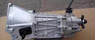
Video - Do-it-yourself disassembly of Niva 21214 transfer case
There is nothing fundamentally complicated in the design of the multiplier, except that it itself is not attached to the main gearbox as on more modern all-terrain vehicles. Intermediate driveshafts extend from the transfer case to the manual transmission. The rest of the device is represented by gears, satellites and bearings. The design also includes a free differential with locking.
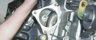
To repair the transfer case on a VAZ 21213 (21214), the unit must first be removed. We carry out removal in the following order:
- in the cabin we dismantle the plastic lining of the gearbox and gearbox levers;
- unscrew the knobs of the transfer case shift levers, remove the casing under them;
- disconnect the speedometer cable, for RK 21214 you will need to additionally disconnect the speed sensor;
- we unscrew the bolts with nuts securing the elastic coupling of the front and rear propeller shafts; in order to remove the bolts, the cardan shafts must be turned - they are removed one at a time in one specific position of the shaft;
- We install a jack (or other support) under the transfer case and mark the places where the side supports of the RC were attached. This is done in order to minimize the alignment of the transfer case during installation;
- unscrew the 4 nuts securing the gearbox to the gearbox;
- unscrew the 4 fastenings of the RC supports to the car body;
- Now all that remains is to dismantle the transfer case.
Related articles:
Repair of transfer case on Niva 21213, how to center it, do-it-yourself adjustment with video
The transfer case of the Niva car and some other SUVs is designed to distribute the torque of the wheels both between the axles and between different wheels of the same axle. This is done in order to increase cross-country ability on particularly difficult sections of the route. In the language of specialists, this device is called a “demultiplier.”
Transfer case location and functions
Location of the transfer case in the Niva 21213
The transfer case occupies an intermediate position in the vehicle transmission between the gearbox and the driveshaft. It has its own body in which its components are located.
The transfer case helps to implement such SUV capabilities as:
- Center differential lock.
- Disabling the drive axle.
- Increased torque of the drive wheels.
- Distribution of torque along the wheel axles.
Possible signs of malfunction
A violation of the normal operation of the VAZ-21213 transfer case can be assumed by the following signs:
- Delays when connecting front-wheel drive.
- Transfer case overheating.
- High transmission oil consumption.
- Spontaneous disconnection of the front axle.
There is nothing fundamentally complicated in the design of the multiplier, except that it itself is not attached to the main gearbox as on more modern all-terrain vehicles. Intermediate driveshafts extend from the transfer case to the manual transmission. The rest of the device is represented by gears, satellites and bearings. The design also includes a free differential with locking.
Tools
- Spanner 13.
- Flathead screwdriver.
- Key for 10.
How to remove a box from a car
- The machine must be installed on an inspection hole or lift.
- The transfer case levers are set to the neutral position.
- The lining of the central floor tunnel is removed.
The tunnel cover must be removed to gain access to the transfer lever hatch - The handles and lever covers are removed.
The handles and covers of all levers can be carefully removed - The lever hatch cover is removed using four screws.
We get access to the insides of the transfer case - The speedometer drive is disconnected from the transfer case.
You need to remove the sensor connected to the speedometer from the transfer case. - The driveshafts are removed from the front and rear.
Cardan shafts fit to the transfer case front and rear - After unscrewing several fasteners, the transfer case housing is removed.
It’s enough to just push it forward a little (if you look in the direction of the car’s movement, backward) and down. We push with one hand and hold with the other. When removing the box, the main thing is not to overdo it
Installation, centering and adjustment
- Install the engine mount brackets correctly.
- Install the transfer case without fully tightening the bolts of its fastenings.
- The flanges of the drive shaft of the box must coincide with the intermediate driveshaft.
- Install the transfer case supports and secure the fasteners.
- Connect the transfer case to the front and rear universal joints, and reinstall the differential lock sensor.
Centering the range multiplier can be done in different ways. The classic version of alignment is that the car is installed on a lift or inspection hole, and all operations are performed by two people, one of whom is sitting behind the wheel. The procedure is performed as follows:
- Fourth gear is engaged and the lock is disabled.
We put the transfer case in neutral position, engage the 4th gear of the manual transmission - The transfer case mounting nuts are loosened under the car.
To center the range-multiplier, use a 15mm wrench to loosen the fastenings - The driver begins to accelerate the engine, informing his partner about this, who directs the box to the desired position.
The assistant gets all the brunt of the alignment work; strength and dexterity are needed here.
Repair and alignment of the transfer unit must be carried out subject to the presence of experience and knowledge in the field of design and repair of the specific transmission of all-wheel drive vehicles. The range-multiplier needs to be centered after each reinstallation. The correct position of the box is judged by the presence of vibration.
- Author: Konstantin Kostin