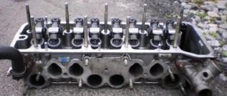
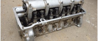
cylinder head VAZ 2106
The cylinder head is made of an aluminum alloy containing a certain percentage of copper and tin in order to give it softness and elasticity. With these properties, it is pressed tightly against the gasket, preventing gas breakthrough.
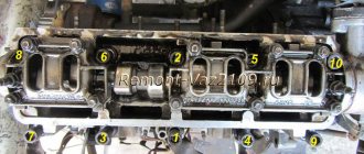
The entire head is attached to the cylinder block with eleven bolts, ten large and one small, which are tightened with a certain sequence and force.
Replacing the gasket
1. Remove the cylinder head from the engine complete with intake and exhaust manifolds.
2. Disconnect the wire from the negative terminal of the battery. Drain the coolant.
3. Remove the carburetor.
4. Remove the ignition distributor with high-voltage wires.
5. Remove the block head cover.
6. Remove the camshaft assembly with the bearing housing. Disconnect the exhaust system from the exhaust manifold and remove the coolant drain pipe from the heater radiator.
7. Remove the chain from the camshaft sprocket.
8. Disconnect the supply hose from the heater radiator pipe.
9. Remove the hoses from the two pipes of the cylinder head.
10. Using a 13mm wrench, unscrew the bolt securing the cylinder head near the ignition distributor.
11. Using a “12” socket, unscrew the ten bolts securing the head to the cylinder block.
12. Remove the bolts from the holes.
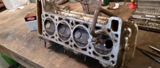
13. Remove the cylinder head assembly with manifolds
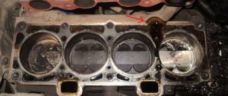
14. Then remove the head gasket.
15. Install the head in the reverse order. We replace the head gasket with a new one.
16. To center the gasket and head, two bushings are installed in the block.
17. Tighten the cylinder head bolts in two steps. First, tighten bolts No. 1–10 with a torque of 33.3–41.16 N.m, and then tighten them with a torque of 95.9–118.3 N.m. Lastly, tighten bolt No. 11 to a torque of 30.6–39 N.m.
What is the price for valve stem seals in the link.
Finalization
Removing the cylinder head (cylinder head)
We eliminate the shortcomings of the casting of the cylinder head and manifolds (we grind the cylinder head and combine the manifolds). Using cutters and sandpaper.
Fundamentally important: the inlet channels must not be polished! If the surface is polished (mirror-like), the mixture condenses on it and is written. We remove tides and irregularities in the channels.
We mill the cylinder head by 1 mm.
We wash the cylinder head with all available means (gasoline, kerosene, washing powder, etc.)
It's better to do this at home (at room temperature)
We check whether the valves are bent (we worked in vain for 4 hours). If necessary, we buy new ones and rub them in with lapping paste, applying drops to the supporting surface of the valves. For convenience, glue the 17 nut to the valve with superglue
We dry the valves by inserting new valve stem seals and install the rocker arms and manifolds with the carburetor so that all channels match perfectly
Then the work was created on the engine installed in the engine compartment
We install the cylinder head, and at the same time we definitely buy NEW cylinder head BOLTS (length 120mm). We observe the order and tightening torques.
Torque
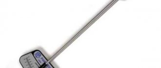
Take a torque wrench and tighten all the pins in the order shown in the diagram. In this case, the pulling torque should be 3.5 – 4.1 kgf*m. First of all, you need to tighten the two screws located in the middle. Then, in order to maintain the correct order, two upper and lower pins are tightened, located on each side of the middle elements. Next, the two outer pins are tightened - first the left ones, then the right ones. In this case, the element numbered eleven does not need to be touched.
After these steps are completed, you need to tighten the pins again, in the same sequence. Please note that now the tightening torque with a torque wrench should be 10.5 - 11.5 kgf*m.
After these steps, you only have to tighten screw number 11. Do this using a torque wrench, and the torque should be 3.5 - 4.0 kgf*m.
Take off
This procedure itself is not that complicated, but it does require a little preparatory work. And I’ll immediately give a list of the necessary tools, which you simply cannot do without when performing this repair:
Wrench with extension
Head for 19 and 10
Firstly, if you are going to repair the engine, then you must drain the coolant.
Then you need to remove the camshaft, since the cylinder head bolts are located right under it and it is simply impossible to get to them without removing the camshaft.
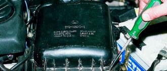
And it is also necessary to disconnect the coolant supply pipe to the head, which is located on the right rear side of the engine, as shown in the photo below:
And disconnect the tube, moving it slightly to the side:
You also need to disconnect the plug from the temperature sensor, which is shown in the photo:
Now everything is ready and you can begin to unscrew the bolts securing the cylinder head to the engine block, using a fairly powerful socket wrench:
Once the bolts have been loosened, you can use a ratchet handle to complete this procedure several times faster:
After all the head bolts have been unscrewed, you can lift it by grasping the front part, or whatever is more convenient for you:
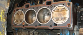
Now a few words about installing the cylinder head back onto the block. Firstly, be sure to replace the gasket, since it is installed only once. Of course, you must first clean the block and the surface of the head from traces of old gaskets. I did this using a special Dutch-made Ombra gasket remover, applying this liquid to the entire surface of the cylinder head:
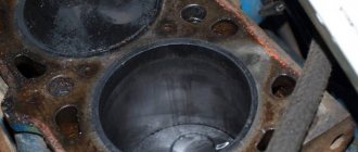
As a result, after about 10 minutes of waiting and careful work with a regular clothes brush, you get a fairly noticeable result. For comparison, I decided to do it as follows: I cleaned the first three combustion chambers with various means, from gasoline to WD-40, and the last one with this special tool.
Step-by-step removal and repair guide
- Removing the cylinder head is a critical step in our case. Before you begin removing and modifying the cylinder head, you need to drain all the antifreeze from the engine, and also remove the air filter along with the carburetor. Before doing this, disconnect all pipes and hoses of the system in advance. To carry out the work, you will need a standard set of tools, something that every driver should have, including wrenches, screwdrivers, and so on.
- When the carburetor is removed, it is necessary to begin dismantling the cylinder head cover, as well as aligning the marks on the crank pulley disk and the camshaft. In addition, the marks on the camshaft disc must match the mark on the housing. Read more about this in the video and photo.
- The next stage of dismantling will be to loosen the chain tensioner and remove the support washer. You need to sharply remove the screw and dismantle the cylinder head sprocket. You should also dismantle the VAZ 2106 camshaft along with the housing. Next, the rockers are removed, after which all high-voltage cables from the spark plugs are disconnected and the screws that secure the cylinder head itself are unscrewed. Next, the cylinder head is removed for repairs and first cleaned of deposits and carbon deposits.
Replacing the plug
New plug installed
- Replacing the plug can be a bit of a hassle, as you'll see in the video. Corrosion and deposits can make it difficult to remove. Use a hex wrench, but first spray the screw generously with VD-40. This does not always help, but it may be advisable in your case.
- If it was not possible to unscrew the plug in this way to replace it, you will have to drill it out. To do this, several holes should be drilled around the perimeter of the plug (drill through without fear, there is a thick wall under this plug, so you will not damage the unit). The main thing in this matter is not to damage the thread.
- The next step is to install the plug. There is nothing complicated about this issue. Before installing the plug, you will need to completely clean the threads of carbon and deposits; for this you can use a sharp object like an awl. Only after the threads have been cleaned can the plug be installed.
Replacing guide bushings
Installing bushings in the cylinder head
- Use pliers and a clamp to remove the bushings. When the elements are removed, measure their outer diameters; in practice, it is usually 0.05 mm less than the factory ones.
- To install failed bushings, you will need a hammer with a mandrel and motor fluid; you may need to heat the metal, for which you can use an electric stove.
- After the bushings are heated (if necessary), they are lubricated with oil to make them fit easier.
- When all eight bushings have been replaced with new ones, you need to wait some time until the cylinder head cools down. In this case, the inner diameter of the bushings must be turned so that the valves do not dangle inside, but at the same time they can move freely and do not jam.
Countersinking the head saddle
Scheme for seat countersinking
- As you can see from the video, replacing the cylinder head seat can cause some difficulties.
- You need to cut the metal layer in a circle, a detailed diagram is given above.
- After this, the cylinder head must be cut at an angle of 120 degrees until a round edge appears.
- Then you need to make a working chamfer up to 0.2 cm thick. This is done so that the valve rubs tightly.
How to tighten correctly?
You can tighten the bolts with the help of professionals or without the help of others. If you have never encountered the need to perform this task before, then below we will look at how to tighten the screws and in what sequence to do it. Observe the tightening torque precisely, as if the cylinder head bolts are overtightened, this will lead to cracks and damage to the cylinder head. If this happens, the car owner will have to do a complete repair of the unit. The working surface of the hole, as well as the threaded connection of the screw, must be very clean. A wire brush can be used to clean the cylinders. If during the task you find blind holes for the head screws, then carefully use lubricant for processing. If the volume of the substance is greater than required, it will be difficult to install the pin all the way.
It is recommended to lubricate the threads of new bolts with a small amount of engine oil or another type of lubricant.
Algorithm of actions
You need order and strength when you pull the cylinder head bolts:
Recommended tightening torque
Before you begin tightening, several conditions must be met:
You need to tighten the cylinder head fasteners of a VAZ-2106 car according to the following diagram:
You need to work in accordance with the diagram using a torque wrench. That is why it is so important to observe the tightening torque, as in the table:
| Circle number | Required tightening torque, kgf/m |
| 1 | 3,5-4,1 |
| 2 | 10,5-11,5 |
| 3 | only 11 screws are tightened with a torque of 3.5-4 |
How to properly tighten the cylinder head bolts on a VAZ 2106: cylinder head tightening torque
When is it necessary to puff?
First, let's look at the cases in which it is necessary to tighten the cylinder head bolts of a VAZ 2106 car engine:
The Ilyich Garage channel has published a video that will help you understand the process of tightening the cylinder head on a six.
Tools and materials
When purchasing bolts, it is recommended to give preference to branded parts. Be sure to look at the thread; it should be intact, without damage or flaws; if any, the fasteners are replaced.
Motor Repair Channel! And exciting! published a video that describes all aspects of the stretching process.
User Sergey Samarsky made a video where he carefully showed and outlined all aspects of the process of independently tightening the cylinder head screws of a VAZ car engine 2106.
Cracks
If overheated, the housing may also rupture in the form of cracks. They are not always visible to the eye, but their presence greatly affects the proper operation of the engine. If cracks have formed in the areas where the head and block meet, or in the valve seats, you will have no choice but to replace the block head with a new one. All other areas can be restored using argon welding. It is impossible to do such a cylinder head repair yourself due to the lack of specialized equipment - not all service stations have such welding.
As you can see, not everything can be repaired on your own. By correctly assessing the scope of work, you will nevertheless be able to save money on your budget.
Replacing the cylinder head gasket of a VAZ 2106
Replacing the cylinder head gasket of a VAZ classic on an engine with a chain drive is generally a fairly simple job; the main difficulty is aligning the crankshaft and camshaft marks during assembly. If the marks are set incorrectly, the engine will not work normally, or may not start at all.
You can change the cylinder head on a “Classic” without a pit or a lift; before performing work, you should prepare the necessary tools and a container for draining the coolant. From the tool you will need:
We replace the PGBC on engines 2101/03/06 as follows (on a carburetor engine):
After dismantling the head, we carefully protect the surfaces of the block and the cylinder head itself; there should be no irregularities on them. During assembly, all parts are installed in place, but there are some features:
How to remove the cylinder head without errors. Stages of work
And disconnect the tube, moving it slightly to the side:
It is also necessary to disconnect the plug from the temperature sensor, which is shown in the photo:
Everything is ready now. You can begin to unscrew the bolts securing the cylinder head to the engine block. For all this, we use a fairly powerful wrench with a head:
After the bolts have loosened, you can use a ratchet handle to perform this function a couple of times faster:
After all the bolts of the head are unscrewed, you can lift it by grasping the front part, or as it is more convenient for you:
↑ Camshaft
The camshaft is cast, cast iron, the same for all engine models. It rests on 5 journals and rotates in an aluminum bearing housing mounted on the cylinder head. A driven sprocket is attached to the front end of the camshaft. The camshaft is held against axial movements by a thrust flange placed in the groove of the front support journal of the shaft.
The camshaft is driven by a double-row roller chain from the crankshaft drive sprocket. The same chain drives the drive shaft of the auxiliary units. The chain drive has a semi-automatic tensioner with a shoe and a chain guide with plastic linings. A limit pin is installed at the bottom of the cylinder block to prevent the chain from falling into the crankcase when removing (on a car) the camshaft sprocket.
For the correct relative position of the stars, i.e. To set the valve timing, there are upper and lower timing marks. The upper marks are located on the camshaft sprocket and bearing housing, the lower marks are on the crankshaft sprocket and the camshaft drive cover.
↑ Valves
The valves are driven by a camshaft rotating in a bearing housing through intermediate levers. The gap between the camshaft cams and the lever is set with an adjusting bolt, on the spherical head of which the lever swings. The bolt is kept from loosening by a locknut.
The valves have two cylindrical springs - external and internal, sandwiched between a plate (top) and two support washers (bottom). The spring plate is held on the valve stem by two crackers, which when folded have the shape of a truncated cone. Each lever is pressed against the end of the valve with a special (hairpin) spring.
To increase the wear resistance of the rod, both valves are nitrided, and the ends of the rods on which the levers rest are hardened with high frequency current.
Installing the cylinder head
Now a few words about installing the cylinder head back onto the block. Firstly, be sure to change the gasket, because it is installed once. Obviously, you need to first clean the block and the surface of the head from traces of old gaskets. I did this using a special Dutch-made Ombra gasket remover, applying this liquid to the entire surface of the cylinder head:
As a result, after about 10 minutes of waiting and painstaking work with an ordinary clothes brush, you get a fairly tangible result. For comparison, I was going to do the following: I cleaned the first three combustion chambers with different means, from gasoline to WD-40, and the last one with this special tool. You can see the result clearly:
After all this is done, you can start installing the cylinder head back. In order to do this, you will need a special torque wrench, because these bolts need to be tightened with a certain torque in the following order:
It should also be noted that the following order must be observed:
We install all the removed parts in reverse order and completely assemble the VAZ 2106 engine. This is how you can remove the cylinder head yourself and install it back. I wish you success.
Damage to the cylinder head mating plane
To the formation of defects in the mating surface of the block head
The following reasons may be given:
Disadvantages of this kind are eliminated by processing the plane, with preparatory dismantling of the head.
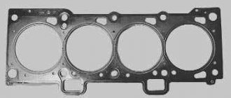
Cylinder head gasket
Head gasket
ensures a tight fit of the cylinder head to the cylinder block. The material for the production of the seal is reinforced asbestos, which is able to withstand the effects of high temperatures that arise during operation of the unit. In addition, reinforced asbestos can withstand high pressure under various engine loads.
Head milling
There are several cylinder head malfunctions that you cannot fix on your own. When the engine overheats systematically, the aluminum cylinder head becomes deformed. The perfectly flat surface of contact between the head and the engine block ceases to be so.
This leads to the gasket between the block and the head starting to leak. Replacing it with a new one does not solve the problem. In this case, grinding the adjacent surface may be the solution. Milling is performed on a special machine, which allows the work to be completed with perfect precision.
How to tighten the cylinder head of a VAZ 2107
This article will talk about how to replace the gasket and tighten the cylinder head of a VAZ 2107. In fact, it’s not difficult to do it yourself, although you’ll have to tinker a little. The head gasket is a small and cheap element, but it affects the operation of the entire internal combustion engine. And first, it’s worth finding out what symptoms of a damaged gasket may appear.
Basic faults
There is damage to the gasket in which the operation of the VAZ 2107 is strictly prohibited. But there are also breakdowns in which it is still possible to drive. So, here is a list of the main breakdowns:
And now you have decided that you really need to replace the gasket, your car has one or more symptoms. What to do? Arm yourself with keys and other tools, and then begin preparation.
Start of work
The very first step is to remove the air filter. Of course, on a carburetor engine it is somewhat easier to remove it. If you have an injector, you will have to tinker with its rubber fasteners. But the essence remains the same - it is necessary to disassemble the fuel system completely to get to the cylinder head. But we will look at the example of not an injection, but a carburetor seven. Still, there are many more classic cars with such a power system.
It is advisable to dismantle the carburetor, since if you remove the head along with it, you can accidentally damage it. On all classic series cars, the carburetor is removed in the same way. This procedure is quite simple, but it will take some time. Now you can unscrew the nut securing the distributor and remove the distributor along with the wires. Getting closer to the engine, all that’s left to do is drain the antifreeze from the system.
And then turn off all the pipes that you see. After this, it will be possible to dismantle the cylinder head cover. It is secured with nuts and shaped washers. Don't lose them during repairs. That's all, the preparation is complete, you can begin the most difficult part - dismantling and installing the cylinder head.
Replacing Valve Guides
Critical depletion of guide bushings occurs at a mileage of 150-200 thousand km. You can do the cylinder head repair by replacing the bushings yourself. To replace them you will have to dry out all the valves. Then, using a mandrel to knock out the bushings, remove them from the head body.
It will be a little more difficult to install the new bushings in place. For correct and easy installation, you should use a temperature imbalance - heat the block head (this expands the metal, and therefore the bushing seat), and cool the new bushings to a negative temperature. The head body in the right place should be heated to 100 degrees.
This can be done using an electric stove, placing the cylinder head on it so that the work site is in the zone of maximum heating. Having lubricated the new bushings (cooled in the freezer of a regular refrigerator) with machine oil, we drive them into the mounting sockets. If you follow the recommendations for temperature preparation described above, the bushings will fit in easily, like clockwork.
After the metal has cooled, the bushings must be expanded to a diameter that allows the valve to move without jamming or distortion. In this case, the work must be done so that the valve stem does not dangle. To perform this procedure, you need a special tool - a reamer. The peculiarity is that they need to work only on one side, turning the reamer to the end. A big mistake is to bore the guide bushing on both sides - you will end up having to change the bushing again.
Remember that cylinder head repair is a complex process, the slightest inaccuracy of which can result in wasted nerves and money. As a rule, an oversight makes itself felt after assembling and starting the engine. This does not always happen immediately, but certainly within the first thousand kilometers.
Cylinder head repair
If problems arise with the cylinder head of a Lada sixth model that requires removal of the unit from the car, then repair work can be carried out in a garage, having prepared the appropriate tools and components.
replacing valve guides
Broken spark plug
Quite rarely, but it happens that as a result of over-tightening the spark plug, a part breaks off on the thread in the spark plug hole. To remove the remains of the cylinder head spark plug element, you need to dismantle the threaded part and unscrew it using available tools.
Malfunctions when removal and installation of the cylinder head are required
There are a number of malfunctions due to which the cylinder head of the VAZ six has to be removed from the car for further diagnostics or repairs. Let's look at them in more detail.
Valve seat wear
Valve seats can wear out for several reasons:
The malfunction can be solved by straightening or replacing the saddles. In addition, the ignition system must be checked.
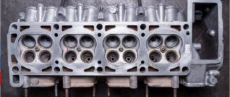
What does it consist of?
The cylinder head of the six is 8-valve and consists of the following structural parts:
The node in question is common to four cylinders. Cast iron seats and valve bushings are installed in the body. The working edges of the seats are processed after they are installed in the body to ensure a clear fit of the valves. The holes in the bushings are also processed after pressing into the cylinder head. This is necessary so that the diameter of the holes in relation to the working planes of the seats is accurate. The bushings have spiral grooves to lubricate the valve stem. On top of the bushings are valve seals, which are made of special rubber and a steel ring. The collars fit tightly onto the valve stem and prevent lubricant from entering the combustion chamber through the gaps between the bushing wall and the valve stem. Each valve is equipped with two cylindrical springs, which are supported by special washers. On top of the springs there is a plate that holds two crackers on the valve stem, shaped like a truncated cone.
Gasket burnt out
The following signs indicate that the cylinder head gasket has failed (burnt out or was punctured):
tightening the cylinder head on a classic. Replacing saddles
To replace the seat, it will need to be removed from the cylinder head. Since in garage conditions there is no special equipment for these purposes, welding or improvised tools are used for repairs. To dismantle the seat, the old valve is welded to it and then knocked out with a hammer. The new part is installed in the following sequence:
Removing the head
To remove the cylinder head you will need the following tool:
The sequence of actions for dismantling the unit is as follows:
↑ Cylinder head
The cylinder head is cast from aluminum alloy, has wedge-shaped combustion chambers, press-fitted seats and valve guides. Valve seats are made of special cast iron to provide high strength when exposed to shock loads. The working chamfers of the seats are processed after pressing into the cylinder head assembly to ensure precise alignment of the chamfers with the holes of the valve guides.
Valve guides are also made of cast iron and are pressed into the cylinder head with interference fit. There is a groove on the outer surface of the guide bushings into which a retaining ring is inserted. It ensures the accuracy of the position of the bushings when pressing them into the cylinder head and protects the bushings from possible falling out.
The holes in the bushings are processed after they are pressed into the block head. This ensures a narrow tolerance on the bore diameter and accuracy of its location in relation to the working chamfers of the seat and valve. The holes in the guide bushings have spiral grooves for lubrication. The intake valve bushings have grooves cut to half the length of the hole, and the exhaust valve bushings have grooves cut along the entire length of the hole.
Oil deflector caps made of heat and oil resistant rubber with a steel reinforcing ring are placed on top of the guide bushings. The caps surround the valve stem and serve to reduce the penetration of oil into the combustion chamber through the gaps between the guide sleeve and the stem.