Control over the operation of the vehicle, its components and assemblies is carried out by sensors. The devices transmit readings online to the electronic control unit for interpretation and response. If a discrepancy is detected by the latter, the “Check Engine” indicator appears on the dashboard. The driver makes a decision based on the data received.
List of sensors installed on Lada Vesta
- Controller (KSUD).
- Coolant temperature sensor (CTS).
- Knock sensor (DS).
- Parking sensor.
- Crankshaft position sensor (CPS).
- Camshaft position sensor (phase sensor).
- Absolute pressure sensor (ABP) and air temperature sensor (ATS).
- Parking sensor.
- Oxygen sensor (OS) or lambda probe.
- Fuel level sensor.
- Mass air flow sensor (MAF) or throttle valve.
- Vehicle speed sensor (VS).
- ABS sensor Lada Vesta.
- Oil pressure sensor.
- Shock sensor.
- Clutch and brake sensors.
How to check the knock sensor
The question of how to check the knock sensor (hereinafter DS) worries many car enthusiasts, in particular those who have encountered DS errors. There are actually two main testing methods - mechanical and using a multimeter. The choice of one method or another depends, among other things, on the type of sensor; they can be resonant or broadband. Accordingly, their verification algorithm will be different. For sensors, the value of changing resistance or voltage is measured using a multimeter. An additional check with an oscilloscope is also possible, allowing you to look in detail at the process of triggering the sensor.
KSUD
KSUD - engine control system controller (catalog number 21127141102062). This is the main sensor that receives data about the state of the technical equipment from the systems.
Installed in the engine compartment, on the left in the direction of travel of the car. Built into a plastic case along with power fuses.
Signs of inoperability:
- no data on the display when starting the engine;
- partial display of data;
- sound accompaniment during work.
The service life is unlimited according to the instruction manual. In practice, no more than 5 years, after which it needs to be replaced with a new one.
How to troubleshoot
All that matters to us is the ill-fated pipe in question.
The order of my actions (step by step instructions):
- I removed the wallpaper from the ends of the tube.
- I measured the diameter of the inlet pipe with a caliper: it turned out to be 8 mm.
Kits are sold by different manufacturers, and the sizes of sealing rubber bands may vary. Therefore, if you use a ring that is too thick, you may break the plastic fitting. The place where the latch is attached may also break off. I am not imposing this procedure on anyone, use the advice at your own responsibility. But it helped me solve the problem.
I tried to put the elastic band on the pipe - it stood up like a native one! Maybe AvtoVAZ forgot to install them. Of course, they are not oil resistant, but in this case this will not matter. I put the fitting on top and it was a little loose. I put on the second ring - also rather weak. Then he put on the third one.
After that I put the fitting on tightly, it turned out very tight. From the other end of the tube I performed similar procedures. Now nothing is loose. I installed a decorative engine cover.
DTOZH
Coolant temperature sensor (article 2190-1306010). Controls the temperature in the vehicle's cooling system. When a critical point is reached, it signals on the dashboard to notify the driver.
Related link:
Eliminating fogging of headlights on Lada Vesta
Installed in the thermostat cover housing. Service life – 75-85 thousand km. Cannot be repaired.
Signs of inoperability:
- incorrect display of operating temperature;
- display inactive;
- unstable degree display.
Absolute pressure and air temperature sensor
DBP and DTV are designed to determine the pressure in the intake receiver and its temperature. Directly participates in the formation of the fuel mixture by measuring air parameters and transmitting them to the controller.
LADA VESTA. AIR PRESSURE AND TEMPERATURE SENSOR (DDTV) OF ENGINE 21129 WITH M86 EURO-5 CONTROLLER
The air pressure and temperature sensor (APTS) is installed on the intake module (Fig. 1.1-02). The DDTV includes an absolute pressure sensor in the intake manifold (MAP) and an intake air temperature sensor (IAT).
Rice. 1.1-02. Location of DDTV in the engine compartment of cars of the LADA VESTA family: 1 - DDTV
The output signal of the DBP connected to the controller is a DC voltage in the range of 0.15. 4.6 V, the value of which depends on the pressure in the intake manifold. Using this signal, the controller calculates the amount of air sucked into the intake manifold per cycle.
If a malfunction occurs in the DBP circuit, the controller stores its code in its memory and turns on the alarm. In this case, the controller calculates the amount of intake air based on the crankshaft speed and throttle position.
The sensitive element of the DTV is a thermistor (a resistor that changes resistance depending on temperature, see Table 1.1-01). The output signal of the DTV connected to the controller is a DC voltage in the range of 0.3. 4.9 V, the value of which depends on the temperature of the air passing through the sensor.
If a malfunction occurs in the DTV circuit, the controller stores its code in its memory and turns on the alarm. In this case, the controller replaces the sensor readings with a fixed air temperature value (32 °C).
Table 1.1-01
Table of dependence of DTV resistance on intake air temperature
Resistance,
Resistance,
LADA VESTA. ENGINE THROTTLE POSITION SENSORS 21129 WITH M86 EURO-5 CONTROLLER
In a system with an EDP, two TPS are used. TPS are part of the throttle pipe with electric drive.
The TPS is a potentiometric type resistor, one of the terminals of which is supplied with a reference voltage (5 V) from the controller, and the second is supplied with ground from the controller. From the pin connected to the moving contact of the potentiometer, the TPS output signal is supplied to the controller.
The controller controls the throttle position electrically in accordance with the position of the accelerator pedal. Based on the TPS readings, the controller monitors the position of the throttle valve.
When the ignition is turned on, the controller sets the damper to the pre-start position, the degree of opening of which depends on the coolant temperature. In the pre-start position of the throttle valve, the output signal of TPS 1 should be within 0.58. 0.70 V, output signal TPS 2 within 4.30. 4.42 V.
If you do not start the engine within 15 seconds and do not press the accelerator pedal, the controller de-energizes the electric drive of the throttle pipe and the throttle valve is set to the 6-7% throttle opening position. In the de-energized state (LIMP HOME) of the electric throttle valve drive, the output signal of TPS 1 is within 0.70. 0.75 V, output signal TPS 2 within 4.25. 4.30 V. Then, if no action is taken within 15 seconds, the checking (“learning”) mode of the 0-position throttle valve will begin - complete closing and opening of the throttle valve to the pre-start position and then the electric throttle valve drive will again switch to de-energized mode.
At any throttle position, the sum of the TPS 1 and TPS 2 signals should be equal to (5±0.1) V.
If a malfunction occurs in the TPS circuits, the controller de-energizes the electric throttle drive, stores its code in its memory and turns on the warning light. In this case, the throttle valve is set to the 6-7% throttle opening position.
LADA VESTA. ELECTRONIC ACCELERATOR PEDAL (EPA) OF ENGINE 21129 WITH M86 EURO-5 CONTROLLER
On vehicles with EDP, an electronic accelerator pedal (EAP) is used, which electrically transmits a signal about the position of the accelerator pedal to the controller. The EPA is located on a bracket under the driver’s right foot.
The EPA uses two accelerator pedal position sensors (APPS). DPPAs are potentiometric-type resistors that are supplied with 5 V power from the controller. DPPA are mechanically connected to the drive from the pedal lever. Two independent springs between the pedal lever and the housing create a return force. Receiving an analog electrical signal from the electronic control unit, the controller generates a signal to control the throttle position.
The output voltage of the DPPA changes in proportion to the pressing of the accelerator pedal. When the accelerator pedal is released, the DPPA 1 signal should be within 0.50-0.85 V, the DPPA 2 signal should be within 0.25-0.43 V. With the accelerator pedal fully depressed, the DPPA 1 signal should be within 4.19-4.59 V, the signal DPPA 2 within 2.095.2.295 V. At any position of the accelerator pedal, the DPPA 1 signal should be twice as large as the DPPA 2 signal.
Rice. 1.1-03. Location of the electronic accelerator pedal in the interior of cars of the LADA VESTA family: 1 - electronic accelerator pedal
LADA VESTA. COOLANT TEMPERATURE SENSOR (DTOZH) OF ENGINE 21129 WITH CONTROLLER M86 EURO-5
The sensor is installed in the engine coolant flow on the thermostat, on the cylinder head (Fig. 1.1-04).
Rice. 1.1-04. Location of the coolant temperature sensor in the engine compartment of cars of the LADA VESTA family: 1 - coolant temperature sensor
The sensitive element of the coolant temperature sensor is a thermistor, i.e. a resistor whose electrical resistance changes depending on the temperature. High temperature causes low resistance, and low coolant temperature causes high resistance (see Table 1.1-02). The controller supplies a voltage of 5 V to the coolant temperature sensor circuit.
The controller calculates the coolant temperature based on the voltage drop across the DTOZH. The voltage drop is relatively high when the engine is cold and low when the engine is warm. Coolant temperature is used in most engine management functions.
If a malfunction occurs in the DTOZh circuits, the controller enters its code into its memory, turns on the warning light and the cooling system fan, and calculates the coolant temperature using a special algorithm.
Table 1.1-02
Table of dependence of DTOZ resistance on coolant temperature (±2%)
Control over the operation of the vehicle, its components and assemblies is carried out by sensors. The devices transmit readings online to the electronic control unit for interpretation and response. If a discrepancy is detected by the latter, the “Check Engine” indicator appears on the dashboard. The driver makes a decision based on the data received.
DD
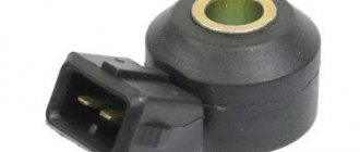
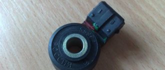
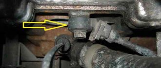
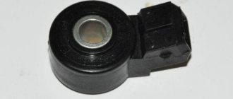
Knock sensor (part number 2346015900). Designed to record high-frequency vibrations of the cylinder block that occur during fuel combustion.
Located on the outer wall of the cylinder block. The service life is unlimited. Cannot be repaired.
Signs of inoperability:
- difficulty starting the engine;
- Unstable engine operation at idle speed.
DPKV
Crankshaft position sensor (article 8200701972-B). Online, the ECU sends data on crankshaft speed and tilt angle.
Installed in the tide hole of the oil pump cover. Resource – 80-90 thousand km. Cannot be repaired.
Signs of inoperability:
- the engine does not start for a long time.
Phase sensor
Camshaft position sensor (part number A2C90920400). Informs the electronic engine control unit when the piston reaches top and bottom dead centers during the compression stroke.
Installed on the engine, below the valve covers. Resource – 90-100 thousand km. Cannot be repaired.
Signs of inoperability:
- The ECU goes into emergency mode;
- The engine is unstable at idle speed.
Checking the knock sensor with an oscilloscope
There is another method for checking DD - using an oscilloscope. In this case, it is unlikely that it will be possible to check the functionality without dismantling it, since usually an oscilloscope is a stationary device and it does not always make sense to carry it to the garage. On the contrary, removing the knock sensor from the engine is not very difficult and takes a few minutes.
The check in this case is similar to those described above. To do this, you need to connect two oscilloscope probes to the corresponding terminals of the sensor (it is more convenient to check a broadband, two-terminal sensor). Next, after selecting the operating mode of the oscilloscope, you can use it to look at the amplitude shape of the signal emanating from the sensor being diagnosed. In quiet mode it will be a straight line. But if mechanical shocks are applied to the sensor (not very strong, so as not to damage it), then instead of a straight line, the device will show splashes. And the stronger the blow, the greater the amplitude.
Naturally, if the amplitude of the signal does not change during the striking process, it means that the sensor is most likely faulty. However, it is better to diagnose it further by measuring the output voltage and resistance. Also remember that the amplitude surge should be short-lived, after which the amplitude is reduced to zero (there will be a straight line on the oscilloscope screen).
You need to pay attention to the shape of the signal from the sensor
However, even if the knock sensor worked and produced some kind of signal, its shape must be carefully examined on an oscilloscope. Ideally, it should be in the shape of a thick needle with one sharp, pronounced end, and the front (sides) of the splash should be smooth, without jagged edges. If the picture is like this, then the sensor is in perfect order. If the pulse has several peaks, and its front has jagged edges, then it is better to replace such a sensor. The fact is that, most likely, the piezoelectric element in it is already very old and it produces an incorrect signal. After all, this sensitive part of the sensor gradually fails over time and under the influence of vibration and high temperatures.
Thus, diagnostics of a knock sensor with an oscilloscope is the most reliable and complete, giving the most detailed picture of the technical condition of the device.
DBP and DTV
Absolute pressure sensor and air temperature sensor (article 21150382821003). Informs the ECU about the amount of air consumed in order to adjust the enrichment of the combustible mixture in the combustion chamber.
Installed on the air pipe manifold. Resource – 90-100 thousand km. Cannot be repaired.
Signs of inoperability:
- the engine is unstable at idle speed;
- passive acceleration dynamics.
Lambda probe
Oxygen concentration sensor (part number 226A41771RF). Separates the gas flow in the exhaust manifold and informs the ECU about the gas concentration.
Installed on the outer wall of the exhaust manifold. Resource over 100,000 km. Cannot be repaired. Signs of inoperability:
- error indication on the dashboard.
Mass air flow sensor
Mass air flow sensor (article 8450020039). Installed behind the air filter housing. Reads the amount of air consumed by the engine while driving.
Related link:
Do-it-yourself seat heating repair on Lada Vesta
Resource over 100,000 km. Cannot be repaired.
Signs of inoperability:
- error indication on the dashboard.
DS
Vehicle speed sensor (article 8450006894). Measures the actual speed of movement and transmits data to the electronic engine control unit.
Installed at the top, on the clutch housing cover. Resource over 100,000 km. Cannot be repaired. Signs of inoperability:
- no speedometer readings.
DDM
Oil pressure sensor (article 8200671275). Installed behind the cylinder head. When the minimum level is reached, the contacts close and an error signal is transmitted to the dashboard.
Resource over 100,000 km. Cannot be repaired. Signs of inoperability:
- error alarm on the car dashboard.
Motor Controller
The controller is responsible for all processes necessary for the operation of the engine and is the main device in the car. Without this block, the operation of the car engine will be impossible, as well as if it breaks down.
Signs of malfunction:
Failure of the unit will lead to a complete stop of the engine and will not allow the internal functions of the car to operate.
Review of Manufacturer Prices
| Name | Price in rubles |
| Controller (KSUD) | From 1200 |
| Coolant temperature sensor (DTOZH) | From 450 |
| Knock sensor (DS) | From 450 |
| Crankshaft position sensor (CPS) | From 450 |
| Camshaft position sensor (phase sensor) | From 650 |
| Absolute pressure sensor (ABP) and air temperature sensor (ATS) | From 500 |
| Oxygen sensor (absorber) | From 350 |
| Mass air flow sensor (MAF) | From 350 |
| Vehicle speed sensor (VS) | From 350 |
| Oil pressure sensor | From 350 |
| Clutch and brake sensors | From 350 |
| *prices are as of April 15, 2019 | |
Conclusion
Use the specified list of sensor part numbers when purchasing spare parts or new components. Despite the simplicity of the design, install the equipment in certified workshops, where they provide a quality guarantee for the work performed. If any difficulties arise, please contact the managers of the official representative offices of the car brand for advice.
Resistance measurement
Knock sensors, both resonant and broadband, can be checked by measuring changes in internal resistance in dynamic mode, that is, during their operation. The measurement procedure and conditions are completely similar to the voltage measurement described above.
The only difference is that the multimeter is turned on not in the voltage measurement mode, but in the mode for measuring the electrical resistance value. Measuring range: up to approximately 1000 ohms (1 kohm). In a quiet (non-detonation) state, the electrical resistance value will be approximately 400...500 Ohms (the exact value will differ for all sensors, even those of the same model). Measuring broadband sensors should be done by connecting the multimeter probes to the sensor terminals. Next, knock either on the sensor itself or in close proximity to it (at the place where it is mounted in the engine, or, if it is dismantled, then place it on a metal surface and hit it). At the same time, carefully monitor the tester readings. At the moment of knocking, the resistance value will briefly increase and return back. Typically the resistance increases to 1...2 kOhm.
As in the case of measuring voltage, it is necessary to ensure that the resistance value returns to its original value and does not freeze. If this does not happen and the resistance remains high, then the knock sensor is faulty and should be replaced.
As for old resonant knock sensors, their resistance is measured in a similar way. One probe must be connected to the output terminal, and the other to the input mount. It is imperative to ensure quality contact! Next, using a wrench or a small hammer, you need to lightly hit the sensor body (its “barrel”) and at the same time look at the tester readings. They should increase and return to their original values.
It is worth noting that some auto mechanics consider measuring the resistance value to be a higher priority than measuring the voltage value when diagnosing a knock sensor. As mentioned above, the voltage change during sensor operation is very small and amounts to literally a few millivolts, while the change in resistance value is measured in whole Ohms. Accordingly, not every multimeter is able to detect such a small voltage drop, but almost every one can detect a change in resistance. But, by and large, this does not matter and you can run the two tests sequentially.
Reviews
| № | Positive |
| 1. | Dmitrievich (drive2.ru): in three years of operation of the car, I have never changed the sensors. |
| 2. | Semyon (prom.ua): at a mileage of 65,000 km, I replaced the mass air flow sensor, I have already driven 100,000 km, there are no problems. |
| 3. | Sergey (drom.ru): 80,000 km on the speedometer, replaced the temperature sensor, no complaints about the quality of the car. |
| 4. | Konstantin (rozetka.ua): I recently replaced the DDT, bought the original one, the price was 350 rubles. I installed an additional alarm and shock sensor. |
| 5. | Vladimir (Auto.ru): I’m happy with the car, there are no special comments, the equipment is working normally. |
| 6. | Nikolay (Auto.Mail.ru): in two and a half years of using the equipment, I replaced the oil pressure sensor once. The car is under warranty, the dealer service is free. |
| 7. | Kirill (drive2.ru): The ABS sensor failed at 90,000 km, replaced it with a new one. I bought it at the company store. |
| 8. | Sergey (drive2.ru): I can’t say anything special about the sensors, they work in normal mode. |
| Negative | |
| 9. | Vladimirovich (prom.ua): I additionally installed a parking sensor, I missed it so much in the “Standard” configuration. Also replaced the idle speed sensor. |
| 10. | Alexander (Bibika.ru): the temperature sensor often fails; I don’t know what causes this. |
| 11. | Valentin (drive2.ru): the speedometer does not display information correctly on the dashboard, the dealer recommended replacing it under warranty. |
| 12. | Semyon (Avtodispatcher.ru): I installed the tire pressure sensor myself; it is not supplied as standard. |
Related link:
Armrests for Lada Vesta: review, modifications, characteristics, installation recommendations
Lada Vesta 1.8 21179 Detonation on any fuel
Welcome to ChipTuner Forum.
Theme Options
0.3-0.4V, when the gas is released it drops to 0.2, under load it increases to 0.6. Not really hoping for results, I recently changed my DD to Kaluga, with the AT index. And there is a result. At XX voltage on DD
1.5V, when releasing the gas it drops slightly to 1.3-1.4V, under load on average 1.7-1.8V with peaks above 2V. At the same time, at low speeds, detonation is now not audible at all, in any way. Victory? On the one hand, yes, but... the car stopped moving. I'm looking at what's happening there now. And the following happens. With uniform movement, everything is fine, the rebounds on the cylinders are 0, but if you accelerate even a little or even a small slide will appear - a rebound of 6-9-12 degrees. In the gas to the floor mode, it always hangs at a maximum of 12 degrees across all cylinders. In some modes, the real SOP is established generally after TDC (
2000 rpm). In the region of 3-4 thousand, ringing is also heard - there is not enough angle adjustment range. Below are my thoughts on further search for a solution to the problem: What causes detonation in general: 1. Bad fuel? In a city with over a million people, all network gas stations have donkey gasoline instead of 95. It could be, of course, but other cars somehow drive on this, so it seems unlikely. 2. Raised corners of the UZ in the firmware? The rebound makes the angles not at all early, but in some modes there is still a ringing sound, that is, it seems that the adjustment of the OZ is working adequately, or not? 3. Is there soot in the KS as thick as a finger? Of course, I didn’t climb into the cylinders with an endoscope, but for the last 1.5 years I have been using gasoline with detergent additives, and periodically I add Techron to the tank again to clean the CS. The option is possible, but seems unlikely. 4. Lean mixture? So the ECU would see this through the lambda. Its graph looks quite lively, and even in power modes (when lambda regulation is disabled) the situation should have improved, but no, detonation still occurs. How else can you check for a lean mixture? 5. ? In general, I have run out of options and, to be honest, I am at a dead end, so I will be happy to listen to your thoughts. I apologize for such an unreadable sheet, I wanted to describe the situation in as much detail as possible.
Source
