In the VAZ 2114, as in all cars, special automobile oil is used to lubricate the rubbing parts of the engine and cool them. It helps to extend the life of the engine, the oil circulates through the engine under a certain pressure, which is pumped by a special pump; if there were no pressure in the system, the rubbing parts would cease to be lubricated, which would lead to rapid engine breakdown. This problem occurs quite often, and to inform the driver about a decrease in oil pressure in the engine lubrication system, a special VAZ 2114 oil pressure sensor is used. It is about this sensor that our article today is about; the article describes the principle of operation of the sensor, its design, as well as methods of replacement .
Purpose and design of DDM
The main purpose of this sensor is to measure the pressure in the engine lubrication system and inform the driver that the pressure has dropped to critical values or is absent altogether.
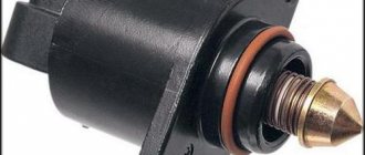
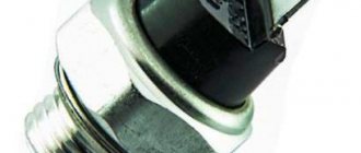
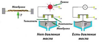
The sensor itself does not have a complex structure and only has a valve, which, in the presence of pressure, opens the electrical contact, thereby turning off the power circuit for the oil pressure warning lamp.
When the pressure decreases or is completely absent, the lamp lights up and informs about malfunctions in the engine. The operation of the sensor can be observed with the engine stopped and the ignition on; when starting, the lamp should go out, which means that the sensor is working properly and the engine lubrication system has the necessary pressure to lubricate all parts of the internal combustion engine.
Importance of the device when operating a car
The data transmitted by the device to the on-board panel is important information.
They indicate possible malfunctions in the operation of the machine:
- the oil level drops below the minimum value;
- clogged oil filter;
- violation of the controller wires;
- the appearance of sediment in the oil pan;
- malfunction of the oil supply pump;
- engine oil leakage.
The indicator can also indicate a malfunction of the oil pressure device itself, unlike other breakdowns - this one is minor.
Sensor check
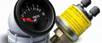
The sensor can only be checked by measuring the oil pressure in the engine using a special pressure gauge. To do this, the suspicious sensor is unscrewed and a fitting is screwed in its place, to which a pressure gauge is connected and the internal combustion engine is started.
The normal oil pressure at XX of a warm VAZ 2114 engine should be at least 2 bar. At speeds above 3000 rpm the pressure should be 4-5 bar.
If the oil pressure is much lower than the permissible parameters, it is necessary to repair the engine, but if the oil pressure is normal, then most likely the sensor is faulty and requires replacement.
How to check the serviceability of a part
After starting the internal combustion engine, the oil pump pumps fluid to all engine systems. From the crankcase through the filter, oil is supplied to each part, and the pressure gradually rises to operating condition. The light on the instrument panel lights up when there is insufficient pressure in the system. If the indicator does not go out longer than usual, then it is worth checking whether the sensor is working properly.
But a long-burning light can also indicate problems with low pressure due to other parts:
- The oil filter is clogged with dirt. The liquid entering the system is insufficient. The pump cannot create the required pressure. In this case, it is worth cleaning the filter and replacing it with a new one.
- Carbon deposits, which are washed away by oil from inside the engine, can also accumulate on the oil pan, clogging the oil receiver mesh and reducing its permeability. It is better to drain the lubricating fluid from the crankcase. If contamination is severe, replace with new oil.
- Oil pump malfunction.
- High wear of engine parts, in particular the crankshaft.
- Poor quality oil is poured - it is worth buying proven brands recommended by the car manufacturer (semi-synthetic 10W-40, volume - 3.5 l).
- Insufficient fluid level in the system - checked when the engine is cold with a dipstick, solved by adding oil.
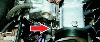
If these reasons are considered, and the lamp on the panel is on, then the problem is a malfunction of the DADM (emergency oil pressure sensor) or the wiring from the device to the indicator. To check the device, you need to know where the faulty oil pressure sensor is located on the VAZ 2114. The part is located under the decorative cover of the internal combustion engine (internal combustion engine) on the left side of the engine compartment. The device is installed near the timing belt (gas distribution mechanism), on the right in the cylinder head (cylinder head), below the valve cover.
To professionally check the performance of the emergency oil pressure sensor, it is recommended to take the car to a specialized service station. But this is not always possible. Therefore, you need to know how to check the oil pressure sensor yourself. There are several options here:
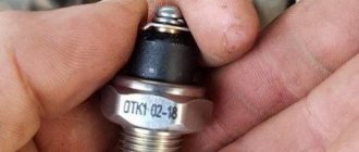
- Visual inspection of the part - smudges in the place where the device is fixed may indicate a problem with the sealing washer. It is necessary to replace the ring and wipe the installation site. The fastener also leaks in the event of a malfunction of the excess pressure relief valve in the oil pump (the pressure in the system is above 0.8 atmospheres). If signs of a leak are found at the terminal attachment point, this clearly indicates the need to replace the sensor itself.
- The sensor is unscrewed and a pressure gauge is installed in its place. It is necessary to start the car engine and monitor the readings at idle speed. At normal oil pressure in the system, the parameter will be within 0.65 atmospheres. This indicates a faulty part.
- Without starting the internal combustion engine, with the sensor removed, it is necessary to crank the starter. Splashes from the device mounting hole indicate the presence of pressure in the system. But in this way it is impossible to find out its parameters.
- A new sensor is installed in place of the old device. If it works correctly, then the old device is faulty.
Why is oil leaking from under the sensor?
The sensor is in direct contact with the oil, and when the sensor ages, its sealing ring, which is installed between the sensor and the cylinder head housing, becomes dented and begins to leak oil, which leads to fogging around the sensor or even to excessive oil leakage from under the sensor.
It is also quite common to see oil leaking through the sensor connector. For both reasons, it is recommended to replace the sensor with a new one.
Features of diagnostics
Before carrying out diagnostics, it is recommended to conduct a visual inspection of the device for damage to the controller housing, stains from fluid leaking from the motor and other changes. If oil traces are detected, you need to make sure that the malfunction is in the sensor; inspecting the power unit will help make sure of this. When consumables leak from the regulator, the cause of the problem is related to wear on the seal. And if oil dripping occurs from the terminal connectors, you cannot do without replacing the controller.
To more accurately determine malfunctions during the operation of the device, diagnostics using a voltmeter will help:
To do this, you will need a pit or overpass and follow the following instructions:
- unscrew the bolts securing the protective coating of the unit;
- dismantle the protection;
- if DDM is detected, start the engine;
- disconnect the power cord from the device;
- use a tester to diagnose the voltage (voltage norm is 12 volts).
If the voltage is low, the cause of the malfunction is the display unit or the contacts of the electrical circuit, as well as its break.
Replacement
Replacement is quite simple, you just need to prepare a 21 mm wrench and you can start replacing.
- Remove the connector from the sensor and unscrew it using a key.
- There is no need to be afraid that the oil will leak; this will not happen, since the engine is without pressure.
- We install the new sensor in the reverse order, having first cleaned the seat from dirt.
Photo gallery
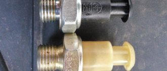
1. Schematic principle of operation of the DDM on Chetyrka
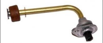
2. DDM with a dial indicator for displaying into the car interior
3. Scheme of operation of the device on Chetyrka
Loading...
Engine control circuit for VAZ 2111 (January 5.1, Bosch M1.5.4N)
- Fragment of the mounting block;
- Electric engine cooling fan;
- Automotive anti-theft system status indicator;
- Automotive anti-theft system control unit;
- Coolant temperature sensor;
- Air flow sensor;
- Throttle pipe;
- Block connected to the throttle position sensor;
- Block attached to the idle speed control;
- Controller;
- A block connected to the air conditioner wiring harness;
- Oxygen sensor;
- Knock sensor;
- Crankshaft position sensor;
- Speed sensor;
- Adsorber;
- Accumulator battery;
- Main relay;
- A block connected to the anti-lock brake system wiring harness;
- Diagnostic block;
- Main relay circuit protection fuse;
- Controller protection fuse;
- Fuse for protecting the electric fuel pump and its relay;
- Relay for turning on the electric fuel pump;
- Electric fan switch relay;
- A block connected to the instrument panel wiring harness;
- A block connected to the instrument panel wiring harness;
- Ignition module;
- Electric fuel pump with fuel level sensor;
- Spark plug;
- Injectors;
F — Front harness wire going to the “B+” terminal of the generator; G - Front wiring harness wires.
The order of conditional numbering of plugs in blocks:
A - Controller; B — Control unit of the automobile anti-theft system; B — Indicator of the status of the automobile anti-theft system; G - Pads 26; D - Throttle pipe; E - Air flow sensor; F - Electric fuel pump and oxygen sensor; 3 — Speed sensor; And - Ignition module.
Purpose of plugs in block 26:
- To the low-voltage tachometer input in the instrument cluster;
- —
- To the engine management system control lamp in the instrument cluster (from the controller);
- To the dome light switch located on the driver's door pillar;
- To the engine control system control lamp in the instrument cluster (+ power supply);
- To the trip computer (fuel consumption signal);
- To the instrument cluster (vehicle speed signal);
- To terminal “15” of the ignition switch (plug 4 of the switch block)