A useful addition to the design of any vehicle is a central lock, which simultaneously with opening the driver's door allows you to control all the doors of the car. Unfortunately, the VAZ-2114 central lock sometimes begins to function incorrectly, this manifests itself in a lack of response when turning the key in the lock or when pressing the control key on the remote control. Let's consider the main reasons causing the malfunction of this unit.
Central locking diagram for VAZ 2114
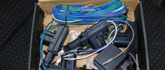
The system consists of the following components:
- mounting block;
- 8 amp fuse;
- 4 gearmotors (one in each door, and the one in the driver's door has a contact group);
- central locking control unit;
- wires (red, black, blue, yellow) and plugs;
- rods that are located in each door;
- limit switches that signal the current state of the door (open or closed).
Instructions for disabling immo
If your car is equipped with an alarm or central locking, then you don’t have to worry about the safety of the car when the immo is turned off.
If you do not know how to turn off the alarm, then this procedure is carried out using the service button, which is usually called Valet. The shutdown procedure is described in more detail in the service manual. We will not describe it, since it is individual for each individual car model. As for immobilizers, they are disabled according to the following principle:
- First you need to disconnect the control unit connector.
- Next, you need to dismantle the control unit; to do this, unscrew the side covers in the so-called doors on the console using a screwdriver, then disconnect the terminals and remove the device.
- Now you need to read the EPROM. EPROM is non-volatile memory; it is needed because it contains data on the operation of the anti-theft device. After completing the work, the EPROM is installed in place.
- After this, you need to disconnect the PAK loader from the control module.
- Disconnect the module so that the device is not automatically blocked during installation.
- Next, we proceed to dismantling the immobilizer itself. As mentioned above, it is located behind the center console, in the area of the steering wheel. The block is located at the audio system level.
- You need to feel and disconnect the plug with your hand; there are 20 contacts on it. Having done this, you can begin to restore the K-Line, for this you will need to close the contacts on the connector, in particular, we are talking about outputs 9 and 18. That is, they must first be cut and then insulated. Having done this, reinstall the block and try to start the engine. If you did everything correctly, the engine will start.
Where is the central locking of the VAZ 2114
The central locking system is located in the driver's door, just like the electric drive. If we talk about the system as a whole, it is distributed over 4 doors (in some cases it also extends to the trunk), and the central panel (control unit).
Testing and diagnostics
conclusions
In this article, we touched upon only some of the most common problems associated with the operation, repair and maintenance of a centralized lock. Despite the fact that the node has plenty of problems, restoring its functionality is not a difficult, much less an impossible task. Usually, to achieve smooth, efficient operation of the system, only practical skills are missing. After receiving them, you will be able to repair any complexity! If you want to install the central locking on a VAZ 2114 yourself, then here is a video instruction:
Bottom line
In this simple way, we installed the Chinese central locking control unit without cutting a single factory wire or drilling a single extra hole in the body.
PS - in 3 months of operation nothing burned, melted or exploded. The control unit does not discharge the battery, since it is not an alarm and it does not have a constant connection with the key fob; the only source of consumption is the light bulb. The BU key is triggered when it is relatively close to the car; the CU's antenna is not large and picks up the signal in different places at a distance of 5 to 20 meters.
Issue price:
- — BU: 900 rubles
- — Actuator: 390 rubles
- — Door rod repair kit: 108 rubles (2 sets)
- — Door rod bushing: 40 rubles (2 pcs.)
Central locking diagram for VAZ 2114
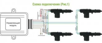
To connect a car alarm to the central locking on a VAZ 2114, you need to know the circuit diagram of the central locking system itself. This will allow you to understand what should be connected to what. Below is a standard lock diagram.
The control module is located under the vehicle's dashboard on the left side. There are six wires in its connector. If the white wire is connected to terminal 7, then it is responsible for unlocking the doors. But in some vehicles, terminals 5 and 7 may not be used. In this case, this function is performed by the brown wire connected to terminal 8. Terminals 5 and 6 are always responsible for locking. When planning to install the alarm, you need to make sure that the driver’s door contains exactly the 5-wire actuator, typical for this VAZ model. Some cars may have a toggle switch instead. In this case, you will need to install an actuator.
Central locking actuator
It is difficult to do this with your own hands without knowledge of auto electrics. Therefore, if they are absent, it is better to contact a car service.
Introduction
I went online to search for information on how people connect these Chinese units to a VAZ and came to the conclusion that everyone installs such units in a terribly artisanal way, removing half of the wiring, adding some of their own, and in the end, all this does not “successfully” work. Among the makeshift connection instructions, I came across the only normal article by Soliderus, who installed a similar control unit on his Chrysler; his article helped me a lot. But since we have a harsh domestic auto industry, we had to invent our own connection diagram, but first things first.
Please read this entire article first before disassembling the machine; you may not have any parts on hand or may be missing some of the original wiring.
Alarm connection points for VAZ 2114
Most modern alarms can be connected to the door, hood and trunk switches.
Therefore, in order to connect the signaling system to the VAZ 2114, you need to observe the following points:
- Connector X3 with a blue-red wire to the car door sensors;
- X9 – to a two-level shock sensor, which is attached to a metal surface;
- X8 and X7 – usually not used;
- X6 – to the Valet service button, which is placed in a place hidden from prying eyes in the car;
- X5 – LED alarm indicator, which is located on the dashboard;
- X4 – to the transmitting sensor receiving module. It is installed on the windshield in one of the upper corners;
- X3 – connector with a large number of wires.
To connect the car alarm to all car systems, you need to connect the wires in this order:
- Red – to the “plus” of the ignition switch;
- Black/green and green/yellow – to direction indicators and sidelights;
- Black – for vehicle weight;
- Yellow – to the ignition switch;
- Gray – positive emergency siren;
- Blue/red – “plus” door entrance;
- Black/red – additional blocking relay;
- Orange/gray – to the hood opening sensor;
- Orange/white – trunk opening sensor;
- Orange/purple – to the brakes, according to the diagram presented in the instructions for the security device. It may differ for signaling devices from different companies;
- X2 – to door opening activators;
- X1 – to the ignition switch. It should be connected to the red wire.
Repair features
If the central locking of the VAZ 2114 has stopped working, then you need to conduct diagnostics and find the cause of the breakdown (the author of the video is Nikolay Bogdanov).
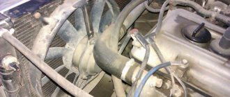
Then carry out the appropriate repairs. Problems with central locking on the VAZ 2114 most often arise at low temperatures and high humidity. The reason is the locks with solenoids that are installed from the factory. It is better to replace them with locks with an electric motor.
If the drive is not working on only one door, it is necessary to check its electrical circuit for an open circuit by testing it. Most often, broken wires are located in the corrugation. Since the doors are opened and closed frequently, the insulation cannot withstand the load. The break is restored by replacing the wire and connecting the broken sections using female-male terminals.
Connecting to wires
- 2-3 pieces of 1N4001 diodes for a current of no more than one Ampere;
- One 1N5401 3 Ampere diode;
- Also, some security systems may require two 4-5 Ampere power diodes.
To connect the device to the central locking system, you need to find two wire harnesses on the floor next to the driver's door. To get them, you need to remove the sill trim and side panel. The first harness contains the door switch cable. A 1N5401 diode must be installed in its gap.
In the second harness you need to find the wire going to the handbrake, into which you should insert the second 1N4001 diode.
The blue cords of both harnesses must be connected to the car alarm.
Correct exit procedure, example
Did you like the article? Follow our channel for new ideas of useful car tips. Subscribe to us in Yandex.Zen. Subscribe.
The problem of how to connect an alarm system to the central locking of a domestic car has been relevant for VAZ owners since 2000. Before this, central locks were not installed at all on Tolyatti models. Now the useful device is offered for basic configurations as an additional option. Realizing the benefits of central locking and car security alarms, many car owners install both devices on domestic cars of all years, especially since self-installation helps save money. VAZ models make up about half of the country's car fleet, and ensuring their safety is of interest to millions of drivers.
Connecting autorun
If the alarm has an autostart function, it can be implemented on the “fourteenth”. The ignition switch of this car is equipped with three terminals:
- 15 – blue wire;
- 30 – lilac cable;
- 50 – red wire.
To connect the alarm you will need a 30 connector. The cable coming from terminal X1 should be connected to pin 15. The gray-black wire from connector X3 must be connected to the tachometer. This way the alarm will be able to read the revolutions. The black cable of terminal X1 is connected to ground. The red wire from the ignition switch needs to be broken. You should also cut the loop responsible for selecting the transmission, since the car is equipped with a manual transmission. After the work has been done, you should configure the autostart according to the instructions for the car alarm.
Does not work
The central locking motor may not work for a number of reasons: The winding has broken near one of the poles.
If the supply voltage is applied for more than one second, the collector will heat up and after the end of movement, the hot collector leads to the melting of the plastic under its plates. Because the brushes are spring-loaded, they begin to connect, squeezing out the molten plastic, and when the brushes connect, the central locking power fuse burns out (after which the activator rod stops moving even manually). Often the reason for this is cheap alarms (for example, there is not enough time for the central locking system to close completely) and the cold season. Overheating of the motor due to constant opening/closing in a short period of time (30-40 seconds).
Worn collector plates. In this case, the central locking does not always work, but every other time. The lubricant thickened, or the plastic was squeezed out from under the plates to the top due to the high pulse duration, and the collector overheated.
Video: Installing an alarm system on a VAZ 2114 from scratch (detailed guide)
Content
In order to protect your car from theft, you can equip it with a device such as a central electronic lock. To do this, it is not at all necessary to contact a service or specialized workshop, because in fact, its installation is much simpler than it seems at first glance. In today's article we will talk about how to install central locking on a VAZ 2114 and how to avoid possible mistakes.
Alarm system with central locking VAZ 2114
What can happen to the lock - the seven most common breakdowns
Why did the central lock installed on the VAZ-2114 stop functioning normally? For the most part, failures occur in very wet weather or due to sudden temperature changes.
Signs of impending problems include:
- jamming;
- partial (or fuzzy) operation;
- Too loud clanging and noise from the gearbox.
First of all, failures occur due to the failure of the electromagnetic relay that controls the central locking power supply. It’s not difficult to make sure that it’s the culprit – it’s enough to install a known good one in its place.
Lock connection diagram
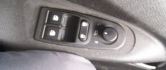
In order to be able to install central locking on VAZ cars, the manufacturer equipped them with a special BUBD control module. You can find it directly under the torpedo, on its left side. If this module is missing, it will simply not be possible to install the device, so before you buy an electronic lock, you should first find out whether the module is installed on the car.
Control module
The connectors of this module are equipped with 6 wires of different colors as standard. If you are installing an alarm system on a VAZ 2114, you will need to turn off brown and blue in order to get the following connection diagram:
Before you begin installing the lock, you should make sure that five-wire actuators are installed in the car doors. If it turns out that ordinary switches are installed instead of them, then it will not be possible to connect the alarm.
Another important point to remember is the need to purchase additional electronic components that are not included in the alarm kit.
These include:
- diodes 1N4001 for 1 Ampere - 3 pieces;
- three-amp diode 1N5401;
- any diode rated for a current of up to 5 Amps (only if there are no separate outputs for turn signals).
Diode wiring
Once these components have been purchased, you can begin connecting the alarm. To do this, you should carefully study the drawing with the connection plan included in the instructions (this diagram of the VAZ 2114 central lock is duplicated below) and carry out the entire installation procedure in accordance with it. So, in the diagram, the index X2 indicates the six-pin control connector (BUBD), which was mentioned at the beginning. This is where you should start connecting, guided by the same “native” circuit.
After the lock is connected, all that remains is to insert into the wires in order to connect the alarm to the door sensors.
Connecting door limit switches VAZ 2114
It is done in the following order:
- Remove the sill trim along with the side panel by unscrewing their fastening screws.
- In the exposed wiring harness, find the cable going to the door limit switches (it has a white and black color) and solder a 1N5401 diode into its gap so that the direction of possible current flow is only towards the limit switches.
- In the second wiring harness, find two blue cables, from which you should make taps (using a wire of the same cross-section) and stretch them to the location where the alarm is attached.
- Cut the handbrake wire and solder a 1N4001 diode into its gap with the cathode towards the limit switch.
Tapping into wires
If necessary, you can make an insertion into the wires even before connecting the alarm to the connectors - this will not affect the functionality of the electronic equipment in any way.
The next step is to connect autorun. To do this, you will need to power the alarm to terminal 30 of the ignition switch, and connect the yellow cable coming from connector X1 to its 15th connector (according to the connection diagram).
After the alarm is connected to the on-board power supply, you will need to connect it to the speed sensor by connecting the gray-black wire coming from connector X3 to the tachometer. After this, all that remains is to connect the black wire X3 to the ground connector in the main unit.
At this point, the installation of the central lock can be considered complete.
Installation
To begin with, I determined which wires in the control unit block I needed and which I did not.
I didn't need:
- — green wire — glass closer;
- — blue wire — trunk opening;
- — pink wire — siren (there was a siren, but I just didn’t want to install it);
Also, orange and orange-black wires are not needed, since according to scheme “C” they are not needed.
We still have:
- — red — “plus” 12v to the battery;
- — black — “minus” 12v (I connected the minus to the body, since the control unit does not necessarily require a minus power supply from the battery);
- — yellow and yellow-black — connect to the negative (I connected them to the main negative and all 3 wires to the body);
- - 2 brown ones - they supply a plus to the alarm button (some people connect them to the dimensions);
- — white — it sends a minus for closing;
- - white-black - it sends a minus to the opening.
For clarity
Used block with signatures
The control unit was installed on self-tapping screws, on the lower plastic part of the panel (to the left of the steering wheel height adjustment lever, next to the hood opening handle), but you can install it as you wish.
Plus, I stuffed it into the cambric and passed it through the rubber of the headlight range control, making a small hole with an awl (I couldn’t find a more convenient place, without drilling, in the whole car):
Positive wire
Under the hood I connected the plus directly to the standard terminal, tightening the bolt to “10”:
Positive terminal
I started connecting the emergency lights. I read on the Internet that you need to disassemble the hazard warning button, solder something, short circuit something, and in general it turns out that this round button interferes with normal steering and everywhere they show how to redo it.
In general, I did not find a complete pinout of the button, using a general electrical diagram and the scientific “poke method” I found out that:
- — blue-black wire — left turn;
- - blue wire - right turn
Hazard warning button block
I again stuffed the two brown wires into the casing and brought them to the emergency flasher button block, pulled out the blue-black and blue wires from the block, using a small awl and “someone’s mother,” and soldered the brown wires directly to the “mother” terminals, so how I didn’t want to cut off the factory terminals (you don’t need a lot of tin, because if there is a lot of it, the terminals won’t fit back into the block):
Emergency signal block with soldered brown wires BU
Removing the BUDU turned out to be not an easy task; it is located above the hood release handle, almost under the dashboard, in general in not the most convenient place.
I have installed BUBD 21093-6512010-03 NPO Itelma.
BUBD 21093-6512010-03 NPO Itelma
This BUBD was installed on all Samara II (VAZ 2113/14/15), I’m not sure about the Samar I (VAZ 2108/09/99), check whether the BUBD is the same on your car, because the pinout may differ.
The wires we need in the BUBD block:
- — brown — door closing;
- - blue - opening doors
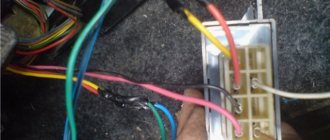
By analogy with the emergency gang, I soldered the wires to the terminals according to the diagram:
- — brown from BUBD with white from BU;
- — blue from BUBD with white and black from BU
BUBD block with soldered wires from the control unit
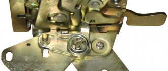
Now the most interesting part is the driver's door.
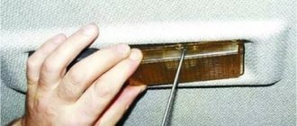
We remove the door trim, remove the black “anthers” from the inside.
There are several options:
Option 1) You have a certain “microswitch” in the driver’s door, which, when you open the driver’s door with the key, sends a signal to the ECU and it opens the other doors (another name for such a switch is central locking, since without such a switch you would have to close each door separately). The driver's door motor is missing. There is also a block with two wires in the driver’s door: one is red, the other is yellow (the same blocks are 100% in the other 3 doors of the car) they supply power to the electric motor, which opens/closes the door lock.
Option 2) Everything is the same as in point 1, but the block with the red and yellow wires is missing (a very common situation, especially if the equipment is not “Lux”). In this case, you need to pull these wires from the ACU to the driver's door (the diagram of the door lock system will be below).
Option 3) You have/have had a non-standard alarm installed and now you have more wires in the driver's door than in the entire car. Here I can’t tell you anything, since I myself have not installed a non-standard alarm system in Samara, try to figure it out using a diagram of the door lock system.
Shown here is an unmodified VAZ 2114/15 (may be the same as the VAZ 2109/99):
Door lock system diagram
We have the first scenario, which means we must first remove the “microswitch”.
Microswitch
Settings
After the alarm system on the VAZ 2114 is fully connected, its final configuration should be performed.
It is carried out as follows:
- Disable security.
- Set the ignition key in the lock to o.
- Press the button labeled Valet 6 times in a row.
- After the step marked “3”, immediately turn on the ignition (6 beeps should sound).
- Using the Valet button, select the required function (their list is given in the table below). To set it to the required value, press the corresponding key on the alarm key fob.
In this case, the most optimal (recommended) settings will be the following:
- for function 12 - value 3;
- for function 11 - value 4;
- for function 9 - value 3.
You can check whether the alarm is connected and configured correctly as follows:
- Disconnect the yellow cord coming out of block A91 from terminal 15 of the ignition switch.
- Turn the ignition key and start the engine.
- Pay attention to the alarm LED - if connected correctly, it should blink continuously.
The last thing I would like to talk about today is the importance of correctly connecting the tachometer, which directly affects the operation of the autostart.
To avoid errors, it is recommended to make this connection strictly in the following order:
- connect the red wire from the BUBD connector to the positive 12 volt terminal;
- connect the black wire of the 18-pin connector to the vehicle ground;
- Connect the gray-black wire of the same connector to the wire coming from the tachometer.
If you then turn on the ignition, then if the tachometer is connected correctly, the alarm indicator will begin to blink evenly.
How to remove it in detail
The 5-wire electric drive with its mounting was removed from the driver's door, and the wiring was also redone at the same time - the length of the harness in the driver's door was reduced, the 3-pin block under the central locking from the passenger's door disappeared. The pull from the lock has been removed. And away we go - alarm installers create whatever they want...
In our case, it looked like this:
The hole in the lock where the white rod from the microswitch is inserted and there is an old factory place where the rod is attached to the lock, is much more favorable from the point of view of kinematics than what the servicemen chose.
A smart solution, if you really don’t want to buy anything at all, would be to remove this rod, make a hole inside it in the center and insert a rod from an electric drive there, followed by attaching it to the main rod using a tie. I did this before converting it to the factory version.
We went a different way...
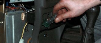
We unscrewed the 2 screws securing the microswitch housing...
... and took it apart out of curiosity
And here are the missing components:
- bushing for the door lock (2101 - something there), is easily available for sale - 5-wire electric door lock drive (21093 - something there, you can use any 5-wire one) - electric drive rod (set of 4 x pieces were ordered at one time from Tolyatti) - electric drive fasteners (rubber bushing + plastic bushing, 2 pieces, also from Tolyatti
The bushing was pressed into the lock. The bushing is pressed while heated, otherwise you will simply cut off one of its sides. Heated it with a heat gun.
Close-up of electric drive fasteners:
It’s in the door: — first the rubber parts
- then in them - plastic
That's all, factory parts are back in service, which are guaranteed to open the door to the summer heat and winter cold.