Review of the standard central lock Grants
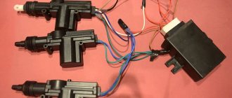
Before studying the principles of operation of the central lock, it is necessary to understand its composition. Such a system consists of the following elements:
- Central locking control unit.
- Door limit switches.
- Interior lighting.
- Actuators – horn and door locks.
- Remote control.
We will try to understand each element separately and analyze how the central locking on the Lada Granta works.
The principle of operation of the central locking system on Grant
The central link in this system is the control unit. It is he who processes all signals and issues “instructions” to actuators. The control unit sends impulses to the door locks and locks them.
Also, on command, it reverses the polarity on the locks and unlocks them. Limit switches are used to control the status of doors (open or closed).
The central locking unit needs this information to turn on the interior lighting and prevent the locks from locking with the door open to avoid damage to the drive or rods.
A remote control is used to control the central locking unit. It has three buttons:
- Opening.
- Closing.
- Opening the trunk.
To close the machine, you need to press “close”, to open it, press “open”. The trunk can be unlocked even if the car is armed.
To do this, hold down the button on the remote control for a few seconds - the trunk latch will be unlocked, and the trunk lid will not be taken into account. The lid must be closed within 30 seconds or an alarm will sound.
Any opening of the door while the system is armed is accompanied by a horn tone and the hazard warning light blinking. Thus, the car attracts attention in case of unauthorized access to the interior.
Additional features
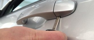
It is worth noting that the system can be controlled not only using the remote control, but also the corresponding key on the driver's door. By pressing this key, you can lock or unlock all the doors of the car.
This is convenient in case of a sudden attack by intruders or to protect children.
The Central Lock Grants provide the ability to automatically lock the doors when the vehicle is moving.
To do this, this function must be activated:
- Start the engine.
- Press the open and close button for 5 seconds.
- A beep will sound under the dashboard as confirmation.
Now, when you reach a speed of 20-40 km/h, the car doors will lock automatically. This will eliminate the possibility of a child opening the door at speed.
Another possibility is power window control. If you hold down the door lock button on the remote control for 3 seconds, the central locking unit will raise all the windows in the car - very convenient if someone forgot to close their window and the ignition was already turned off.
The unlock button works the same way – it opens windows.
Installation Guide
If you decide to equip your car with a car central locking system, this may be one of the options that will improve its security when the driver is not present. Moreover, if you have level hands, this is not so difficult to do. How should the installation be carried out and how should the reinforced central locking device be connected to the car? Before installing the system on a car with or without an alarm system, it is necessary to prepare for the work, including preparing an electrical circuit.
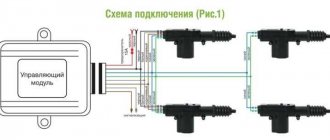
Central lock connection diagram
Tools and materials
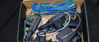
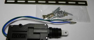
Installing a central lock with your own hands and connecting it to a car alarm begins with preparing the necessary tools, namely:
- central locking system kit, which includes the system itself, as well as an actuator;
- wire, it is better to give preference to two-core and copper wiring;
- other metalworking tool.
First stage
Before connecting the alarm to the central locking, you need to disconnect the battery. After all, these works will interfere with the electrical circuit, so it must not be allowed to short circuit.
So, the connection diagram for the central locking is as follows:
- To install and connect the central locking, you must first remove the door cards; to do this, disconnect the corresponding fasteners and unscrew all the bolts. In this case, each car has its own individual nuances that need to be taken into account, but in general, car enthusiasts usually do not have problems at this stage.
- After this, you need to choose the place where you will install the central locking system. To do this, pay attention to the operation of the window regulators - of course, they should not interfere with the system. It is quite possible that in order for the installed lock not to interfere, it will be necessary to make an additional bracket. As practice shows, usually the lower left corner of the door is the most optimal location for installation.
- Further, connecting the alarm system to the central locking includes the stage of installing the activator. Each solenoid is placed on a separate door; for installation you will need to drill the corresponding holes and secure the devices with self-tapping screws.
- Then the solenoid must be secured to the lock rod. It will be necessary to secure each solenoid from the kit using clamps. It should be taken into account that the rods on both locks (or on four, depending on the system) must be combined. After this, the activators need to install mounts on the rods of the manual central locking unit; this stage is also performed with each individual door of the car. When connecting the actuator components, it will be necessary to diagnose the wiring for voltage conductivity. If the hole in the lock rod is large, it is necessary to additionally use a plastic bushing - it will provide the required dimensions.
- Next, connecting the alarm to the central locking includes wiring. There are four cables coming from each solenoid - two to it, and two more to ground - they must be secured with plastic clamps. But in general, this stage is individual for each individual car - for example, you can use existing holes or drill your own with a drill. There is no need to lay the wiring from the bottom of the door, since moisture collects here. In addition, the wires from the solenoids must be carefully connected and routed from the opening between the car door and the body, since this moving part can damage the wiring. Use a rubberized tube for installation. When laying wires in the doors, make sure that they do not break when closing (the author of the video is SIMPLE THINGS).
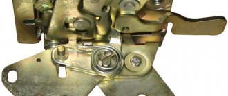
Malfunctions of central locking Lada Grants and solutions
The central locking is designed to ensure the safety of the car from intruders, but in order to maintain its functionality, it is necessary to promptly identify and eliminate malfunctions. Problems can be different and each has its own solution.
Fault table:
| Malfunction | Remedies |
| The interior lights don't go out, the central locking doesn't lock the door, or the horn goes off. | The limit switch of one of the doors is faulty. Replace the limit switch or clean it. |
| One door doesn't lock | Replace the door lock or repair the broken electrical wiring. It is also possible that the central locking unit may fail and must only be replaced. |
| Several doors don't lock | Malfunction of the central locking control unit - replace the unit. The battery in the remote control is dead - replace the battery. |
| Only one door is locked | Replace the central locking control unit. |
This is a small, but the main part of the malfunctions that can occur with a car central locking system.
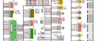
Detailed diagrams of nodes and blocks
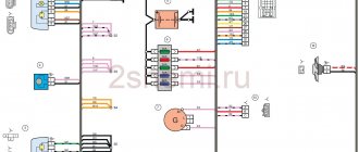
1 – right headlight; 2 – electric motor for washers; 3 – left headlight; 4 – VAZ-2190 starter; 5 – rechargeable battery; 6 – main fuse block; 7 – generator; 8 – sound signal; 9, 10, 11 – front wiring harness blocks to the instrument panel wiring harness blocks; 12 – reverse light switch; 13 – electric fan of the engine cooling system.
1 – oil pressure warning lamp sensor; 2 – generator; 3 – throttle pipe with electric drive; 4 – coolant temperature sensor; 5 – ignition system wiring harness block to the instrument panel wiring harness block; 6 – solenoid valve for purge of the adsorber; 7 – speed sensor VAZ-2190; 8 – mass air flow sensor; 9 – crankshaft position sensor; 10 – oxygen concentration sensor; 11 – controller; 12 – diagnostic oxygen concentration sensor; 13 – ignition coils; 14 – spark plugs; 15 – Lada Granta injectors; 16 – blocks of the wiring harness of the ignition system and the wiring harness of the injectors; 17 – knock sensor.
Electrical diagram of the Lada Granta lighting control module
1, 2 – rear wiring harness blocks to the instrument panel wiring harness blocks; 3 – right side direction indicator; 4 – left side direction indicator; 5 – hand brake sensor; 6 – rear window heating element; 7 – interior lamp; 8 – switch in the driver’s seat belt; 9 – trunk lighting; 10 – electric fuel pump module; 11 – right lamp; 12 – trunk locking motor; 13 – interior lamp switch; 14 – additional brake signal; 15 – left lamp; 16 – rear wiring harness block to rear left door wiring harness block; 17 – rear wiring harness block to rear right door wiring harness block; 18 – rear wiring harness block to the front right door wiring harness block; 19 – rear wiring harness block to the front left door wiring harness block; 20 – airbag control unit; 21 – rear wiring harness block to the wiring harness block for license plate lights.
Useful: VAZ-2101 diagram
Front right door wiring harness connection diagram
1 – block of the wiring harness of the front right door to the block of the rear wiring harness; 2 – electric window lift motor; 3 – right front lock Lada Granta; 4 – power window switch; 5 – blocks of the wiring harness of the front right door to the front right loudspeaker.
Front left door wiring harness wiring diagram
1 – block of the wiring harness of the front left door to the block of the rear wiring harness; 2 – electric window lift motor; 3 – front left lock; 4 – switch block; 5 – blocks of the wiring harness of the front left door to the front left loudspeaker.
Wiring diagram for license plate lights wiring harness
1 – wiring harness block for license plate lights to the rear wiring harness block; 2 – license plate light for VAZ-2190; 3 – license plate light.
Is it possible to install central locking on Lada Granta
There are Grants configurations (below Norma), where central locking is completely absent. Car owners who are accustomed to comfort are probably wondering whether it is possible to install a central locking system with a remote control on this equipment?
It is possible, but doing this with original kits is time-consuming, expensive and impractical.
The best solution is considered to be the immediate installation of an alarm system or a universal central locking system. Regardless of the path chosen, the steps will be the same. First, let's figure out what you need for basic installation:
- Control block.
- Drives for door locking.
- Limit switches.
Lada Grana is equipped with limit switches mounted in the body. Therefore, there will be no problems with their installation and there will be no need to buy an assembled lock, as on foreign cars.
After purchasing everything you need, all that remains is to do the following:
- Disassemble all the doors and install in each of them an electric drive connected to the lock rod.
- Lay the wires in the rubber corrugation of the door and connect them in parallel at one point in the cabin - where the control unit will be.
- Do the same with the door stops. Connect the wires to the central locking system according to the diagram, connect the control unit to power and test the operation of the door locks and limit switches. If everything is ok, move on to the next step.
- Connect the alarm part of the central locking system to the standard horn.
- Hide the control unit far inside the car. Preferably, under the dashboard - as much as possible, where only you can reach.
- Assemble the doors and all other parts of the interior.
Such a central locking system will differ from the standard one, but may have a lot of additional functions. For example, the Start-Stop button, which is very popular, as well as its own original control panel.
Connecting the signaling to the central locking system
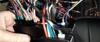
Now we get to the most interesting part. The contacts of the signaling relay must be connected to the gap in the brown wire (see diagram in Chapter 1). Moreover, this will be required regardless of the configuration. Oddly enough, we won’t need power cables at all. And the task now looks like this: you need a two-wire signal cable connected to the break in the brown cord.
Preparing for connection, completion
The moral here is:
- If you were able to remove the central lock control unit, connect the cable to the break in the wire connected to pin “7” of the control unit;
- If you have removed the door trim, then pull the cable out of it (from the point where the brown cord breaks).
It is clear that the second side of the cable must reach the relay connector of your alarm.
Option for the “Lux” package
So, this means that there is a button on the armrest in the cabin that allows you to lock the locks. From one of the contacts of the button, to which a “plus” is applied when pressed, you need to stretch the cord to the signaling unit. Nothing else is required, and you can connect the alarm according to the following scheme:
Scheme for the “Lux” configuration
According to reviews, this option is suitable if we are talking specifically about the “luxury” configuration. By the way, the resistor can be connected to the gap in the wire designated “blue” (the common contacts are then connected with a jumper).
It must be remembered that when working with any electrical equipment, you must first remove the negative terminal from the battery.
Each cord that is re-laid must not touch metal surfaces. Otherwise, in places of contact, the wire is protected with a tube that can withstand temperatures of 250 degrees. This is how you can protect yourself from unforeseen consequences.
Option for the “Norma” configuration
Let's say there is no button in the cabin that allows you to perform emergency closing. Then you need to connect the signaling to the central locking system according to the following scheme:
Scheme for the “Norma” configuration
As you can see, unlike the first option, there are no resistors here, and positive voltage is not used at all. But in the luxury configuration the effect that is characteristic of this scheme will not be observed:
- We perform closing from the key fob - all locks are locked;
- We try to open the locks with the key fob - only the driver's lock unlocks.
If you are satisfied with this property, try to implement the scheme in practice. And other options, more advanced, look much more complicated.
Read what is said about installation safety in the previous chapter. Do not neglect the advice about disconnecting the negative terminal. We work only with signal circuits, so nothing will fail even if connected incorrectly. However, be careful not to confuse the locking and unlocking relays, which are located in the alarm unit. This unit is usually equipped with a 6-pin connector (for details, see the signaling manufacturer's instructions).
How to replace the central locking control unit on Grant
The central locking unit on a Grant rarely fails, but if it breaks down it can cause a lot of trouble, for example, spontaneous opening or closing of doors, even if the car is just parked in the parking lot.
The central locking unit is located behind the fuse mounting block. To get to it, you need to:
- Remove the trim panel of the mounting block under the steering column.
- Remove the block from the mount and move it to the side.
- Unscrew the two fastenings of the standard alarm system.
- Disconnect the electrical connector.
- Remove the central locking unit and install a new one in its place.
- Reassemble in reverse order.
To avoid mistakes, you should know the article number of the new control unit - 21900651201000.
Programming the duration of control pulses
Even if the alarm is connected correctly, it is not a fact that the owner will be able to control the locks from the key fob. The point is that it is necessary to correctly select the duration of the control pulse (for locking and for opening). There is no need to make it too large so as not to overheat the actuators.
Screenshot of Starline signaling instructions
See what exactly the manufacturer Starline offers. We can set the pulse duration to 0.7 s, which should be enough. The value “3.6” will be redundant at the same time.
The “Lux” package has the following property: after 15 minutes of inactivity, the electronics “fall asleep”. It may take an extra boost to wake her up. So, try to use the option that provides for a double pulse. The main thing is not to activate the “comfort” option, which uses a 30-second duration. To connect the signaling with “comfort”, you need to install an additional unit in Grants (AvtoVAZ does not produce it). We wish you success.
Preparing the car before connecting
What controls the central locking? A special block to which the lock actuator wires fit. There are also two wires connected to it, connected to the driver's door microphone. More precisely, this wire is used alone in “Grant”, it has a brown sheath, and the second contact from the “micrik” is connected to ground.
The “micric” itself is located inside the actuator. So, the first piece of advice: after removing the left front door trim, you need to find the cable going from the actuator to the 7-pin connector.