A breakdown of the door, in particular its locks, not only causes discomfort for the motorist, but also calls into question the safety of personal belongings, so replacing the VAZ 2114 door lock is not a procedure that should be postponed. Since the quality of production and metal composition of domestic door locks leaves much to be desired, their breakdowns and failures occur quite often.
Trouble can await the driver at any moment when the driver’s door “suddenly” refuses to open and he has to get out through the passenger door. The situation is much worse when, if the lock breaks, the door remains open and the car remains “defenseless”.
Do-it-yourself alarm installation on a VAZ 2114, 2115
Installation of alarm systems on VAZ 2114 and VAZ 2115
In our example, we will look at the installation of an alarm model Starline A91.
Alarm systems from this company are perfect for installation on VAZ -2114 and VAZ -2115 cars
How to change the lock on the trunk of a VAZ 2113, 2114, 2115
Before installing an alarm on a VAZ - 2115,2114 car, you need to have a good understanding of the car's structure, and also decide what to connect to the alarm.
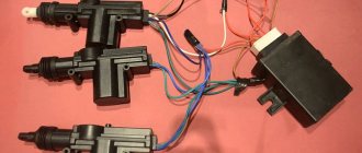
Connecting the central lock
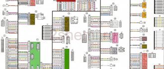
First you need to study in detail the connection diagram for the central locking on a VAZ car - 2115,2114. Finding it is not a problem by searching on the Internet.
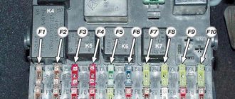
The central locking control module is located on the left under the dashboard. Looking there, you will find six wires coming out of the module housing. To install the alarm, you must disconnect the blue and brown cords. As a result, we get a connection corresponding to the following diagram:
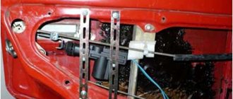
Before connecting the alarm, you should make sure that it is not a toggle switch installed on the driver's door, but a standard actuator with five outputs. Otherwise, you will need to install an actuator, which is quite problematic.
On VAZ -2115,2114 cars, the white wire, which is connected to the seventh terminal, is usually responsible for unlocking. If there are no connections at terminals 7 and 5, then the eighth terminal is connected to the brown cord. It is this cord that is responsible for unlocking in this case.
Terminals number five and six are responsible for locking the lock. This arrangement of contacts is typical for almost all blocks of the “ninth” series.
For some reason, none of the instructions for alarms ever indicate that installation requires the purchase of additional elements.
We will definitely need:
- Two to three 1N4001 diodes per Ampere
- One 1N5401 3 Ampere diode
- Two 4 or 5 Ampere diodes if there are no separate outputs for turn signals.
When installing a Starline alarm system, the task is greatly simplified, since significantly fewer additional parts are needed.
Replacing the ignition lock cylinder of a VAZ 2109 and the entire lock
Connection diagram
In this diagram, the designation X2 indicates a six-pin connector. It must be connected according to the diagram above. If you need to install an additional actuator, then it is better to use the diagram given in the instructions.
Now let's figure out how to connect the door sensors. For this purpose, there is a special wire in the connector marked X3.
Tapping into wires
Next to the driver's door, there are two wire harnesses running right along the floor. One of them has a cable coming from the parking brake and two wires to the turn signals. The second harness contains the door switch cable. This is where you need to start connecting. To do this, remove the sill trim along with the side panel. They are attached using self-tapping screws that must be unscrewed. Having done this, you can see the wiring harness shown in the photo:
This harness goes to the dashboard. We are interested in the door switch cable. If a 1N5401 diode is inserted into the wire break, the current should flow towards the limit switches. And the second diode 1N4001 is connected as shown in the figure.
At the same time, taps are made from the blue cables and the cords are pulled to the place where the alarm will be installed. And the handbrake wire is cut, and a 1N4001 diode is soldered into the cut with the cathode towards the switch.
Connecting autorun
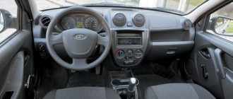
The VAZ-2114 models use an ignition switch with three terminals - 15 (blue wire), 30 (lilac) and 50 (red). Terminal 30 is connected to the battery. When you turn the key, blue wire 15 is connected to this terminal. The third terminal is responsible for the starter.
As it is written in the instructions, it is quite possible to power the alarm from contact 30, from which the lead is made. And the cable from connector X1, yellow, is connected to connector 15.
After all the actions taken, the connection of the tachometer remains. In this case, a loop antenna and a reading device are combined. Connector X3 has a gray-black outgoing wire. It is connected to the tachometer as shown in the VAZ dashboard diagram:
This will allow the alarm to control the speed. And at the very end we connect the ground from the main unit. This is a black cord from connector X3.
How to remove the ignition switch on a classic
Practical connection operations
To install a car anti-theft alarm you will need simple tools and materials:
- screwdrivers, wrenches (special pullers are not needed to dismantle interior elements of VAZ models);
- soldering iron and soldering accessories (solder, acid);
- multi-colored single-core cables (selected according to the colors of the standard electrical wiring or the pinout of a specific electrical circuit);
- linear meters and multimeter;
- insulating materials;
- fastening elements (special plastic clips are preferred).
The easiest way to find the central locking control unit is when installing the main car alarm control unit. For example, on the VAZ 2110 it is located rather inconveniently.
Most often, for the convenience of installing alarm elements, you have to completely disassemble the dashboard, door cards, remove the trunk upholstery, and disassemble electrical devices of lighting systems.
During installation, it is convenient to use wires of the same colors as those coming from the central locking control unit.
Having disassembled the door card, you can connect the control wires directly to the electric drive of the lock.
It depends on the car alarm model whether you need to purchase additional relays. Sometimes standard fuses and power switches may not withstand the additional load.
The easiest way to connect a car alarm to the central locks of VAZ models is to solder into the wire breaks (usually white and brown). To do this, you need to lay a four-wire cable from the two internal relays of the alarm unit to the eight-pin connector for controlling the door microswitches.
To avoid oxidation and damage to the integrity of the wires (this leads to false alarms), you must follow simple rules:
- carry out electrical installation work with the battery disconnected;
- connect electrical wiring only by soldering or terminals, insulate connections;
- use cables with a small margin in length, lay them in bundles, and securely fasten them to body elements;
- Observe the color of the cables for easy identification during alterations or repairs.
After completing the electrical installation work, do not rush to reinstall the removed parts. The final assembly of interior elements, doors, trim is carried out only after installing all elements of the anti-theft alarm system, making adjustments, and checking the functionality of the security system.
Connection diagram and setup
In the basic instructions, Starline provides a diagram for the A91 model:
Shown here is the harness going to the dashboard. Let's figure out what is connected where:
- The diode connected to the wire break must conduct current in the direction “towards the limit switches”;
- Above we talked about the 1N5401 diode;
- The second diode connected to the alarm wire may be designated 1N4001 (it is cheaper).
Now let's look at what is in the second bundle, located under the first:
From the two blue cables shown above, make T-shaped bends and extend the cords to the alarm installation location. And a 1N4001 diode is installed in the gap in the handbrake wire. The cathode of this diode “looks” towards the switch. Finally you will make the connections:
- The “green-yellow” and “green-black” wires from connector X3 are connected to the turn signal leads.
- Another tap coming from the cathode is connected to the “brake input” of the Starline A91 Dialog signaling system. The cord is designated as “orange-purple”.
It was discussed how to connect all the signal wires with your own hands. Queue for the security forces.
The steps listed in this chapter can be completed before installing the alarm. The functionality of standard equipment should not be affected.
Connecting the autostart connector
In VAZ 2114 cars, unlike the “nines”, an ignition switch with three terminals is used: 50, 15 and 30. The latter is connected to the battery, and contact 15 closes with it when the key is turned. Well, the 50th terminal is the “output "to the starter. Similar designations are used not only by VAZ.
As for model 2114, the lock escutcheon is secured with three self-tapping screws, as well as three metric screws. Unscrew them and you will see the following:
According to the basic instructions, power for the signaling can be taken from pin 30 (a T-tap is needed). And the “yellow” power cable coming out of connector X1 is connected to terminal 15. Further, if autostart is needed, then:
- The connections above must withstand significant current (up to 30 A);
- The “red” wire coming from the ignition switch is broken;
- The Starline A91 Dialog module is reached by bends coming from the break point;
- The thin wire from connector X1 should connect to terminal 50, while the power cord in “black and yellow” insulation will become the output to the starter.
Also, as stated in the installation manual, do not forget to cut the gearbox selector loop. The action makes sense if autorun is used.
Those who have an immobilizer activated in their car will have to install a crawler. You can buy a BP-3 unit from Starline to connect it to the “pink” control cord of the alarm:
All those who do not want to break the wire of the standard reader make a crawler with their own hands:
- The additional loop antenna contains 50 turns of PEL-0.3 wire;
- The internal antenna of the unit must contain the same number of turns of any wire;
- Both antennas are combined into a circuit opened by relay contacts.
The instructions cannot be completed here. The method of connecting the tachometer was not considered.
It is clear that the loop antenna will need to be combined with a standard reading device. And all the antennas included with Starline crawlers do not fit well with VAZ immobilizers.
The wire in “black-gray” insulation coming from connector X3 is connected to the high-voltage input of the tachometer (see figure). Your alarm will not burn out as a result, but will be able to control the speed:
All Starline security systems, as it turns out, are well compatible with any VAZ cars. This applies even more so to the A91 Dialog model. By the way, do not forget to connect the “ground” of the main unit (“black” cord of connector X3).
Software setup
We will configure only the functions responsible for autorun. You can activate the programming mode as follows:
- The security is turned off, the key in the lock is moved to the “0” mark;
- The Valet button connected to the A91 Dialog main unit is pressed 6 times;
- After step “3”, turn on the ignition immediately;
- 6 beeps sound;
- Use the Valet button to select the function number (see below);
- To set the required value, press the corresponding key on the key fob.
The system operates in Dialog mode, so the function number, as well as its value, will be displayed on the key fob. All the options in question are listed in the table:
Information was taken from the installation instructions. Switch the values of the following functions: 12-3, 11-4 and 9-3.
To set the value to “4”, press the third key until the melody appears. Then the button is pressed again. Having chosen the value 4 for function 11, it is better to perform the following check:
- The “yellow” cord coming from block A91 and connected to terminal 15 is temporarily disconnected;
- Start the engine “with the key”;
- The alarm LED should start flashing.
All these tips are given in the standard instructions. True, they advise disconnecting all wires except three.
How to connect
Installation of the VAZ-2114 alarm system begins with disconnecting the battery and determining the location of the elements. The control unit is placed under the instrument panel or behind the glove box, the siren is placed in the engine compartment. Guided by the instructions and diagram, all elements are connected.
The control unit is connected through connectors to system elements, components and vehicle parts. Installation and installation begin from the farthest point of installation of the security system element, using 9 connectors (X) for connection.
Sensors (limit switches) are installed in the engine compartment, under the hood and in the trunk, which react to opening. The door trims are dismantled to install activators. The Valet service button is installed in a place hidden from prying eyes, but easily accessible to the car owner.
A transmit-receive antenna is installed on the windshield in the upper corner. It is recommended to install the shock sensor inside the passenger compartment, securing it to a metal surface. The emergency siren is installed in the engine compartment with the bell facing down.
When all the elements are located in their places, you can begin to connect them into a single system.
Scheme
The characteristics of the Starline A 91 car alarm and the connection diagram of the main elements are given in the manufacturer's instructions. When connecting a 6-pin connector X 2, you may need an additional door opener activator.
When connecting door opening sensors, use the blue/red wire of connector X 3. All alarm connection points, i.e. connectors (X) look like this:
- X 9 - connect a two-level shock sensor installed on a metal surface.
- X 8 and X 7 - connectors are not used.
- X 6 - Valet service button, installed in a hidden and easily accessible place.
- X 5 - LED indicator, installed on the instrument panel.
- X 4 - transmitting sensor receiving module; it is recommended to install it in one of the upper corners of the windshield.
- X 3 - connector with many wires.
They are connected to the systems with wires of the following colors:
- Red - with the “plus” of the ignition switch.
- Green/yellow and green/black - sidelights and side turns.
- Black—vehicle mass.
- Yellow - ignition switch (connection to blue/black).
- Gray is the “plus” of the emergency siren.
- Blue/red - “plus” of the door entrance.
- Black/red - additional blocking relay.
- Orange/gray - hood lift sensor.
- Orange/white - trunk opening sensor.
- Orange/purple - to the brakes (according to the diagram in the instructions).
- X 2 - connect door opening activators;
- X 1 - ignition switch (closed with red wire).
Connecting the central lock
In basic configurations, the control unit (CU) of the central locking (CL) performs the function of locking the door lock. The electrical circuit connection diagram is the same for all central locks, the only difference may be in the control unit, activators and the number of pins for connecting an additional device.
The main elements of the central lock include the control unit, door sensor switches (limit switches) and microswitches that fix the position of the key. All these elements are connected to the alarm and interior lighting of the car.
To connect to the central locking, it is necessary to connect the central locking control unit (CU) to the car alarm using the door opening and closing relay, to the car ignition switch and to the door opening sensors. When installing the central locking, you will need additional parts, such as:
- diode 1A - 3 pcs.;
- 3A diode - 1 pc.;
- diode 5A - 2 pcs.
Tapping into wires
In order to insert into the wires, you first need to free them from under the threshold trim. To do this, unscrew the fastening screws and remove the upholstery. Underneath there are 2 wire harnesses running to the instrument panel. One of the harnesses contains the parking brake wire. 2 wires are connected to the sidelights and side indicators.
When inserting into the parking brake wire, 1 diode is installed, and 2 diodes are installed in the wire that powers the side headlights and side turn indicators. The terminals of the insertion wires are connected to connector X 3 of the alarm control unit.
Autostart
One of the functions of the Starlin car alarm system is auto engine start. In order to install with autostart yourself, you need to use the ignition switch wires. The lilac wire is connected to the battery. Blue (ignition switch) is connected to the alarm control unit via connector X 1.
To connect the tachometer sensor, it is connected to a gray/black wire coming from connector X 3. Connect ground from the main unit using the black wire of connector X 3.
Installing the central locking button - Club 2108
Today, almost all cars are equipped with central locking (CL), either it is standard, or it is installed together with an alarm system (well, if not central locking, then at least activator motors). Also, many alarms have the function of locking doors when the ignition is turned on and unlocking when it is turned off. This function is quite useful and can save your things from the so-called “purse grabbers”, who take everything that is not in your car when other people (dummy) distract you. If the doors are closed you are not in danger. But this alarm function is not entirely convenient, because... in order to pick up a person, or vice versa - to let him out, you need to either reach across the entire cabin, or turn off the engine, or use the alarm key fob. It is much easier to place a separate button in the car interior, which will fit well into the interior and will control the central locking. The easiest way to do this is to use the power window control button - this is exactly what you need. The button wiring is shown in the diagram, and the contact values are in the table.
brown to activator
white to alarm
brown to alarm
white to activator
You need to lift the trim in the driver's feet and find a harness there with wires of white, brown, black, red and yellow. Of these, we will need white, brown and black. Find the place where the alarm wires are connected to these wires and connect the wires from the table into the gap of these wires so as not to disturb anything. As can be seen from the diagram, contacts 1-6 and 3-7 are constantly closed, it is to these contacts that you connect, to contact 2 you connect ground (black wire in the harness). +12V is constantly supplied to the white and brown wires, the activator is switched by ground (pin 2). Contacts 4 and 5 are needed to illuminate the button, but keep in mind that an LED is used for illumination, and it is critical of polarity, of course it will not burn out, but it will not glow. The button can be placed in the driver's armrest (the trim can be easily cut with a knife), but I abandoned this idea, because... in this case, it is not accessible to the passenger, and I often leave my wife or friend in the car with the engine running while I run to the store. I placed the button in the place where the choke handle is located on carburetor chisels, i.e. under the immobilizer receiver: easily accessible to both the driver and passenger (if necessary), invisible to prying eyes, fits harmoniously into the existing hole for suction (you just need to work a little with a file, another plus - you don’t have to pull the wires too far.
Do-it-yourself engine start | Motorist's benefit
Probably, many have already heard about remote starting of a car engine; recently we have already published information about how autostart works and how it works. Those who are interested can read this article in more detail. Today we will talk about how to independently make a remote car engine start at home.
Adding the engine auto-start function to a regular alarm system
In this example, we will connect the autostart function to the StarLine A6 car security system. The image shows a schematic diagram of connecting all elements including the remote start module.
The image shows a schematic diagram of connecting all elements including the remote start module.
To connect you will need:
- Universal 4-pin relays – 2 pcs.
- Universal 6-pin relays (22.3777) – 1 pc.
- Schottky diodes SR360 (60A), analogue of diode 1N5822 60A – 3 pcs.
You shouldn’t have any problems assembling the circuit; the only nuance in this story is the low pulse duration of the additional channel on the StarLine A6 alarm (0.6 sec.) or long (10 sec. and 30 sec.), which in one case is not enough to turn on the starter , and in the other there is a lot of this. To solve the problem, it is necessary to reprogram the additional channel for 0.8 seconds, this is enough to start the starter. In the following photos you can see how the assembly and connection were carried out.
The photo shows the connection of diodes to output 85 of the starter relay
We hide the assembled circuit in the torpedo niche
The standard alarm program on channel 3 gives a pulse mode of 0.8 seconds. The first press of the button turns on the ignition, the second turns on the starter, only after 1.5 seconds the engine stalls and the ignition turns off. If the second time you press and hold the button, the engine runs until you release the button, this problem can be solved by reprogramming the alarm to supply a negative contact to certain relay contacts.
Before reprogramming, we have Relay 22.3777 supplies +12 current to the 4th contact when a minus appears and disappears on the 5th contact, and relay 21.3777 supplies a plus to the 4th leg as soon as a minus appears on the 5th.
After programming, relay 22.3777 supplies minus 12 volts to the 4th contact when a minus appears and disappears on the 5th contact, and relay 21.3777 supplies a minus to the 4th leg as soon as a minus appears on the 5th. As a result, we have a remote start with three clicks , and on the fourth, we turn off the engine. The positive aspect of this circuit is the presence of relay 22.3777, which makes a pause for the fuel pump (pause between the 2nd and 3rd press).
Troubleshooting
If a key or silumin rod breaks, you should not immediately buy a new block with a handle. On sale you can find special repair kits for VAZ 2108-099 door handles, which contain these parts in 2 copies.
This way you will save money and easily change the key yourself by removing the handle using the following sequence of actions:
- Remove the decorative panel.
- Disconnect the rod connecting it to the locking device from the handle mechanism.
- With the glass fully up, unscrew the 2 fastenings of the handle to the door card.
- Remove the handle, replace the parts and put it back.
If the rod is disconnected, then you need to remove the inner lining and put it in place, as described above. Using the moment when the facing panel is removed, check what caused the disconnection of this rod so that history does not repeat itself when the door is slammed.
Malfunctions of the locking mechanism can only be eliminated by removing it. In a situation where the device has a lot of wear, as happens on the driver and front passenger doors, it is recommended to replace the lock with a new one.
If you find an error, please select a piece of text and press Ctrl+Enter.
Correct modernization of VAZ 2114 limit switches
The most common problem in cars of this series is that the driver's door switch of the VAZ 2114 wears out and then does not work, so there is no need to talk about the normal operation of sensors, alarms and even lights in the cabin.
The second most unpleasant problem that VAZ 2114 car owners may encounter is that the standard limit switches do not report that the door is not closed when it is slightly open by one click of the limit switch. Such a design flaw not only does not allow the car owner to be confident that all doors are closed, but also leaves a significant loophole for intruders.
Therefore, if you want the signal to be triggered even when the door is slightly open, you will have to slightly change its design with your own hands.
Modernization of the limit switch of the VAZ 2114
The essence of the problem is to reduce the stroke length of the limit switch to obtain the required response of the entire electrical network.
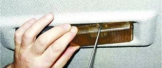
The simplest solution from available materials is the following modernization:
- We take the upholstery piston of your own car.
- We replace the standard “washer” with this piston.
- Using available means, measure the distance between the edge of the cap with the base; it should be 1 mm.
- We fix the design and check it; the light bulb in the cabin will act as a kind of quality control; it should light up after one click.
Although this method is not applicable for the rear door due to differences in design, it will help solve the problem of the front doors. Also, do not forget about fixing the piston; the ideal option would be a regular plumbing gasket of the appropriate size. On the back door, the limit switches will just have to be carefully ground off.
How to open a jammed door on a VAZ 21115
How to open a jammed door
at 21115 from the inside.
When the decorative panel is removed, the locking mechanism is accessible from the inside, although it is difficult to reach. Immediately check whether the rod going from the handle to the lock has disappeared. This is a fairly common malfunction that can be fixed with low blood pressure. Re-establish the connection and open the door.
If there are no visible reasons for the breakdown, simply try to open the door from the inside, acting on the mechanism using different tools. If necessary, have an assistant either push or pull the door from the outside. Experience has shown that these procedures for opening jammed doors can take a long time, so you will have to be patient.
Features of replacing the door lock cylinder on a VAZ 2114 car
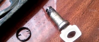
The larva has a cylindrical shape, which is activated when the key is turned in the well. If the mechanism jams and makes it difficult to open/close, then one day the driver simply will not be able to get behind the wheel of his car. Therefore, if the device does not operate correctly, it is recommended to replace the door lock cylinder with a VAZ 2114.
Reasons for replacing the VAZ 2114 lock cylinder
The mechanism is silent, but if an extraneous sound appears when opening the door element, the device will have to be dismantled or rebuilt. Replacing the front door lock cylinder on a VAZ 2114 is required for a number of reasons:
- a sharp drop in temperature;
- failure of the locking ring;
- loss of the fixing column;
- destruction of the plastic rod cap;
- wear of internal pins and teeth.
When individual parts wear out, they will cling to each other, blocking the rotation function. The main factor indicating a repair is turning the key.
Recommendations
Reassembling and lubricating individual parts will not work if the fragments are heavily worn. It is better to remove the cylinder from the core and install a new one. Recommendations for replacing the VAZ 2114 door lock:
- Partial repairs or lubrication will only temporarily restore life to the closing mechanism. If problems arise, it is better to replace the entire cylinder.
- After installation, it is necessary to periodically lubricate the mechanism. Experienced motorists use silicone substances for this.
- The repair procedure is carried out in a well-lit room at a comfortable temperature.
- To change the element, you will need a set of screwdrivers, pliers and lubricant.
- Sometimes the springs have to be replaced along with the cylinder. They are purchased separately.
The cylinder fragment is sold as a set. The price depends on the manufacturer. If you buy a cheap Chinese version, it will cost about 150 rubles. It is better to give preference to VAZ spare parts. The cost of such a kit is 400-500 rubles.
Withdrawal procedure
Depending on the reason, a complete or partial replacement is performed. It is not recommended for the average person to engage in reassembly, since there are too many nuances in this process, but almost anyone can replace the mechanism. Step-by-step instruction:
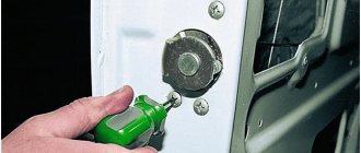
- Three screws are unscrewed. They are located on the inside of the handle. To do this, use a Phillips screwdriver to remove the cover.
- The front trigger glass position switch is removed along with the wiring harness block. To do this, the wires are first disconnected.
- The plug on the armrest handle is removed, the element is picked up with a thin corner of a screwdriver.
- Unscrew the 2 screws on the handle that hold the inner panel.
- The plastic clips are pressed out to remove the lining.
- 6 pistons are removed to remove the door card.
- The external fastenings are removed, the nuts are unscrewed with an 8mm wrench.
How to remove cravings
To remove this piece, you will need an impact screwdriver and a size 8 wrench. The piece is attached to the internal locking mechanism and the lock switch. Algorithm of actions:
- The internal lock of the outer handle rod is completely disconnected.
- The handle is removed along with the rods.
- The pin is removed from the end of the rods.
- The plastic tip is removed from the core of the cylinder device.
- The return spring is removed. The old larva is being removed.
Installing a new part
The removal and assembly algorithm is the same, although the instructions for installing the cylinder mechanism have its own nuances. Before inserting a new cylinder into the core, the part is lubricated with a silicone substance and only then inserted into the handle. Further algorithm of actions:
- The return spring is inserted next to the cylinder.
- The functionality of the key is checked. It should turn easily in all positions.
- A pin is installed on the tip of the rotary rod. Connection is being made.
- The inner and outer panels are screwed on, the handles are fixed, and the plug is returned to its place.
- The main three screws are tightened from the inside.
Trunk lock repair
As a rule, the trunk lock on VAZ cars lasts longer than door locks, which is caused by fewer openings/closings in an equal period of time. But, due to complete wear and tear (or loss of the keys), it still has to be replaced. In most cases, the lock mechanism itself, as well as its body, remains fully operational - only the cylinder into which the keys are directly inserted wears out. It will then need to be replaced with a new one.
To do this you will need:
- crosshead screwdriver;
- slotted screwdriver;
- a set of keys.
The trunk lock cylinder of a VAZ 2114 is replaced as follows:
- Open the trunk.
- Remove the plastic rivets (“hedgehogs”) holding the plastic socket around the lock by picking them up with a slotted screwdriver or a special extractor.
- Remove the panel.
- Unscrew the fasteners holding the lock.
- Remove the lock.
- Unscrew the fastening screws holding the cylinder in the lock and remove it.
- Install a new cylinder inside the lock.
Reassembling the lock and installing it in place is performed in exactly the same order, but in reverse order.
New lock cylinders are sold with keys inserted into the keyhole. You should not remove them before the cylinder is installed inside the lock, since this threatens its individual elements falling out, which will be extremely difficult to install in place.
After the VAZ 2114 lock cylinder has been replaced and the lock itself has been installed in place, you should carefully inspect its counterpart, called the latch (the lock tongue goes behind it when the trunk is locked). In most cases, there is no need to replace the retainer because it has no moving parts and has a very long service life.
Replacement may only be necessary if a crack appears on the body of the clamp (it is made of silumin). The replacement process itself is simple and consists of unscrewing the old fastener and installing a new device.
The only thing you will need to pay attention to is the correct setting of the lock. To check its quality, you just need to close the trunk lid and see how it locks. If locking does not occur, it is too tight, or, on the contrary, a noticeable play is felt, then the lock is not adjusted.
To configure, you need:
- loosen a pair of fastening bolts of the clamp;
- close the trunk (at this moment the latch itself will adjust to the location of the lock tongue);
- open the trunk;
- tighten the retainer mounting bolts.
If after the adjustment procedure the trunk begins to lock even worse, then most likely the mating part of the locking element is skewed. It is enough to unscrew the fasteners, place it straight without moving the lock itself, tighten the bolts - and the trunk will be easy to lock.
Common causes of breakdowns of VAZ 2114 door locks
- The door lock button does not lock and/or the lock cannot be locked with the key. This breakdown is typical when the upper end of the external drive lever is blocked, for example, on the shoulder of the handle.
- It is impossible to open the doors with the outside handle. Occurs as a result of an increase in the flange gap between the outer door handle and the lever in the lock drive.
- The central locking spring or the external drive lever has broken, as a result of which the door does not close.
- When closing the door, the lever tooth does not engage with the ratchet mechanism; this occurs due to the weakening of the rivets on the lever axis.
- The door does not lock because the lock lever is jammed or grease and dust are pressed into the lock.
- The door does not open completely with the inside handle. The position of the internal door lock lever is out of order, as a result the drive lever does not make full travel.
Replacement
The replacement process will take you no more than 10 minutes; the most difficult thing will be to unscrew the bolts securing the lock to the door. There is no need to adjust the lock after replacement, since the adjustment is made only on the hinge, and during operation the hinge will not unscrew and, therefore, will not change its position.
Tool
The only tool you need is a ratchet (driver) with a TORX T40 bit or a T40 wrench.
Step-by-step instruction
Attention: Under no circumstances unscrew both bolts at the same time; if you unscrew two bolts at once, the inner part of the lock (drive) will fall into the door and then you will have to remove the door trim to get it out.
- Unscrew one bolt and remove it
- Then unscrew the second bolt, but not all the way, pull the lock towards you and turn it to the side, or use a pin as shown in the picture.
- We screw the previously unscrewed bolt into an empty space and then unscrew the bolt securing the lock. This will prevent the lock drive from falling into the door.
We install the new lock in the reverse order, avoiding unscrewing both bolts at the same time.
Connection diagram and setup
In the basic instructions, Starline provides a diagram for the A91 model:
Shown here is the harness going to the dashboard. Let's figure out what is connected where:
- The diode connected to the wire break must conduct current in the direction “towards the limit switches”;
- Above we talked about the 1N5401 diode;
- The second diode connected to the alarm wire may be designated 1N4001 (it is cheaper).
Now let's look at what is in the second bundle, located under the first:
From the two blue cables shown above, make T-shaped bends and extend the cords to the alarm installation location. And a 1N4001 diode is installed in the gap in the handbrake wire. The cathode of this diode “looks” towards the switch. Finally you will make the connections:
- The “green-yellow” and “green-black” wires from connector X3 are connected to the turn signal leads.
- Another tap coming from the cathode is connected to the “brake input” of the Starline A91 Dialog signaling system. The cord is designated as “orange-purple”.
It was discussed how to connect all the signal wires with your own hands. Queue for the security forces.
The steps listed in this chapter can be completed before installing the alarm. The functionality of standard equipment should not be affected.
Connecting the autostart connector
In VAZ 2114 cars, unlike the “nines”, an ignition switch with three terminals is used: 50, 15 and 30. The latter is connected to the battery, and contact 15 closes with it when the key is turned. Well, the 50th terminal is the “output "to the starter. Similar designations are used not only by VAZ.
As for model 2114, the lock escutcheon is secured with three self-tapping screws, as well as three metric screws. Unscrew them and you will see the following:
According to the basic instructions, power for the signaling can be taken from pin 30 (a T-tap is needed). And the “yellow” power cable coming out of connector X1 is connected to terminal 15. Further, if autostart is needed, then:
- The connections above must withstand significant current (up to 30 A);
- The “red” wire coming from the ignition switch is broken;
- The Starline A91 Dialog module is reached by bends coming from the break point;
- The thin wire from connector X1 should connect to terminal 50, while the power cord in “black and yellow” insulation will become the output to the starter.
Also, as stated in the installation manual, do not forget to cut the gearbox selector loop. The action makes sense if autorun is used.
Those who have an immobilizer activated in their car will have to install a crawler. You can buy a BP-3 unit from Starline to connect it to the “pink” control cord of the alarm:
All those who do not want to break the wire of the standard reader make a crawler with their own hands:
- The additional loop antenna contains 50 turns of PEL-0.3 wire;
- The internal antenna of the unit must contain the same number of turns of any wire;
- Both antennas are combined into a circuit opened by relay contacts.
The instructions cannot be completed here. The method of connecting the tachometer was not considered.
It is clear that the loop antenna will need to be combined with a standard reading device. And all the antennas included with Starline crawlers do not fit well with VAZ immobilizers.
The wire in “black-gray” insulation coming from connector X3 is connected to the high-voltage input of the tachometer (see figure). Your alarm will not burn out as a result, but will be able to control the speed:
All Starline security systems, as it turns out, are well compatible with any VAZ cars. This applies even more so to the A91 Dialog model. By the way, do not forget to connect the “ground” of the main unit (“black” cord of connector X3).
Basic information about the car
When starting to install the alarm, you need to understand exactly where and what is located in the car, and what you will connect. Let's look at the connection diagram for the VAZ central locking system:
The control module is located under the dashboard on the left, and its connector attached to the body contains six wires:
When installing an alarm, the “blue” and “brown” cords are broken to obtain the following diagram:
The wiring of the 6-pin connector mounted on the main Starline A91 module is given below. Carefully study the principle of operation of the circuit: the limit switch here is in the “closed” position.
Before connecting the alarm to the ACU, make sure that a standard 5-wire actuator is installed in the driver's door, and not a toggle switch. It’s unlikely that anyone will be able to install the actuator with their own hands by running two cords to the engine in 5 minutes. In general, it is sometimes better to refuse to connect the signaling system to the central locking system.
Let us take the liberty of revealing VAZ’s proprietary secret:
- If you see a "white" control wire connected to terminal "7", it is responsible for unlocking (as opposed to the "brown" one);
- If terminals “5” and “7” are not used, a “brown” cord will be connected to terminal “8”, and it is then responsible for unlocking.
The locking contacts are terminals 5-6. The two outer terminals are responsible for unlocking. This is true not only for model 2114, but also for BUBD units of the “ninth” family in general.
The instructions for the alarms usually do not say that you will need to buy additional parts before installation. These include:
- Diodes 1N4001 (2-3 pcs.) – designed for current up to one Ampere;
- 1N5401 (1 pc.) – three-amp diode;
- To install any car alarm that does not have separate outputs for turn signals, you need to purchase two power diodes (4-5 Amperes).
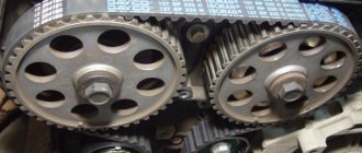
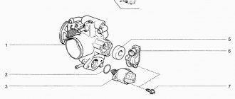
CONSTRUCTION OF CONVENTIONAL AND SILENT LOCKS
Before we talk about how silent locks work, let us remind you of the door lock design of the VAZ 2114. This locking mechanism of the car consists of several elements:
- The inner housing in which the rotating unit is placed. It is the main door locking mechanism.
- The cylinder, which is connected to the rotary unit, has an individual design that matches the outline of the key. The key is inserted into the cylinder and sets in motion the rotary unit, which opens the door. A button on the door is connected to the body, locking it.
- Rods that control the door handles are connected to the lock body.
- In modern models, a gear motor is associated with locking, which turns on the alarm.
- The locking device, which provides locking, is attached to the car body.
- The operating principle of silent locks on VAZ cars is based on sound insulation of metal parts. To be more precise, the noise-insulating material covers the locking mechanism pin and the metal latch that are in contact with each other. Plastic is more wear-resistant, but rubber absorbs sound more effectively.
- In addition to this, the locking parts of the lock are treated with silicone, which provides additional sound insulation.
The so-called silent bolts, which are used to fasten and are required to complete all silent locks, have a good soundproofing effect. The essence of their noiselessness lies in the plastic clamp, which is put on before the thread. Silent bolts for the VAZ 2114 can be bought at an auto parts store, or you can try to make them yourself. How, you will learn about this below.
Silent locks for VAZ, produced by Ptimash in Dimitrovgrad, enjoy a good reputation.
Door opening method
If the VAZ-2109 door does not open from any side, then the cause of the breakdown is difficult to determine, since there is absolutely no access to the lock mechanism.
A somewhat simplified version of the breakdown occurs when the door does not slam shut completely and gets stuck in that position. Then it is possible to reach the latch from the outside with a sharp object.
To open a jammed door, you must first perform the following steps:
- When the sash is not completely slammed, try to get to the locking device using a steel flat ruler. It may be possible to open it in a similar way to conventional door locks with a latch.
- If the door is completely closed, try to move it to the slightly open position to gain access to the lock. To do this, try pressing the inside and outside handles together or alternately, while simultaneously pushing the door from the inside.
- Try opening the back door with a helper, who will press and release it to get it into position while you try to open the lock.
When simple means do not produce results, the door will have to be opened from inside the cabin, which will require removing its trim.
How to connect a button?
The driver and passenger door buttons are connected to each other, as well as to the ESP motor and power cable. Correct pinout of the power window button:
- Pin 1 on the driver's door is connected to pin 6 on the passenger side. Contact 1 on the passenger door is connected to the negative terminal of the ESP motor.
- Pin 2 on both buttons is connected to power.
- Pin 3 is the ground on the driver's side and the positive wire on the passenger's side.
- Contact 4 in both cases goes to the headlight switch.
- Contact 5 is ground in all cases.
- The positive wire of the ESP motor corresponds to pin 7 of the passenger door button.