The ignition switch in cars of the VAZ family fails from time to time due to weakening of the contact posts or burning of the contacts inside it.
It also happens that the cams of a plastic roller are produced. You can disassemble the lock and clean it, but it’s better to just replace it with a new one, considering that it costs pennies compared to imported locks. But if connecting the wires together did not result in the starter operating (or it did not turn on the first time), check the solenoid relay on the starter. The contact spots on it may also burn out, which will prevent the circuit from closing normally. Alternatively, you can use a screwdriver to short-circuit the two large terminals on the solenoid relay (before doing this, put the car in neutral and use the handbrake). When closed, the starter should begin to spin vigorously. If this happens, remove and change the solenoid relay. If the starter rotates “sluggishly” when it closes, you will have to remove it and check the condition of the brushes.
All operations are performed with your own hands, without the help of car service specialists. Moreover, the price of an ignition switch on a VAZ2106 is up to 100 rubles. To replace it, you will need to know the pinout of the wires coming from it, for which the editors of the site 2 Schemes.ru have prepared a large reference material.
The ignition switch is designed not only to start the engine - it performs several functions at once:
- supplies voltage to the vehicle’s on-board network, closing the circuits of the ignition system, lighting, sound alarm, additional devices and instruments;
- at the driver’s command, turns on the starter to start the power plant and turns it off;
- turns off the power to the on-board circuit, preserving the battery charge;
- protects the car from theft by fixing the steering shaft.
How it works - studying the ignition switch
The operation of the ignition switch is based on a mechanism consisting of a switch, which, when the key is turned in the lock, connects different types of contacts. As a rule, the ignition switch operates in several positions, each of which is responsible for a specific action when starting the car.
The first position is responsible for turning on the instruments on the panel and distributing power consumption throughout the car. The second position is responsible for starting the engine. Well, the last mode is the steering wheel lock. For each position, its own contact group of the ignition switch is activated to one degree or another.
Ignition failure is a fairly rare occurrence and not every motorist experiences this. However, if you can barely get to the nearest service station with a broken tire or a malfunctioning generator, you won’t get far with a broken lock. Let's figure out why this problem can arise and how to fix it yourself.
Electrical wiring of VAZ 2104: features and differences
Did you like the article? Follow our channel for new ideas of useful car tips. Subscribe to us in Yandex.Zen. Subscribe.
The success of the VAZ “penny” significantly influenced the development of the domestic automotive industry. On its basis, a whole series of cars was created, among which the VAZ 2104 stood out noticeably for its overall dimensions. The increase in the base led to the fact that the electrical wiring of the VAZ 2104 had its own characteristics, which will be discussed in this article.
Tip: not only different body shapes, but also different power units influenced the electrical circuits of the car. This should be kept in mind when servicing your car yourself.
Design and principle of operation of the ignition switch contact group
The need to use a contact group in a car’s ignition system is dictated, first of all, by convenience, reliability of the connection and grouping of wires included in the electrical circuit. In addition, the use of a contact group as an intermediate link between the consumer and the ignition switch increases the degree of maintainability of the latter.
The design of the ignition switch installed on classic VAZ models is nothing more than a traditional electrical circuit breaker. The key in this design plays the role of a contact position regulator, capable of performing several standard contact closure options corresponding to certain vehicle operating modes:
- starting the power unit;
- connecting power to electrical devices;
- stopping the power plant
The connection of wires of the “socket-plug” type ensures high reliability of contact, and special fasteners in the plastic housing of the group act as an insulator (distributor) that prevents the occurrence of short circuits. Thus, the contact group of the ignition switch is nothing more than a device that connects all consumers into a single system via electrical wires (see figure).
The contact ignition system used on classic models of VAZ cars can be of two types: generator and battery . The difference between these systems is that one of them has an autonomous power source (battery), which allows the use of electrical appliances when the engine is not running.
The operation of the ignition switch contact group is based on the following principle. Turning the key closes the electrical circuit from the “-” terminal of the battery through the ignition coil to the “+” terminal of the battery. The current passing through the coil is converted into a high voltage pulse, generating a spark discharge at the spark plug electrode. Consequently, turning the key initiates the start of the car’s power unit. The inclusion of other electrical circuits that ensure the functioning of elements of the electrical equipment of the vehicle is carried out by installing the ignition key in the appropriate positions, causing the closure of certain groups of contacts.
Depending on the car model, the same key positions in the ignition switch may correspond to different groups of contacts, and, consequently, different operating modes of electrical equipment. An option is possible in which voltage is supplied at the moment the key is installed in the ignition switch, that is, the key itself closes the circuit that supplies the supply voltage. The functioning of anti-theft and alarm systems, devices that block car doors, etc. is organized in a similar way.
The procedure for disassembling the lock
Before starting work, you should prepare the necessary set of tools. The kit will come in handy with a Phillips screwdriver, a set of keys, a narrow chisel or punch, and round nose pliers with curved ends for gripping. Provide yourself with easy access to the lock and adequate lighting.
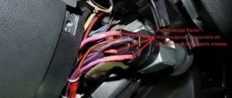
At the initial stage, the entire device assembly is removed. The protective element of the plastic casing is sequentially dismantled, the lock is unscrewed and pulled out. To avoid errors during reassembly, mark the installation location and purpose of each wire. Take the time to take a legible photo.
Be sure to evaluate the terminal block with the wires inserted. If cracks or traces of melting are detected, feel free to remove each wire from its socket and replace it with a new part.
There is no clear answer to the question of how to remove the ignition switch contact group. It all depends on the design features of the device. Let's consider dismantling the required element using the example of the VAZ model of the 10th family:
- Disconnect the backlight wires if present.
- Disconnect the decorative cover at the top of the device by unlatching the latches around the perimeter.
- Disconnect the contact group. Usually the fastening is also carried out in the form of several clamps.
After removing the part, you should examine the condition of the contacts. Minor oxidation can be removed by simply sanding with medium-sized sandpaper. Do not rush to reassemble. Try to simulate a launch right on the scale.
If burnt contacts are detected or if it is impossible to identify a visible defect, the part should be replaced without regret.
When performing reassembly, consider the sequence of operations. A well-installed lock should not only perform its functions, but also not move with each turn of the key. Please pay attention to the following points:
- the mounting bolts are firmly tightened only if the outer part under the steering wheel is properly installed;
- make a test rotation of the steering wheel without a key to make sure that the locking device is working properly;
- When selecting bolts, do not forget about the ease of access to the lock for potential burglars.
When completing all work and connecting the wires, check that the harness is securely fastened. If everything is done correctly, the first test run will allow you to hear the rustling sound of a running engine.
Ignition switch: circuit, device, operation
In order to understand how it works, you need to understand what the ignition switch consists of. Like any other contact electrical device, it has a mechanism that connects and disconnects the electrical wiring circuit. In addition to turning the ignition off, the lock also performs some functions that are activated when you turn the key:
- in position No. 1 - power is supplied to the instrument panel and various electronic devices;
- in position No. 2 - the engine is started;
- in position No. 3 - the steering wheel is locked.
Each of these key positions uses its own ignition switch contact group.
The ignition switch does not break down as often as other parts of the car's electrical equipment. If the ignition system lock is faulty, you can determine the cause yourself.
Wiring sequence
When the ignition switch is turned on, the starter does not turn. Why does the starter not respond to turning the ignition key? It also happens
If you are lucky and have a special chip for connecting the lock, everything is simple. But if such an element is missing, then the wiring will have to be connected one by one. To do this, you need to take the terminal block of the inserted lock so that one double-type terminal is located on the right and stands vertically. The top of this terminal should have black wire attached to it.
Next, you should work in the direction of movement of the clock hand. The pink wire will be connected second, followed by blue, brown, and the whole thing will be completed by a red wire. It should be noted that on the rear block of the lock near the terminals there are numbers, each of which corresponds to a specific wire.
Remember that the bottom area of the double view terminal must be left empty. So, the contacts are connected.
How it works
The group of contacts in the ignition switch is a system for connecting wires in the required sequence and order, for this there is a start, ignition and parking position. This ensures correct distribution of on-board voltage from the current source, which in a car is the battery, to consumers. There are many of them in a modern vehicle, these include ignition and engine starting systems, lighting, alarm systems, control, monitoring, and security systems.
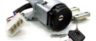
The contact group works together with the ignition switch; in some cases, when the ignition switch cylinder is broken, there are options for it to work independently, or an additional start button is installed. Below is shown how the ignition switch of a VAZ 2101-2107 works.
1. Anti-theft rod; 2. Product body; 3. Shaft with splines for turning the contact group; 4. Disk with contacts; 5. Bushing with contacts; 6. Contact connector.
The letter “a” shows the guide for correct assembly of the lock components. As can be seen from the figure, the device circuit is compared with a conventional electrical contact breaker. The key in it acts as a kind of regulator of the order of commutation of certain circuits. The first ignition switching devices were made as one piece, this simplified and reduced the cost of their production, but there was one significant drawback. If the contacts suddenly burned, broke, or oxidized, the lock had to be completely replaced. Therefore, a design for an easily replaceable contact group was developed.
Pinout of lock VAZ-2108, VAZ-2109, VAZ-21099
Pinout according to the old type
Daewoo Nexia Capricious girl Logbook Unloaded the Nexia ignition switch
Pinout of the VAZ-2109 ignition switch with unloading relay:
- comes +12V in position I, II, III (parking)
- comes +12V in position I, II, III (parking)
- comes +12V in position III (parking)
- position I, +12V goes out after turning on the ignition (contact 15/2), disappears at start (II);
- position I, +12V goes to the starter (pin 50);
- position I, +12V goes away after turning on the ignition (pin 15), does not disappear when starting II;
- +12V comes from the battery (pin 30);
- comes +12V constantly.
New pinout type
Pinout of the new VAZ-2109 ignition switch:
- comes +12V constantly
- comes +12V constantly
- +12V arrives after turning on the ignition (pin 15), does not disappear when starting II;
- +12V arrives after turning on the ignition (contact 15/2), disappears at start (II);
- position I, +12V goes to the starter (pin 50);
- +12V arrives after turning on the ignition (pin 15), does not disappear when starting II;
- +12V comes from the battery (pin 30);
- comes +12V constantly.
A few words about the principle of operation
Modern cars and trucks have a battery ignition system that uses the battery as the power source. When you turn the key, power supply voltage is supplied to the vehicle’s instrument panel, electronic control unit and other systems of the vehicle’s electrical circuit. A further turn of the key makes a connection through an additional starter relay to start the engine.
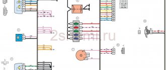
The figure shows the electrical circuit of the ignition switch, which shows the principle of operation of the switch
Almost all switching of consumers is carried out by the contact group of the lock. Different models of machines have switches that differ from each other in their operating algorithm. There are models in which only installing the key supplies voltage to individual systems. Recently, the start button has become widespread, as well as the stop button. This installation allows you to use it instead of a lock, the power unit is started and at the same time the starting circuit is unloaded. The button used should not have a fixed on position.
The same start button is often installed by car owners themselves, especially those who do not have an unloading relay. Typically, a button with the start function has powerful power contacts; only they can relieve the contact group from the starting current of the starter solenoid relay. Switching circuits with high current requires the use of high-quality materials to produce a device that can withstand high temperatures from heating and have good insulating qualities.
Scheme
Typically, connecting a lock does not involve much difficulty. The scheme is quite simple and practically does not differ depending on the brand of car. If each wire is connected separately, remember the following points:
| Key phase | Terminals (live contacts) | Chains |
| 0 | 30; 30/1 | No connection |
| I | 30-INT; 30/1-15 | Function:
|
| II | 30–INT; 30/1–15; 30–50 | Position II circuits as well as starter |
| III | 30–INT; 30/1 |
|
What you should also pay attention to:
- INT – black wire;
- terminal 15 – blue wire with a black stripe;
- terminal 30 – pink wire, and at 30/1 – brown;
- terminal 50 – red wire that ensures the starter operates.
What you need to know about node malfunctions
They come in two varieties:
- Damage to the lock or its cylinder;
- The ignition switch contact group has failed.
Switch failure is quite a rare occurrence for “branded” parts, which cannot be said about “consumer goods” from China or Hong Kong, which can bring surprises to car owners. We will not consider problems with switches; we will focus on faults of the switching unit. Several factors also indicate breakdowns:
- The machine's electrical consumers do not turn on;
- The engine starting system does not work.
In both cases, to make a final decision on how to fix the breakdown, you should check the serviceability of the unit. This is not difficult to do if you have a car tester and retain your knowledge of electrical engineering. To check, you need an electrical diagram of the lock, which today can be easily found on the Internet. If all this is available, start working.
The photo shows the switching group testing element.
To carry out this “undertaking” you need to have access to its contacts or connector with wires. In some cases, you will have to dismantle the device. This applies to a greater extent to cars of the Zhiguli family of cars. The key is moved to the first position, and the device measures the resistance of the corresponding contacts; the lock diagram will tell you about this. Their resistance should be close to zero. Next, you should take a measurement in the second position of the key. In the stop position, power should be supplied to the car radio, clock and other devices. The diagram will also show all this. If the device readings approach infinity, the group will have to be replaced.
Remember! Cleaning the contacts with fine sandpaper will restore operation in the short term.
During Soviet times, drivers used silver-coated coins to restore contacts; this solved the problem for some time. You can still apply this old-fashioned method today. The contact group of the lock is a delicate thing, so you should treat it with caution.
Conclusion
Car and key memory is a useful function, as is the entire anti-theft system in principle. However, you should not assume with confidence that such a car cannot be stolen by criminals. As practice shows, car thieves improve their skills and knowledge along with car manufacturers, which is why they always find a way to steal a familiar car. That is why you should not limit yourself only to the standard memory of the car and the key. It is necessary to use additional protection methods, especially when it comes to a new car purchased for a large sum of money.
Author: Oleg Mokrov
How to extend service life
This is easy to do on those cars where there are no relays for the start or stop position. Installing auxiliary relays yourself helps with this.
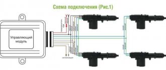
The figure shows the connection diagram. Typically, such relays are mounted in circuits “30” and “15” of the lock, which is almost the same for all models. The exception will be the Moskvich and Volga cars, the switches of which are designed slightly differently. 30 Amp relays from the VAZ 2108 or 50 Amp relays from the VAZ 2110 are suitable as auxiliary relays. In “old” models, start buttons are mainly used. In a similar way, the circuit is unloaded along the circuit “30” - “50”. There are options for homemade modernization, when instead of one relay, two devices are installed in a parallel circuit. The circuit becomes somewhat more complicated, but the service life of the relay is extended.
Location
For most domestic and foreign cars, the ignition switch is structurally located in the steering column housing or under the panel of technical sensors. The contact group is located behind the plane of the ignition key cylinder.
It is typical for many vehicles to install the ignition switch on the right or left side of the steering column. Sometimes there are foreign car models where the lock and key are located on the car's dashboard or navigation panel.
This is interesting: 2 methods of cylinder block liner: features of repair work
And finally...
To summarize, let's say that for the ignition to work correctly, you need to use the original key, try not to lose it, and also remember that the starter serves as the element that replaces the crooked key. There are four main reasons why you might need to replace your lock, but the most common is losing your keys. Remember that it changes when the power is turned off.
It is difficult to imagine a modern car or motorcycle without one small part that provides protection and control of the vehicle - the ignition switch. Read about the purpose and role of the ignition switch in a car, its design and operation, as well as its typical malfunctions in this article.
Characteristics of a contact group
To begin with, we suggest finding out why an ignition switch contact group is needed, what its structure is and how it works.
Purpose and functions
In essence, KGZZ is used to ensure the connection of all electrical circuits of the vehicle without exception. That is, when the driver turns the key in the lock, the KGZZ closes the contacts, thus allowing the use of all electrical devices without exception.
Device
Diagram of the lock The ignition switch itself is a simple circuit breaker.
When you turn the key, the contacts are adjusted, making it possible to start the engine, power the equipment, and also stop the power unit. If you disassemble the body of the lock itself, you will see that the device itself is located inside it, as well as a large number of wires connected to each other. The wires to the lock come from the battery. The contact group of the ignition switch itself goes directly to the connection point of these electrical devices. To prevent short circuits and to delimit the contact elements themselves, the KGZZ is mounted in a plastic case.
Principle of operation
An automobile ignition system can be either battery-based or generator-based. Their fundamental difference is that battery ignition is equipped with an autonomous power source; accordingly, all electrical equipment can be turned on without starting the engine. As for the generator system, in this case, activation of electrical equipment is possible only after starting the engine.
When the driver turns the key in the lock, the electrical circuit contacts are closed from the negative terminal on the battery to the coil. At the same time, voltage begins to flow through the wiring to the lock, which is supplied to the coil through contacts, after which it returns to the positive output of the battery.
At the moment when the voltage passes through the coil, a very high voltage is generated in it, which is subsequently transmitted to the spark plugs. Ultimately, the contacts close and the engine starts. In addition to the ignition circuit itself, there are other electrical circuits in the car that conduct voltage from the key to electrical appliances. Each of the wires is responsible for connecting the contacts to each other (the author of the video is the Auto Repair and Maintenance channel).
Basic faults
Briefly about the reasons why repair of the ignition switch contact group may be required:
- Overloading of the device, which may be due to the installation of additional devices of increased power, as a result of which a higher voltage will pass through the KGZZ. For some time, the device can cope with this current, but over time, carbon deposits will begin to form on it. It should be noted that this deposit, as a rule, appears precisely inside the contact, and not on its surface, then the only way out is to replace the contact group. To prevent this problem, all additional devices must be connected via fuses or relays.
- Short circuit in the electrical network. If a short circuit occurs, this may also cause high power voltage to pass through the CGZZ, which again will cause its failure.
- Many motorists who changed the KGZZ faced the problem of abrasion of the tracks, as well as the contacts themselves. This problem usually occurs as a result of wear and tear on the lock, but in some cases the cause may be faulty.
- Mechanical failure of contact elements, as well as other components of the group.
- Overheating of the device, which can lead to damage to the design of the CGZZ. Overheating, as a rule, also occurs as a result of increased load on the device. When working in conditions of elevated temperatures, the tracks may move or even break (video author - AlexAvtoKhlam).
Reasons for replacement
Many problems associated with the ignition switch can be eliminated by replacing only individual parts, and not the entire switch as a whole. You can buy a contact group or a lock cylinder separately. That is why repairs should begin with high-quality diagnostics. Main malfunctions and their symptoms:
- The starter does not respond to turning the key. The reason is most likely in the contact group. To verify this, check whether power is supplied to the starter relay after turning the key to the On position (starter activation mode). If the relay clicks, it means that the system “sees” the key being turned and there can be no complaints about the components of the electrical circuit of the lock. On vehicles that are not designed to have a starter relay, the power should be checked at the corresponding terminal of the solenoid relay. For diagnostics, you can use a multimeter or a tester (one lead to ground, the other to the retractor contact coming from the ignition switch). If the retractor and wiring are in good condition, then the contact group has failed;
- the key moves with a wedge. The problem is in the lock cylinder, as over time the mechanism wears out and becomes clogged. In this case, aerosol lubricants can only temporarily eliminate the malfunction;
- The key does not turn to all positions. The reason is mechanical damage to the lock cylinder. It may also be due to jamming of the anti-theft locking mechanism of the steering shaft;
- the key turns, but power does not come to the corresponding groups of contacts. The reason is in the contact group. The pinout of your vehicle's ignition switch can be found in the repair and maintenance manual.
Replacing the lock contact group
The ignition switch contact group is an element exposed to high temperatures, especially when the vehicle’s power unit is started. This happens as a result of an increase in the temperature of the electrical wire conductor (due to sudden voltage surges), which provokes burnout of the insulating material of the contact group.
Installing an additional unloading relay, which partially removes the load when the engine starts, can protect the contact group from the occurrence of the defect described above. Nevertheless, this phenomenon is quite common among the VAZ “classics”. And the only solution to the problem that guarantees further uninterrupted operation of the ignition system is to replace the contact group .
The process of replacing a contact group is quite simple, and this applies equally to the technical features of the procedure, and to the provision of tools and repair skills. The main point that requires some attention and scrupulousness is compliance with the contact connection diagram. It must be absolutely identical to the old one. In addition, information about the connection diagram is located in the vehicle's operating instructions.
So, we change the burnt-out contact group of the ignition switch:
- Disconnect the battery terminals.
- Unscrew the screws securing the plastic steering column cover and remove it.
- Unscrew the screws (2 pieces) securing the lock.
- We set the key in the ignition switch to position “0”, which ensures that the anti-theft device is turned off.
- When disconnecting the lock from the network, mark the wire contacts.
- Having removed the retaining ring, disconnect the contact group from the lock and replace it.
- Assembling and installing the lock in its original place is performed in the reverse order to that described above.
Let's sum it up
As you can see, ignition switches may differ from each other in connection type, functionality, purpose and other parameters. At the same time, all of them are structurally quite simple, which makes it possible for any car owner to correctly troubleshoot problems when identifying a malfunction.
As a summary, we note that the presence of a chip simplifies the connection, but this solution is often missing on older models. To avoid mistakes, without enough experience in this case, it is better to contact an experienced auto electrician who will quickly fix any problems with the ignition switch.
How does the engine start button work? Available options and solutions for installing the starter button yourself. How to install the engine start button yourself.
How to remove the engine start lock. Checking for random activation of the immobilizer and how to disable it. Diagnosis of possible alarm malfunctions.
Why the starter may not work after turning the key in the ignition. The main causes of starter malfunctions: bendix, traction relay, brushes, winding.
The alarm in the car does not work: there is no connection with the key fob or the main module is faulty, how to determine. Methods for emergency shutdown of alarms, tips.
The car alarm does not work: the main reasons for car alarm failures. How to accurately determine the reason: the key fob or control unit does not work.
Starline alarm with auto start: how to set up Starline auto start. Enabling Starline autorun remotely or automatically.
Checking the functionality of the ignition switch contact group
Diagnosis of the suitability of the ignition switch contact group is carried out with a device - a multimeter. The contacts are checked for changes in resistance.
Sequence of work
The performance of the part is checked in the following sequence.
- Disconnect the battery (you can only remove the “-” terminal).
- Disconnect the contacts of the wire block.
- The lock connectors are checked in different positions (pairs of contacts of the lower and upper rows).
Multimeter readings
When checking with a multimeter, we look for the following signs and readings of the device:
- Impossibility of measurement (infinity sign) - replacement of the contact group without the possibility of manipulation and repair.
- Fluctuations in the sensor needle (numbers on the screen) indicate intermittent contact. It will be necessary to check the terminals for tight connections and clean them from oxidation.
- Signs of a malfunction of the ignition switch contact group are zero readings on the multimeter.
- The next stage of troubleshooting is checking the electrical wiring for integrity.
You can check the functionality of wiring without a contact group by directly connecting pairs of corresponding wires. If the starter cranks and the engine starts, the circuit line from the battery to the spark plugs is fully functional, and the problem lies in the ignition switch system.
This is interesting: Replacing the front and rear shock absorbers of a Chevrolet Cruze
Dismantling
If previous activities have shown that intervention in the design of the ignition switch is required, work in any case will begin with dismantling the device.
We have special step-by-step instructions for this.
- To begin, disconnect the negative terminal from the battery of your VAZ 2110. This way you will ensure your safety and the safety of all wiring. You know what the consequences of a short circuit are.
- Next, remove the casing on the steering column. This is how you gain access to the castle.
- If you feel that the rotary switches will interfere with your work, it is better to remove them immediately. The work does not last for a couple of minutes, so all irritants should be put aside.
- Armed with a chisel and hammer, unscrew the mounting bolts with round heads. Don't get confused, they are the only ones there. Try to perform this operation as carefully as possible so as not to knock off the bolt head.
- Now take the pliers and remove the bolts.
- Insert the key into the ignition and turn it to position zero. This will disable the anti-theft system.
- Next in line is the bracket that held the previously removed bolts and the ignition switch itself.
- Mark the contact wires using different colored markers. Otherwise, you can easily mix them up during reassembly.
- Often it is not necessary to completely replace the lock, but only partial repairs. For example, change the backlight bulb, or fix a microswitch problem.
- Disconnect the connectors that used to operate the ignition switch.
- To replace the backlight bulb, disconnect the corresponding connectors, and then use pliers to remove the bulb.
- To replace the contacts, use a screwdriver to press out the special latches.
- Using a shaped screwdriver, unscrew three screws, after which you can remove the rod.
- Use a regular flathead screwdriver to pry out the clips and remove the microswitch.
- Next, new ones are inserted in place of the dismantled elements.
Checking status
What kind of damage can occur in the ignition switch?
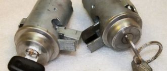
As mentioned above, practice shows that breakdowns are common to both parts of the lock and often require replacement of one or the other half. Sometimes VAZ 2106 ignition coils can fail
When servicing these elements, you need to know what a non-contact ignition circuit is, and after that you need to disconnect the negative terminal on the battery, except if you check the presence of voltage at consumers.
- Mechanical failure
The most common malfunction of the mechanical part of the locking system is a tight turn of the key; if the connection problem is not solved in time, the key will jam in the lock or break. As a result, you will have to change the entire lock, and such a replacement will require large expenses.
Factory ignition switches from VAZ 2106 cars very rarely break down in this way; such a malfunction is typical for Chinese spare parts, because the cost of the analogue is an order of magnitude lower. Analogs cannot be repaired, unlike spare parts from the LADA automobile plant.
Potential problems
Possible troubles are often related to the mechanical part. They are manifested in the following factors:
- the key fits tightly into the “secret”;
- it is not possible to make a turn the first time;
- It is problematic to remove the key from the cylinder, etc.
If you ignore such signals, it may result in breakdown. As a result, you will have to spend money on restoring the mechanism or replacing it.
In some cases, the use of special chemicals may help. One of them is WD-40 fluid. Brake fluid can replace it, which also helps delay repairs for a while.
In addition to mechanical breakdowns, motorists have problems with the electrical part . They manifest themselves in burning contacts or breaking the circuit. It is believed that the most vulnerable pinout of the VAZ-2107 ignition switch is at the starter connection terminals. In such a situation, no operation occurs either on the first attempt to turn, or on subsequent attempts.
Every motorist can test the functionality of the contacts independently by measuring the voltage on the contacts with a multimeter or voltmeter.
When faults are detected in the contact group, a complete replacement of the lock is not always required. It is enough to replace the electrical part of the lock even without completely dismantling the cylinder.
Ignition switch device
The design of the ignition switch depends on the car model. There are two types: with a key and without a key. When cars first began their development, their ignition locks did not have keys. Similar designs were used until the mid-twentieth century, and then they were replaced by conventional models that use a key.
Despite the fact that now there is a revival of push-button ignition locks, the most common type of design remains where the use of a key is required. The most convenient variation of the model is considered to be a flip key.
The design of ignition switches is similar for most passenger cars. The part consists of two main parts. The mechanical one has a cylinder into which the car owner inserts the ignition key. It provides protection against theft. The electrical one comes from the contact unit.
The key has a cylindrical lock, which is responsible for both turning the contact unit and locking the steering wheel. All parts are sequentially connected to each other.
Larva
The part is the part into which the key is inserted to select the desired circuit connection. It is installed in a cylindrical spring, one of the ends of which is fixed to the lock body. The cylinder lock assumes automatic return of the lock in case of unsuccessful start. The part is connected to the leash.
Leash
The part resembles a wide cylinder with a through channel. There are balls at the ends of the radial channel, and a spring is placed between them. The design of the part assumes that the spring allows the balls to fall into the holes on the lock body. Thus, the leash allows you to rotate the contact unit disk and also guarantees the lock’s fixation.
Contact node
The part consists of a contact disk with plates (through which current passes), as well as a stationary block. The last element has about six contacts with leads on the reverse side. Typically, contact plates with a single connector are used.
contact Group
This mechanism is one of the most important parts of the ignition switch, since it is the connecting link between all other components.
The mechanism closes the contacts of the electrical wires in the sequence required for a certain operating mode, which ensures the distribution of current between the devices of the machine. The position of the rotating parts of the contact group corresponds to the position of the key in the lock. The contact group is necessary for more convenient connection and grouping of vehicle electrical networks. The part is indispensable in terms of practicality: using a contact group saves the car owner time and money. The fact is that connecting all contacts directly is extremely inconvenient. If it was necessary to replace any element, the driver would have to climb into the lock body and separately solder each contact. The contact group solves this problem, and its replacement is cheaper.
The key circuit is closed while turning, and electricity rapidly moves from the negative terminal through the wire system, and then from the lock contacts to the induction coil. It generates additional voltage and transmits it to the spark plug. The current then returns to the positive terminal of the battery.
As a result of many years of friction, the elements of the group can wear down, which leads to overheating and burnt contacts. Due to such malfunctions, interruptions in the operation of a variety of vehicle systems are possible. Often, replacing a contact group successfully solves the problem of failure of several systems at once.
Changing the lock yourself
Knowing what is included in the circuit, which serves as an analogue of a crooked key, we can say that you can handle it. After all, the principle is completely simple. Therefore, if there are problems with the springs or core, you should always just open the cover and that’s it! The rest is very simple. You can replace either individual parts or the entire unit. The main thing to remember is that before the starter it was much more difficult, but the meaning of its functioning remained the same.
What could be the causes of breakdowns?
- The wires are worn out, which means the cable needs to be replaced.
- The contact in the connector circuit was broken, it was burnt and oxidized.
- The cylinder itself, where the key is inserted, has broken.
- The keys were lost, which happens most often.
It is for these four reasons that you will have to lift the panel cover and deal with the core, springs and wires. And this is a complex process. It requires close attention, knowledge and caution.
- First, you will need to disconnect the battery to avoid electrocution. To do this, remove the terminal that has a negative contact.
- Now remove the cover that is located below the steering wheel.
- You will also need to turn off all electrical appliances.
The lock is not that easy to unscrew. Once the cover has been removed, the hard part begins.
- Take a hammer or chisel and try to knock the lock out of its hole. Such bolts in the form of creases sit very tightly in their sockets.
- When the lock is replaced, it will be possible to put new bolts on the cover, which are easier to remove in case of a new need to replace the cylinder.
Removing a faulty device
We take out the lock and disconnect the wires from the terminals. It is very important that the connection remains unchanged. Press the latch and install the lock. Using a screwdriver, unscrew the 5 screws of the steering column switch housing.
The mechanical part is installed directly in the ignition switch itself. Alternately move the wires from the previous part, choosing the correct contacts. The design of the electronic ignition on a VAZ consists of two elements: The electrical part is a wire terminal fixed at the bottom of the lock with a locking clip. In this case, it is important to remember that the connection diagram plays a huge role, and you should not mix up the wires.
Therefore, the key closes the contacts of the ignition circuit, thereby starting the car engine. Place the steering column cover in place and secure the two parts together.
Factory pinout
According to established tradition, drivers are forced to insert the key into the “secret” located on the left side. Such design features may cause some inconvenience for some motorists who have switched from foreign cars to domestic “classics”.
The VAZ 2107 ignition switch circuit used in a car, an injector under the hood or a carburetor, will be similar. The unit is secured with two bolts to the steering column. The mechanism of the device is hidden under the plastic casing.
Each rotation angle involves the activation of certain electrical consumers connected to the on-board network. Before connecting the ignition switch to the VAZ-2107, you need to familiarize yourself with the marks located alternately around the cylinder:
- the starting position determines the inclusion of most systems and electrical consumers, which most often include “stops” located in the rear lights, interior lighting lamp, cigarette lighter contacts, and sometimes the radio is switched to this mode;
- “I” – second position; continuing to move to battery-dependent marks, demonstrates the inclusion of windshield washers, heaters, measuring instruments and control indicators, head optics, etc.;
- “II” – starting the power plant through the starter has its own peculiarities, since if the key is not forcibly held in this position, it will spring back to its previous position on its own, which allows minimizing any load on the electric motor;
- “III” is a parking position used by motorists when it is necessary to lock the column with latches, so when it is activated, the driver removes the key from the “secret”.