Car modifications 2115
VAZ-2115. The very first car that was produced since 1997. It was equipped with a 1.5-liter carburetor engine producing 76 horsepower. The maximum speed was 165 km/h, and the acceleration time from 0 to 100 km/h was 13.2 seconds.
VAZ-21150. The next modification, released in 1998, was equipped with a 1.5-liter carburetor engine producing 68 horsepower. was discontinued in 2000.
VAZ-2115-20. A modification of the car released in 2000, equipped with a 1.5-liter VAZ-2111 injection engine with a power of 77.8 horsepower. The maximum speed was 170 km/h, and the acceleration time from 0 to 100 km/h was 14 seconds.
VAZ-2115-40. A modification with a 1.6-liter injection engine, which has been produced since 2003. The car's maximum speed was 158 km/h, and the acceleration time to 100 km/h took 13.2 seconds.
VAZ-2115-91. A car with a 1.3-liter Wankel rotary piston engine producing 135 horsepower. The maximum speed is 190 km/h, and the acceleration time to 100 km/h is 9 seconds.
VAZ-21154. The latest modification of the car with a new VAZ-11183 engine with a volume of 1596 cm3 and a power of 81 horsepower. Produced since 2007. The maximum speed and acceleration time to 100 km/h are exactly the same as that of the VAZ-2115-40.
Electrical diagram of VAZ-2115-01
Years of production 2115: 1997—2012. This is a circuit with a regular button for rear fog lights (with locking), a fluorescent interior light, a connector for the clock and an 8-pin connector for the injector wiring.
1 — block headlights; 2 — fog lights; 3 — air temperature sensor; 4 - generator; 5 — electric motor of the engine cooling system fan; 6 — fan motor activation sensor; 7 — engine compartment lamp switch; 8 — block for connection to a single-wire type audio signal; 9 — sound signal; 10 — oil level sensor; 11 — front brake pad wear sensors; 12 — washer fluid level sensor; 13 — spark plugs; 14 — ignition distributor sensor; 15 - switch; 16 — carburetor solenoid valve control unit; 17 — carburetor solenoid valve; 18 — carburetor limit switch; 19 — speed sensor; 20 - starter; 21 - battery; 22 — relay for turning on fog lights; 23 — coolant level sensor; 24 — brake fluid level sensor; 25 — reverse light switch; 26 — coolant temperature indicator sensor; 27 — engine compartment lamp; 28 — windshield wiper gearmotor; 29 — oil pressure warning lamp sensor; 30 — block for connecting to the rear window washer electric motor; 31 — electric motor for windshield washer; 32 — ignition coil; 33 — instrument cluster; 34 — mounting block; 35 — brake light switch; 36 — blocks connected to the injection system wiring harness; 37 — ignition switch unloading relay; 38 — ignition switch; 39 — glove box lighting lamp; 40 — switch for the glove compartment lighting lamp; 41 — rear window heating switch; 42 — fog light switch; 43 — fog light switch; 44 — external lighting switch; 45 — alarm switch; 46 — steering column switch; 47 — instrument lighting regulator; 48 — hydraulic corrector scale illumination lamp; 49 — socket for a portable lamp; 50 — side direction indicators; 51 — switches in the front door pillars; 52 — lamp for individual interior lighting; 53 — electric heater fan; 54 — additional resistor of the electric heater fan; 55 — heater electric fan switch; 56 — backlight lamp for the electric heater fan switch; 57 — backlight lamp for heater control levers; 58 — display unit of the on-board control system; 59 — trip computer; 60 — switches in the rear door pillars; 61 — block for connection to the clock; 62 — electric fuel pump with fuel level sensor; 63 — ashtray lighting lamp; 64 — cigarette lighter; 65 — trunk lighting; 66 — trunk light switch; 67 — interior lamp; 68 — parking brake warning lamp switch; 69 — external rear lights; 70 — internal rear lights; 71 — plugs for connecting to the rear window heating element; 72 — license plate lights; 73 - additional brake signal.
See the complete diagram in one file below (click to enlarge):
Circuit 2115 with “high” panel 21083 is similar to circuit 21099 (except for the rear harness).
Circuit breakers
F1 (10 A) - rear fog lights, their activation lamp on the panel. Headlight cleaner motors (turn on). Headlight washer motor. If your rear fog lamps do not work, check the button to turn them on. When connecting a PTF, a fuse is usually installed, which is located directly on the wire behind the button. Check it out. Check the lamps. The PTF lights only when the low beam is on; this should be taken into account when searching for the cause.
If the headlight cleaner or washer does not work, see the information about relay K1, and also check the fluid level in the washer reservoir and its pump.
F2 (10 A) - turn signals, their relay-breaker and hazard warning lights. Hazard warning light. See information about relay K2, the main problems and solutions are described there.
F3 (7.5 A) - interior lighting.
Individual light lamps. Trunk lamp. Illumination of the ignition switch. Check engine lamp. Stop lights. Trip computer, clock.
If your brake lights stop working, check the fuse, although it is unlikely to be the problem. In models VAZ-2114, VAZ-2115, rear lamps are a disease. The problem is the board on which the lamps are installed. The solution is to replace this board with a new one, in this case it is not known how long the new one will work. The simplest solution is to solder the wires to the lamps directly, or replace the connectors with connectors from another VAZ model, for example 2106.
If it's not the circuit board, check the brake light switch (frog) located by the brake pedal. This can only be the case if none of the brake lights are on, even on the spoiler. If the signal on the spoiler is on, but the others are not on, the problem is most likely in the rear light board. Also check the chips that connect to this board and their contacts. If these connectors fail, they must be replaced or the contacts inside them must be bent.
The VAZ-2114 model has two brake light lamps, the VAZ-2115 model has four. The lamps themselves may also fail individually, you just may not notice it. In some cases, it may be the wiring under the dashboard. If you don’t understand electrics, contact a car service center; most of them have long learned to deal with such problems and it will not be difficult for the technician to find the fault.
F4 (20 A) - portable lamp. Heated rear window. See information about relay K7.
F5 (20 A) - sound signal.
Radiator cooling fan. For the sound signal, see the information about relay K6. If the fan does not work, first check the functionality of its motor. To do this, connect it directly to the battery. The fan should be spinning. If it works, check the coolant temperature sensor and its contacts. It might be the thermostat. Do not allow the engine to overheat by more than 100 degrees.
If the sensor is faulty, or a different type of sensor is installed, the arrow on the dashboard may show an incorrect temperature. Overheating is accompanied by boiling, bubbling or the release of vapors from under the coolant expansion tank cap.
The reason may be in the electronic control unit and in the temperature settings for turning the fan on and off. When the wires from the sensor on the upper pipe are disconnected and the ignition is on, the fan should work. This indicates the health of the electrical circuit. Also check the wiring that comes from the fan and all connectors. The wires could rub against the body, and the contacts in the connectors could melt or oxidize.
F6 (30 A) - electric windows. See information about relay K5.
F7 (30 A) - stove motor.
Windshield washer and headlight cleaner motors (in their operating mode). Cigarette lighter. Glove compartment lamp. Heated rear window (winding). Heater problems. If the stove operates only at the 3rd speed, and does not turn on at the first two, most likely the additional resistor through which voltage is supplied to the stove motor has burned out, or the contact on its connector has lost. The resistor is located above the gas pedal and looks like a plate.
If the stove does not work in any of the positions, check the switch itself on the panel and its contacts; the stove motor may also have burned out or its brushes may have worn out. To measure the voltage, look at the wiring or change the heater motor, you need to unscrew the heater fan casing, which is located under the hood. When installing a new motor, there may not be enough space to fit the entire motor into place. In this case, try either placing it sideways and then turning it, or first disassemble it into 2 parts and then assemble it in place. A new assembled motor costs about 800-1000 rubles.
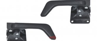
Adjusting the handles
When repairing a VAZ 2114 and adjusting the door handle, you will need a 20mm screwdriver from your inventory. Disassembling the device will correct the incorrect service of this element. Step-by-step instruction:
- Remove the plug.
- Unscrewing the bolts.
- Handle recess.
- Disconnecting the retainer wires.
- Checking the mechanism.
If improper operation is caused by blockage, then the internal elements are cleaned and lubricating work is carried out. When assembling the device, do not tighten the screws too much, no more than four turns with a screwdriver.
Replacing the ignition switch on VAZ 2114 and 2115. Work in the evening
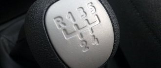
- A set of keys. Both ordinary keys and heads should fit into it;
- Phillips and slotted screwdrivers;
- Pliers;
- Thin chisel;
- Hammer.
- You should start by removing the steering wheel. To do this, use a slotted screwdriver to pry up and remove the trim with the inscription LADA (in some cases Lada). This will give you access to the 4 screws securing the steering wheel cover. Unscrew all the screws and remove the cover;
- Slightly unscrew the nut securing the steering wheel. Don’t unscrew it completely right away;
- We tear the steering wheel off the splines. With all this, it requires quite a huge amount of effort. To avoid damage, leave a nut that is not completely unscrewed as a limiter;
- Next, you should unscrew the nut one hundred percent and remove the steering wheel from the car;
- Remove the plastic casing from the control column using a Phillips screwdriver;
- Turn the key to position I, this will remove the lock from the groove, and you will not have any problems when removing the unit;
- To remove the ignition switch, you need to unscrew the bolts that secure it. This is where a little difficulty arises. For greater reliability and security, the bolt heads break off when installing the lock. To turn them out, you need to use a narrow chisel. It is placed on the head of the bolt and, applying light blows with a hammer, we unscrew the fastener. As soon as you can unscrew the bolt a little, finish the job using pliers. They do the same with the rest;
- The old lock is being removed. If desired, it can be restored;
- A new or repaired lock is installed in place. With all this, be sure to make sure that the tongue blocking the steering wheel is in the correct position. Before installation, it should be recessed into the groove of the lock;
- Tighten the screws securing the lock. Their heads are designed like typical torque wrenches. When the tightening reaches the required torque, the head simply breaks off. Thus, the bolts are disposable. They are usually sold together with a lock or in separate repair kits;
- A block with wires is connected to the contact group;
- All removed parts are installed in place.
Disconnection Guide
Do I need to turn off the immo or alarm and how to do it correctly? We invite you to take a closer look at these issues.
Is it necessary to disable the immobilizer on the fourteenth VAZ model?
If there is a need, then of course it is necessary. The need to turn off the alarm or immobilizer arises in cases where the system blocks engine operation and starting the power unit becomes impossible.
How to disable?
If we are talking about signaling, then first of all you need to know about the connection points that were used during installation. Every anti-theft system has an emergency stop button, usually called the Valet service button.
It doesn’t matter whether it’s a European emergency warning button for a VAZ 2114, a new model or an old one
The combination with the use of Euro emergency lights in the event of the anti-theft system being disabled is described in the operating manual. This process is individual for each individual signaling model, so we will not describe it. If the emergency lights on the “four” do not work, then you will have to turn off the central unit, but you cannot do without the help of a professional in this matter.
As for how to properly disable immo with your own hands, the procedure is as follows:
- First you need to find the block of the installed anti-theft system. If you installed the immobilizer yourself, you should know where the control module is located. If the installation is installed from the factory, then the module should be located inside the dashboard, directly under the steering wheel.
- Next, you need to disconnect the connector with the signal wires from the control module. Disconnect the wires and move them aside.
- Now you will need to find pins numbered 9 and 18, for a total of 20 pins on the connector.
- Contacts numbered 9 and 18 must be cut using a utility knife. Strip the contacts of the cut wires, then twist them as securely as possible and insulate them. Use electrical tape to insulate the section. By completing these steps, you can restore the K-Line diagnostic line, which will allow you to monitor the condition of the main systems and components of the vehicle.
- Next, reinstall the connector. This way you can disable the anti-theft system and start the engine. This method is the simplest, but it must be borne in mind that it does not guarantee the correct disabling of the anti-theft system.
Photo gallery “Reflashing the control unit”
A more complex, but more effective option is to reflash the control unit. To implement it, you will need a soldering iron, a computer with a flashing utility, and a board programmer.
Flashing is carried out as follows:
- First, the control module is removed from the car.
- Next, the cover of the device is opened.
- Now you need to find a board with immo data written on it. If your car uses the January control unit version 7.x, then the circuit designation is 24С04.
- Next, you have two options for solving the problem - you either install a new circuit, or you will clean the old one. To perform the cleaning, you will need a computer or laptop with a Windows operating system, as well as an appropriate memory cleaning utility. There are many programs on the Internet, you can select software for a specific ECU model.
- The next step will be to desolder the circuit using a soldering iron, as well as install a new board. Well, or you reflash the circuit, whatever. If we are talking about firmware, then with the help of a properly configured utility you can complete this task in just a few minutes.
- When the process is completed, all you have to do is solder back the new board and check the functionality of the system.
Sources
- avtozam.com/vaz/2114/vklyuchenie-i-otklyuchenie-immobilajzera/
- drive2.ru/b/2094661/
- ladaautos.ru/vaz-2114/kak-samomu-otklyuchit-immobilajzer-na-vaz-2114.html
Installation instructions for central locking
Before installing the central locking system, you should study the connection diagram
Photo gallery “Central locking diagrams”
1. Central locking diagram for VAZ 2114
2. Central locking diagram
3. Connection diagram of the central locking system to the alarm system
The central locking control module is located on the left side under the panel. There are 6 wires coming from it. To install the central locking system, you need to disconnect the brown and blue wires.
Before connecting, you need to check that activators with 5 outputs are installed in the doors. If they are missing, they should be installed.
In a car, the one responsible for opening the doors is usually white and connected to terminal 7. If there is no connection to terminals 7 - 5, then the 8th terminal is connected to the brown wire. This wire is responsible for opening the doors. Terminals 5 and 6 are for closing doors.
To install the central locking system, you must purchase additional items:
- 2-3 diodes 1N4001 at 1A;
- one diode 1N5401 3 A;
- 2 diodes of 4 or 5 A, if there are no separate outputs for turn signals.
The central locking VAZ 2114 (hereinafter referred to as CZ) is a mechanism that ensures the simultaneous closing or opening of all four doors in the car. This option is very convenient; it eliminates the need to reach out and lock the doors manually every time. Such centralized control comes in handy when installing car alarm systems, which significantly expands the possibilities and variations of the use of the locking mechanism.
The operation of the lock itself does not depend on whether the car engine is running or the fact that the ignition is turned on. Power is supplied directly from the battery. It is quite common for the system to malfunction. For example, when the locks of some doors close, but the rest do not. Or the closing process occurs with great difficulty, jamming, or partial failure of the latches. A situation familiar to many car enthusiasts, isn’t it? There are several reasons for the node to not work correctly; we will look at them in more detail.
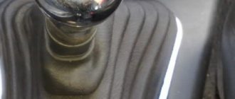
How to Replace the Ignition Switch on a VAZ 2115
It is impossible to start the engine, its systems and other main devices of the Samara family without the ignition key. Those motorists who have encountered a malfunction of this device know what causes its sudden breakdown. Particularly if it becomes a pass.
Further in the text of the article we will talk about what the VAZ-2114 ignition switch is, consider its main malfunctions and ways to eliminate them. In addition, we will try to figure out how to change this ourselves and connect correctly.
In VAZ-2114 cars, the ignition switch, unlike the “classic” one, is located not on the dashboard, but on the right, on the control column. The top is covered with a plastic shell, so in our opinion only the highest part of the “larva” is exposed.
The VAZ-2114 ignition switch consists of 5 main parts:
- iron body;
- locking mechanism;
- blocking device;
- contact Group;
- key.
The device is housed in a metal case, which is designed to protect against burglary. As for the locking mechanism, it is practically no different from a regular door lock.
The locking device allows you to lock the control shaft in the absence of a key. In this simple way, it protects the car from theft. The contact group is the element responsible for starting the engine and its systems. The VAZ-2114 ignition key is used to unlock the locking device and activate a group of contacts. Without it, starting the engine makes it impossible to disassemble the device.
This is how the lock works. When the key is in the well, its locking mechanism is disabled. This is due to the reverse movement of a special rod. Turning the key to position 1 will give contacts “15” and “30”. This will prevent (unfortunately, not enable) the following:
- ignition system;
- headlights;
- external light signal;
- electrical equipment of the dashboard;
- windshield washers and washers;
- lighter;
- heated rear window;
- field generator winding.
In this case, turn the ignition key to position 2 in the VAZ-2114, in addition to the listed equipment, the starter will start. As you can see, a lot depends on the performance of the device.
What are the symptoms of a broken ignition switch? The first issue is that its failure can be either mechanical or electronic. At the beginning it is:
- lock jamming in one of the positions;
- inability to unlock the control shaft;
- turning on the ignition with a non-original key in accordance with another object.
If you have electronic faults, you can easily see the following symptoms:
How the central lock works
Central locking is a system that, when given a certain command, performs the function of opening or closing an object. For ease of use, this operation is performed remotely. Some car enthusiasts choose the function of closing all doors after a certain period of time. It is very convenient for those cases when the driver does not have time or forgets to close the car door. As a rule, using a long-range remote control you can control both the trunk and the hood, close and open the windows. The most common way to control the remote control is by pressing one button, after which all the locks on the car are activated. If the remote control does not work for some reason, then you need to insert the key into the door lock and turn it clockwise. If an accident occurs, the car's security system is activated automatically and all locks open. At the heart of the central locking mechanism are incoming sensors located in the structure itself. These are microswitches and door switches (limit switches), actuators and a control unit. The limit switch must maintain the door position and this information must be transmitted to the control unit. The switches fix the structural part of the door lock. The front doors of the car are equipped with a cam device. To fix the cam, the front doors are equipped with microswitches: there are two parts for each mechanism. Blocking the lock is formed by one switch, and unlocking is formed by the second. There are two more microswitches used by the central locking mechanism. A fifth switch is installed on the lever device in the lock drive. It serves to determine the door position: when the door is open, the switch contacts close and the central locking system is deactivated. The electronic mechanism (unit) receives the signal from the microswitches and sends information to the central control. In order to open an object, the central device sends a signal to certain control units, thereby activating the mechanisms in the locks.
Causes of malfunctions
The fan may not turn on for the following reasons:
- the fan drive (electric motor) is faulty;
- fuse is blown;
- the relay has failed;
- broken electrical wiring;
- lack of contact in the temperature sensor connector;
- The temperature sensor is faulty.
Search for reasons
Diagnosis of a fan malfunction should begin with the fan itself. To do this, disconnect the connector on the fan and connect it, observing the polarity, directly to the battery terminals. If it turns on, it means the drive is working, the reason needs to be looked for further. If the fan does not work, this is the reason. But let's take things in order.
The fan did not turn on. We check the integrity of the wiring and the condition of the contacts on the sensor. If everything is in order, we move on to the fuse and fan relay. They are located under the hood on the left side closer to the driver, in the mounting block.
Fuse F4 is 20A, double, for the sound signal and the cooling fan (it is very easy to check; if there is no sound signal and the fan does not work, then most likely it is the culprit).
You can check the fuse with an ordinary autotester. With relays the situation is more complicated. To make sure that this is not the case, it is better to get a one hundred percent working relay somewhere and temporarily install it in the socket for testing. If the fan does not work even with it, we go to the sensor.
If the sensor is de-energized, the controller must start the fan in emergency mode for constant blowing. Disconnect the connector from it and turn on the ignition. Turning on the fan will indicate that the sensor has failed and requires replacement.
When is it necessary to change a fan?
If the cause is still in the fan itself, you can try to repair it. The problem is usually the brushes or bearings. But it also happens that the electric motor fails due to a short circuit or break in the windings. In such cases, it is better not to experiment and replace the entire drive.
It is strictly forbidden to operate a vehicle with a non-working cooling fan. Overheating of the coolant will inevitably lead to the destruction of rubber pipes and hoses, as well as cylinder head gaskets and valve covers. In addition, high engine temperature can cause destruction of the piston group elements.
Central locking diagram for VAZ 2114
The system consists of the following components:
- mounting block;
- 8 amp fuse;
- 4 gearmotors (one in each door, and the one in the driver's door has a contact group);
- central locking control unit;
- wires (red, black, blue, yellow) and plugs;
- rods that are located in each door;
- limit switches that signal the current state of the door (open or closed).
Troubleshooting
Below are examples of how to fix basic problems and how to easily find them.
Fuse
This is the most frequently damaged element in brake light failures, and also the most easily repaired. To eliminate the breakdown, you just need to replace the fuse on the mounting block.
The fuse responsible for the operation of the VAZ 2114 brake lights is located on the fuse block under number F3 and has a fuse-link current of 10A.
To make sure that the fuse has blown, you need to turn on the interior lighting. If the brake light fuse is faulty, the light in the car interior will not light up because This fuse F3 is responsible for lighting the interior and the on-board computer.
Below is a diagram of the VAZ 2114 fuse box.
Brake pedal sensor
The brake pedal switch is responsible for turning on the brake lights when you press the brake pedal. This sensor is located on the pedal assembly of the car and is a kind of limit switch. When you press the brake pedal, the contacts on the sensors close the power supply circuit of the brake lights and light up their lamps, signaling that the car is braking.
Quite often, the spring that pushes the contacts to close on this sensor breaks, thus the sensor does not close the contacts when the brake pedal is pressed and the brake lights do not light up.
Replacement is carried out using a set of keys.
Lamp burnout
Often, the culprit of brake light malfunction is burnt-out lamps, but it should be noted that the likelihood of two lamps burning out at the same time is very small. Most often, when a brake light bulb burns out, one light fails.
The lamps are replaced from the luggage compartment of the car.
The type of lamp installed in the rear brake light of the VAZ 2144 is P21W – 12V.
Cartridge oxidation
Over time, due to moisture, the contact on the socket into which the light bulb is inserted can oxidize and the contact between the socket and the light bulb will disappear, which will make it impossible for electric current to pass to the lamp, thereby making it impossible to light it.
This problem can be eliminated by cleaning the contact using sandpaper and the lamp contact.
Connector oxidation
Just as with oxidation of the cartridge, due to exposure to moisture, the contacts on the connector oxidize, thereby blocking the path of electric current to the lamp. With such a breakdown, most often the entire lamp suffers and not only the brake light stops lighting, but also the turn signal, clearance signal, and reverse signal.
The problem is eliminated by cleaning the contact with sandpaper and treating with alcohol.
Damage to the board
This problem is less common, but it causes damage to the flashlight. The board is a plate of conductors to which a connector is connected. Conductors are tracks that quite often fray or break, which leads to an open circuit and, consequently, to failure of the lantern.
Solving this problem is quite problematic; it is necessary to solder the soldering iron tracks. Most often, when such a breakdown occurs, the flashlight is completely replaced.
Broken wire
A broken power cord is the most common problem. Most often, a break occurs in the luggage compartment of a car due to loading and unloading of various cargoes that can break this wire.
The most difficult thing in this problem is to find the break point. It is necessary to carefully inspect the places where the wires are laid in the luggage compartment.
We hope our article was useful to you.
Repairing partial failures of the vacuum central locking system
Most often, malfunctions occur that are accompanied by prolonged operation of the compressor (for 15–20 s or longer until its protection is triggered):
- The central locking opens and closes the car doors (and vice versa) until the pump turns off.
- All the doors opened/closed or the lock did not work on some (possibly uneven operation of the locks), and the compressor continues to hum until the protection turns it off.
The reason for the 1st case may be: a malfunction or “floating” due to condensation or other reasons; the contact of the driver’s door actuator switch - voltage is supplied from the drive via both control wires to the pump board (“plus” for both opening and closing - in As a result, the compressor either pumps air or pumps it out). It is necessary to inspect the switch and, if necessary, repair or replace it.
- Leakage of vacuum line tubes.
- From the limit switch of the actuator of one (or several) of the doors, the signal that the lock has closed/opened does not reach the compressor operation control board, and the pump continues to circulate air.
- Signals about locking/unlocking the locks come to the compressor board, but it “ignores” them.
In the first case, first check the line to the door with a non-operating drive. The damaged area can be identified by the hissing of air. Broken tubes are replaced. If all the hoses are intact, then one of the drives is leaking - usually the membrane in them is torn or cracked. If there is no suitable membrane or used actuator, you will have to purchase an assembled door lock.
In the second case, the repair begins with checking the electrical circuits from the door actuators to the control board for the presence of voltage on the corresponding wire. You can simply compare the state of all circuits from all drives. Most likely, the incorrect signal is coming from only one drive, and the voltage measurements on the wires of the bundle coming from it will be different from the readings on the wires from all the others. Then you should find the open circuit and repair it. Most often, damage occurs in the door corrugations. If the wires are intact, then the reason lies in a faulty limit switch, which is being repaired or replaced.
In the latter case, it is necessary to disassemble the compressor unit and clean the contacts of the opening/closing alarm pneumatic sensor terminals - most likely, they have oxidized. If this does not help, then you need to check the control board circuit - it needs repairs.
Causes of car alarm malfunction
Every motorist should know how to turn off a car alarm. In fact, there are several options for solving this problem, and we will tell you about some of them in this material. First, let's look at the reasons why the alarm system refuses to work:
- Radio interference. The metropolis is an area of increased air pollution. Large enterprises, parking lots, mobile operators and reinforced concrete structures all interfere with security systems. You can try to turn off the alarm by reducing the distance from the key fob to the transmitter in the car. Bring the key fob to the place where the receiver or antenna is installed.
- Battery If the battery is faulty, it may lose charge while driving. You must first check the battery by turning on the ignition and looking at the instrument panel. If they don't work, it's probably due to a dead battery. In this case, turning off the alarm is limited to turning off the siren, after which you need to charge the battery.
- Batteries in the key fob. Make sure the batteries inside the key fob are working properly. On devices with one-way communication, when you press any button, the indicator lights up. Otherwise, replace the battery. On key fobs for two-way alarms, the display usually has a battery charging indicator. If there is no place to buy a battery nearby, you can revive it for a short time. Remove the battery from the key fob and tap it, trying to deform it slightly. This way you can turn off the alarm and get to the place where they sell batteries.
Installation of central locking
When purchasing a VAZ car from a specialized car dealership, there is a possibility that the functionality of the basic security system will be limited.
That is, only doors (sometimes not even all) can be locked with a remote control or key. For car safety, drivers install alarms on all opening parts of the car. To do this, you can use the services of specialists from a service station, or you can do the installation yourself. If you know the circuits of the central locking and the operation of the electronic device itself, then you can easily install a lock on any part of the car. Specialists of various levels use instructions when installing an alarm system on a car. VAZ 2114 central locking diagrams and security system installation rules are included with the alarm system. Despite the fact that such a simple but important system as central locking can fail, you will not meet a driver who would not praise it. When purchasing a car, everyone looks at the package, which should include an electric alarm system (or central locking). Many cars do not have an alarm system, but have central locking, which was installed at the factory. There is no big difference, but the convenience of the presence of a centralized blocking system is appreciated. This is better than waiting for passengers to get out of the car, then closing all the doors from the inside and closing your own when exiting. It is convenient to press one button on the control panel so that all doors close/open at once. A problem with the system is possible when the battery in the key is dead. But this is not a very serious “trouble”, which can be solved by simply replacing the power source. The central locking diagram clearly proves the simplicity and uniqueness of the device.
The device of the standard immobilizer APS-4
First, let's figure out what this immobilizer model is and what functions it does. This kind of device is designed to prevent your car’s engine from starting in cases where access to it is recognized by the system as unauthorized, in other words, in the event of a possible theft.
This can lead to a complete replacement of control and monitoring units in the event of defects. When the ignition is turned off, the immobilizer is activated automatically (the buzzer will emit a small sound signal, and the indicator will go into flashing mode every 2.5 seconds), switching to the theft protection mode.
Repair features
If the VAZ 2114 central locking does not work, then it is necessary to carry out diagnostics and find the cause of the breakdown.
Then carry out the appropriate repairs. Difficulties with central locking on the VAZ 2114 in most cases appear at low temperatures and high humidity. The prerequisites are locks with solenoids, which are installed from the factory. It is better to replace them with locks with an electric motor.
If the drive is not working on only one door, you need to check its electrical circuit for an open circuit using the dialing method. In most cases, broken wires are located in the corrugation. Because doors are often opened and locked, the insulation cannot withstand the load. The break is restored by replacing the wire and connecting the broken sections using female-male terminals.
If there is no break, the reason may be a failure of the control board or the turn-on relay. The winding of the motor or solenoid may burn out, and the drive gears may wear out. In this case, it may be necessary to change the auxiliary door drive.
How the central lock works
The operation algorithm of the central locking system consists of sending a pulse to the VAZ 2114, in which the received signal is analyzed and commands are generated that control the door locks. They are either opened or locked.
General scheme of central locking
Elements that activate the central locking are connected to pin 30. If contact 87 closes, then the activator outputs will be affected by ground. When a certain relay 30 is activated, the contact will connect to the positive. Thus, the activator will receive power and the rod will begin to move. The control unit rod closes different pairs of signals depending on what action needs to be performed: closing or opening the doors.
Since the central locking activators are connected in parallel, all doors will either open or lock at the same time. Central locking can be pneumatic or electric. The first type of device includes a control panel, compressor and tubes. In an electric one, the main element is a motor, thanks to which the mechanisms are activated.
What do the tidy indicators do?
The control panel on the VAZ 2115 is located in the center console directly in front of the driver.
Descriptions of instrument cluster symbols are given below:
- Coolant temperature sensor, if the controller arrow moves into the red zone, this indicates that the power unit is overheating.
- A tachometer informs the driver about the crankshaft rotation speed; if the arrow falls into the red zone, it is necessary to reduce the engine speed.
- Left turn signal.
- Right turn signal.
- A speedometer that tells you how fast a vehicle is moving.
- Fuel level sensor in the tank.
- The light indicator, made in the form of a gas pump, usually lights up if there is no more than 7 liters of fuel left in the gas tank.
- Optics indicator, activated when the side lights are turned on.
- In accordance with the instructions, an indicator in the form of an exclamation mark lights up on the instrument panel if the brake fluid level has dropped and reached a minimum.
- High beam activation indicator light.
- This is a button designed to reset the daily mileage on the odometer and set the clock.
- An odometer that records the mileage of a vehicle.
- Light alarm, when turned on, this indicator will blink.
- The icons include one important indicator - Check Engine. This symbol always flashes when the engine starts, but disappears after it starts. The indicator may appear if the control unit detects certain problems in the operation of the power unit.
- The display showing the outside temperature and time is switched using button 11.
- The battery icon appears when the ignition is turned on; if it is constantly on, then most likely the on-board computer has detected problems related to the battery charge. But if it occurs, the problem may also be caused by a malfunction of the generator, loosening of the strap, or breakdown of the unit.
- The letter P in a circle - the indicator appears when the car is setting the parking brake.
- This symbol lights up when the engine fluid pressure is too low.
- Reserve indicator (the author of the video about tuning the control panel at home is the Studio Pandora channel).
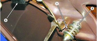
Correct adjustment of locks
To make the adjustment correctly, you need to know the action plan step by step:
- Lighten the tension of the bolts that secure the door lock.
- It will be good if you use a pencil to mark the contours of the retainer on the body pillar.
- The direction of shift of the latch is based on the situation: if the door closes too tightly, then it is moved outward, inward - if the door closes weakly.
- Vertical regulation occurs according to a simple relationship: if the door goes down, then the latch needs to be moved up, if the door goes up, then the latch needs to be released.