04.03.2022 52 198 VAZ 2107
Author: Ivan Baranov
The VAZ 2107 fuse box is a unit in which all safety components of the electrical network are concentrated. They are used to protect electrical equipment from power surges, so their performance is important for any car. You can learn more about the location and replacement of components from this material.
[Hide]
Mounting fuse block for VAZ 2107
The mounting block is an important element of the electrical circuit, since it contains some of the electrical control elements of the VAZ 2107 car, and most of the fuses that protect the main electrical circuits from short circuits and overloads.
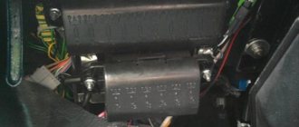
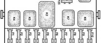
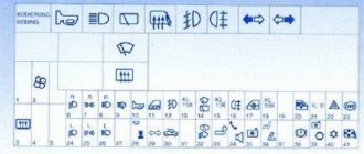
It is located in the engine compartment on the left side, directly on the metal partition between the engine compartment and the cabin. Therefore, replacing a burnt-out insert requires stopping the car. The photo shows the layout of all elements of the mounting block: relay for controlling electrical and electronic elements; fuses. It should be noted that the VAZ 2107 uses fuses of standard ratings that differ in color: the 7.5A rating is indicated in brown; 10A is distinguished by red; 15A blue; 20A is made yellow. Color-coded fuses make replacing fuses much easier. Diagram of mounting block elements
Numbers from 1 to 6 indicate relays or connectors for their installation:
- Rear window defroster control.
- Control of electric wipers and headlight washer motor (if equipped).
- Control of sound signals (a plug is installed instead of a relay).
- Connector for installing a fan motor control relay designed to cool the radiator (not used in new VAZ 2107 models).
- Control of high beam headlights.
- Control of low beam electric lamps.
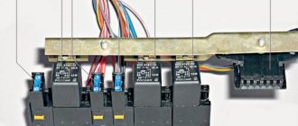
In addition, inside the mounting block there are special tweezers with which relays and fuses are replaced. It is very convenient to have them on hand, next to the replacement parts. The rest of the space is occupied by protective fusible links, indicated in the photo by numbers from 1 to 17, with the letter F in front. Below is a diagram of the mounting block fuses and a list of the circuits they protect. This is also true for the old-style mounting block. Thanks to the new relay design, replacing them is also not difficult.
| № | What protects | Rated current |
| 1 | Protects circuits: lamps in reversing lights; stove fan; heater (on indicator lamp and control relay), washer pump and rear window wiper. | 10 |
| 2 | Windshield wiper protection. | 10 |
| 3 | In reserve | |
| 4 | In reserve | |
| 5 | Electric rear window heater. | 20 |
| 6 | Cigarette lighter circuits, connector for turning on a portable lamp, clock on the dashboard. | 10 |
| 7 | Cooling fan and signal fuse. | 20 |
| 8 | Control circuits for turn signals in emergency mode. | 10 |
| 9 | Protection of fog light circuits and generator voltage relays for a number of VAZ models. | 10 |
| 10 | Dashboard warning lights. | 10 |
| 11 | Circuits for turning on the stop lamps. | 10 |
| 12 | Right high beam headlight circuits. | 10 |
| 13 | Protection of the left high beam headlight and warning lamp. | 10 |
| 14 | Protection of the side light circuits of the headlights (front left and rear right), rear license plate lighting, engine compartment lighting lamps. | 10 |
| 15 | Protection of the side light circuits of headlights (front right and rear left), lighting of the cigarette lighter socket, glove compartment. | 10 |
| 16 | Right low beam headlights. | 10 |
| 17 | Left low beam headlight lamp. | 10 |
The connection diagram for the mounting block connectors, indicating fuse numbers, wire colors and other useful information, is shown in the following figure:
The advantage of the new fuses used in the VAZ 2107 injector is that, unlike similar old-style inserts, they do not suffer from loss of contact due to a loose connector. The condition of the fuse link is clearly visible through the window at the top of the fuse. Replacement of fuses is carried out using special tweezers, which were mentioned above. If it is not there, replacement is carried out using small pliers, since pulling them out manually is extremely problematic.
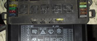
The arrangement of elements of the old-style mounting block is as follows:
The complete schematic diagram of the electrical equipment of the new VAZ 2107 (injector) is as follows:
This diagram will make it easy to figure out how to connect certain elements of the VAZ 2107, even without special skills. In the center of the diagram there is a mounting block from which all other elements are connected. It should be noted that for older cars the circuit diagram is somewhat different.
To avoid unpleasant situations associated with blown fuses on the road, it is strongly recommended to carry a spare set with you. Car enthusiasts know that VAZ 2107 cars, as well as other earlier models, suffer from unreasonable burnout of fusible protective inserts.
If you find an error, please select a piece of text and press Ctrl+Enter.
Device
When installing this engine, a large number of additional electrical circuits appeared, which became a prerequisite for installing the mounting block. Also, this could not but affect the fuse box.
Let's look at it one by one: “what is a mounting block, and why is it installed on an injector-type engine?” This device is used to store electrical control elements of the VAZ 2107 engine and protect them using internal fuses.
The location of this block is located on the partition, between the engine compartment and the car interior. Its diagram provides for the presence of relays for controlling individual elements of the system, connectors for connecting the elements themselves, and fuses of a standard type, which have different colors, which help determine the maximum permissible voltage on it. Thanks to this method, replacing fuses becomes easier and faster.
The mounting block includes 6 control systems, which are united by one circuit:
- The first system is heated rear window;
- The second is the electric motors for the headlight and windshield cleaner;
- The third is the control of sound signals (the block diagram of the VAZ 2107 car, instead of this relay, has a special plug);
- The fourth system is a fan responsible for cooling the radiator;
- Fifth - low beam;
- Sixth – high beam.
The factory version of the unit has special tweezers. With its help, you can easily remove any relay from its contacts and remove the necessary fuses. The mounting block of a VAZ 2107 car, with an injector engine type, has more modern fuses that do not stop working, even with a loose contact.
On the cover of the modern block, a diagram of the connection of all elements is drawn. This way, it will be impossible to make a mistake.
Purpose of VAZ 2107 fuses
The essence of the operation of fuses is that when the current passing through them exceeds, the insert located inside burns out, thereby preventing heating, melting and fire of the wiring. If an element has become unusable, it must be found and replaced with a new one. How to do this and in what sequence you need to understand in more detail.
Fuse box VAZ 2107 injector and carburetor
When operating a VAZ Seven, owners sometimes encounter a situation where one or another fuse blows. In this case, every car enthusiast should know and navigate where the fuse block (FB) is installed and which electrical circuit this or that element protects.
Where is it located?
The fuse box on the VAZ 2107, regardless of the engine power system, is located under the hood on the right side opposite the passenger seat. The unit has two versions - old and new, so in order to clarify the situation, it is worthwhile to dwell on each of them in more detail.
The choice of power supply sample does not depend on the vehicle's power system.
Old version of the block
The old mounting block consists of 17 protective elements and 6 electromagnetic type relays. The number of switching elements may vary depending on the vehicle configuration. Fuse links are arranged in one row, made in the shape of a cylinder, and are held using spring-loaded contacts. With this connection method, the reliability of the contacts is quite low, since at the moment large currents pass through the protective element, not only does it heat up, but also the spring contacts themselves. The latter become deformed over time, which leads to the need to remove fuses and clean oxidized contacts.
The mounting block is made in the form of two printed circuit boards, which are installed one above the other and connected via jumpers. The design is far from perfect, since its repair is quite difficult. This is due to the fact that not everyone can disconnect the boards, and this may be necessary in case of burnout of the tracks. As a rule, a track on the board burns out due to installing a fuse of a larger value than necessary.
The fuse box is connected to the vehicle's electrical network through connectors. To prevent errors when connecting, the pads are made in different colors.
The rear of the mounting block protrudes into the glove compartment where the rear wiring harness and instrument panel connector fit. The bottom of the power supply is located under the hood and also has connectors of different colors. The block body is made of plastic. The unit cover is transparent with markings of the locations of switching devices and fuse links.
Table: which fuse is responsible for what
| Fuse number (rated current)* | Purpose of VAZ 2107 fuses |
| F1 (8A/10A) | Rear lights (reversing light). Reverse safety device. Heater electric motor. Heater fuse. Warning lamp and heated rear window relay (winding). Electric motor for rear window cleaner and washer (VAZ-21047). |
| F2 (8/10A) | Electric motors for wipers, windshield washers and headlights. Relay for wipers, windshield washers and headlights (contacts). Wiper fuse for VAZ 2107. |
| F3/4 (8A/10A) | Reserve. |
| F5 (16A/20A) | Rear window heating element and its relay (contacts). |
| F6 (8A/10A) | Cigarette lighter fuse for VAZ 2107. Socket for a portable lamp. |
| F7 (16A/20A) | Sound signal. Radiator cooling fan electric motor. Fan fuse for VAZ 2107. |
| F8 (8A/10A) | Direction indicators in hazard warning mode. Switch and relay-interrupter for direction indicators and hazard warning lights (in hazard warning mode). |
| F9 (8A/10A) | Fog lights. Generator voltage regulator G-222 (for some vehicles). |
| F10 (8A/10A) | Instrument cluster. Instrument panel fuse. Indicator lamp and battery charge relay. Direction indicators and corresponding warning lamps. Indicator lamps for fuel reserve, oil pressure, parking brake and brake fluid level. Voltmeter. Instruments of the carburetor electro-pneumatic valve control system. Parking brake warning light relay. |
| F11 (8A/10A) | Brake light bulbs. Lamps for interior body lighting. Brake light fuse. |
| F12 (8A/10A) | High beam (right headlight). Winding for switching on the headlight cleaner relay. |
| F13 (8A/10A) | High beam (left headlight) and high beam indicator lamp. |
| F14 (8A/10A) | Side light (left headlight and right rear light). Indicator lamp for turning on the side light. License plate lights. Engine compartment lamp. |
| F15 (8A/10A) | Side light (right headlight and left rear light). Instrument lighting lamp. Cigarette lighter lamp. Glove box lighting lamp. |
| F16 (8A/10A) | Low beam (right headlight). Headlight cleaner relay activation coil. |
| F17 (8A/10A) | Low beam (left headlight). |
| * In the denominator for blade type fuses | |
New sample block
The advantage of the new type of power supply is that the unit is free from the problem of contact loss, i.e. the reliability of such a device is noticeably higher. Plus, not cylindrical fuses are used, but blade fuses. The elements are installed in two rows, and to replace them, special tweezers are used, which are constantly located in the power supply unit. In the absence of tweezers, a failed fuse can be removed using small pliers.
The condition of the fuses can be assessed by their appearance, since the part is made of transparent plastic. If the fuse link has burned out, it is easy to identify.
There is only one board installed inside the new unit, which makes it much easier to repair the unit. The number of safety elements in the new device is similar to the old one. Relays can be installed in 4 or 6 pieces, depending on the vehicle configuration.
There are 4 spare fuses at the bottom of the block.
How to remove the mounting block
Sometimes it may be necessary to remove the fuse box to repair or replace it. In this case, you need to prepare the following list of tools:
- key to 10;
- socket head 10;
- collar
The procedure for removing the mounting block is as follows:
- We pull off the negative terminal from the battery.
- For convenience, remove the air filter housing.
- We remove the connectors with wires that approach the mounting block from below.
Video: how to remove the fuse box on a VAZ 2107
Repair of mounting block
After dismantling the power supply, to identify problem areas and repair or replace the printed circuit board, you will need to completely disassemble the unit. We carry out the procedure as follows:
- We remove the relays and fuses from the mounting block.
Repairing a broken track
If you find a burnt-out conductive track on a printed circuit board, it is not necessary to change the latter - you can try to restore it. To work you will need a minimum set of tools and materials:
Depending on the nature of the damage, we carry out restoration in the following order:
- We clean the varnish in the place of breakage with a knife.
Video: repair of the VAZ 2107 fuse box
Relay test
To check the relays, they are removed from their seats and the condition of the contacts is assessed by their appearance. If oxidation is detected, it is necessary to clean it with a knife or fine sandpaper. The functionality of the switching element is checked in two ways:
- replacement with a new part;
- applying voltage to the winding.
In the first case, everything is simple: in place of the relay being tested, a new one or a known good one is installed. If after such actions the performance of the part is restored, then the old relay has become unusable and requires replacement. The second option involves supplying power to the relay winding from the battery and checking with a multimeter whether the contact group closes or not. If there is no commutation, the part must be replaced.
You can try to repair the relay, but the actions will be unjustified due to the low cost of the device (about 100 rubles).
Location and diagram of power supply unit
The location of fuses for a VAZ 2107 with a carburetor or injector is the same. The mounting block with fusible inserts is located in the engine compartment on the right side in the direction of travel of the car. Fuse blocks were manufactured in two versions, old and new, and their choice also does not depend on the machine’s power system.
The description of the electrical equipment of carburetor and injection engines is somewhat different. This is due to the fact that the operation of the injector is controlled by the on-board computer.
Old style
Old style mounting blocks include 17 fuses and 6 electromagnetic relays. The number of the latter may be different, it depends on the vehicle configuration. Fuse links are installed in one row, have a cylindrical shape, and are held by spring-loaded contacts. Such a connection is unreliable, since the passage of large currents through the fuse leads to heating of the fuse links and spring contacts. In such a situation, deformation of the contact legs occurs, so you have to periodically remove the protective elements in order to bend or clean the oxidized contact.
Fuse links, electromagnetic relays and other components are mounted on two printed circuit boards, which are located one above the other and connected by jumpers. This design cannot be called successful, since it makes it difficult to repair the power supply. Difficulties may arise if you need to disconnect the boards, which not all drivers can do. This need arises, for example, when a printed circuit board track burns out. The problem occurs if you incorrectly replace the blown fuse element and install a fuse rated for a higher current.
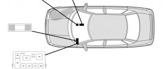
Fuse box in the passenger compartment
Despite the lack of differences between the mounting blocks of the “sevens” with carburetor and injection engines, the latter are equipped with an additional block, which is installed in the cabin under the glove compartment. The block consists of blocks with relays and fuses:
- main relay;
- fuel pump relay;
- fan relay.
Fuses are designed to protect:
- main relay;
- electric fuel pump;
- electronic engine control unit.
How to remove the power supply
To replace the switching devices and fuses of the power unit control system, it is necessary to remove the bracket on which they are mounted. To do this, perform the following steps:
- Remove the negative terminal from the battery.
- Using a size 8 wrench, unscrew the two nuts that secure the bracket to the body.
Since the additional block does not have any printed circuit board, there is nothing to restore in it, except for replacing the elements installed in it.
Having familiarized yourself with the purpose of the fuse box on the VAZ 2107 and step-by-step instructions for its dismantling and repair, finding and fixing the fault will not pose any particular problems even for novice car owners. It is important to monitor the condition of the fuses and promptly replace failed elements with parts of the same rating, which will eliminate the need for more serious repairs.
Skoda Kodiak forum
- SKODA-KODIAQ.RUFORUMOperationElectrics and light
How to remove the fuse box in the passenger compartment
How to remove the fuse box in the passenger compartment
Post by Rustik88 » Mar 07, 2022, 10:59 pm
How to remove the fuse box in the passenger compartment
Post by shav68 » Mar 08, 2022, 10:48 am
How to remove the fuse box in the passenger compartment
Post by Rustik88 » Mar 08, 2022, 07:37 pm
How to remove the fuse box in the passenger compartment
Post by Rustik88 » 09 Mar 2022, 20:38
How to remove the fuse box in the passenger compartment
Post by shav68 » Mar 10, 2022, 00:47
How to remove the fuse box in the passenger compartment
Post by Rustik88 » Mar 10, 2022, 06:47
How to remove the fuse box in the passenger compartment
Post by Liskoff » Mar 10, 2022, 11:00 am
How to remove the fuse box in the passenger compartment
Post by Serg118 » Oct 18, 2022, 11:22 pm
- about Skoda Kodiaq
- ↳ Selecting and purchasing a new Skoda Kodiaq
- ↳ Buying a used (used) Kodiak
- ↳ Test drives and reviews in the media
- ↳ Skoda Kodiaq vs Competitors
- ↳ Dealers and service
- ↳ Insurance, lending
- ↳ Insurance from Insurance Team
- Exploitation
- ↳ Operation of Skoda Kodiaq (general questions)
- ↳ Maintenance
- ↳ Selection of oil. Change of oil
- ↳ Engines
- ↳ petrol 1.4 TSI (125 hp)
- ↳ petrol 1.4 TSI (150 hp)
- ↳ petrol 2.0 TSI (180 hp)
- ↳ diesel 2.0 TDI (150 hp)
- ↳ Suspension and steering
- ↳ Brake system
- ↳Transmission
- ↳ Electrics and light
- ↳ Outdoor lighting
- ↳ Electronic driver assistance systems
- ↳ Alarm, security systems
- ↳ Wheels and tires
- ↳ Body
- ↳ LCP
- ↳ Salon
- ↳ Heating, ventilation, air conditioning
- ↳Seats
- ↳ Multimedia, navigation, car audio
- ↳ Tuning
- ↳ Engine chip tuning and DSG
- ↳ Activation of hidden functions, adaptations, OBD adapters
- ↳ Do it yourself
- ↳ Documentation
- Skoda Kodiaq Club
- ↳ Club partners
- ↳ Let's get acquainted
- ↳ Club life
- ↳ Regions and meetings
- ↳ Moscow
- ↳ St. Petersburg
- ↳ Central Federal District
- ↳ Northwestern Federal District
- ↳ Privolzhsky Federal District
- ↳ Ural Federal District
- ↳ Siberian Federal District
- ↳ Far Eastern Federal District
- ↳ Southern Federal District
- ↳ North Caucasus Federal District
- ↳ Belarus
- ↳ Ukraine
- ↳ Baltic
- ↳ Club symbols
- ↳ Help for teammates
- ↳ Owner reviews / Logbooks
- ↳ Work of the forum / website / VK group
- Miscellaneous
- ↳ Other Skoda car brands and models
- ↳ Flea market
- ↳ Cars
- ↳ Wheels and tires
- ↳ Spare parts and accessories
- ↳ Other products
- ↳ Archived announcements
- ↳ Joint procurement
- ↳ Gazebo
- ↳ Congratulations
- ↳ Sports club
- ↳ Women's club
- ↳ Recreation and hobbies
- ↳ House and cottage
- ↳ Positive
- ↳ Legal issues, communication with the traffic police
- ↳ Travel
Who's at the conference now?
Currently browsing this forum: no registered users and 0 guests
Fuse box VAZ 2107
The fuse box is an important component of every car, through which electrical circuits are protected from overcurrents and short circuits. The VAZ 2107 is also equipped with a fuse box, of two types: old and new. Let’s find out in more detail what this device is, as well as what main factors it is responsible for.
Where is the fuse box on the VAZ 2107
A fuse is a device that allows you to protect an electrical circuit from currents greater than the required value and short circuits. The fusible elements are located on a kind of board, which is located under the hood of a VAZ 2107 car. This device contains not only fusible elements, but also switching relays.
This location of the VAZ 2107 fuse box is not accidental, because it is under the hood that the terminals of the main electrical circuits of this car are located. If you open the hood, the object is located near the windshield directly opposite the passenger seat. Where is the new fuse box located? Both new and old, they are located directly under the hood. They both have differences, albeit minor ones.
To find out what the differences are between the new and old samples, consider both types.
Old style circuit
Two types of such electrical devices were installed on the VAZ 2107. Structurally, both of these products are different, but in general they perform the same function. Only the layout of the fuse links and relays differs, which we will now learn about in more detail.
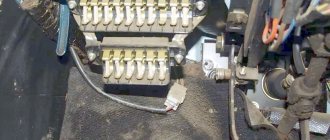
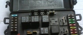
The block on the old-style VAZ 2107 was installed only on carburetor cars. Although a new model can be installed on the carburetor. The old unit is equipped with 17 fuses. Each element is responsible for protecting one or more circuits. The old-style power supply unit is shown in the photo above, where the fusible elements are visible. They are also obsolete samples, which become more difficult to find every year.
For convenience, below is a table of the purpose of each element on a VAZ 2107 car.
In addition, consider the purpose of each relay. The relay count starts on the left in the photo below. The leftmost relay is responsible for switching the rear window heating circuit. The second relay on the left is designed to control the circuit of headlight cleaners and washers. On some models this element may not be available. The third element is designed for switching audio signal circuits. The fourth socket, which is empty in the photo, is intended for switching the cooling system fan motor circuit. VAZ 2107 cars after 2000 do not need this element. The last two relays are designed to control the high and low beam headlight circuits, respectively.
This is what the old-style VAZ 2107 fuse box looks like. Now let's look at what the new element is and what differences it has.
Scheme of the new power supply
VAZ 2107 injector cars and some of the latest carburetor models are equipped with new types of fuse blocks. The photo below shows such a product for comparison.
The new “sevens” are equipped with a box similar in size, only with modified fusible elements. These are new type fusible links that are used in modern cars. First, let's look at the purpose of each fusible product.
Now let's look at the purpose of each relay. And the purpose of each product is similar to the old model. It follows from this that both devices perform identical functions, and differ only in the shape, location and types of elements.
Additional block on injection “sevens”
The injection VAZ 2107 is equipped with an additional fuse and relay device, which is located directly inside the car under the glove compartment. This device includes 3 relays and 3 fusible elements. All these devices are responsible for protecting the main relay, engine ECU and electric fuel pump. The photo below shows a view of this device.
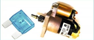
VAZ 2107 owners often wonder where the starter relay is located. This relay is not included in the unit, but is located separately. It is located in the engine compartment area on the right mudguard.
Features of product replacement
Replacing the fuse box is usually only required if there is a need to install a new one instead of the old one. The replacement principle is accompanied by the following actions:
- First you need to de-energize the car by removing the minus terminal.
- The air filter housing is removed.
- Find the wiring harness that is connected to the mounting block and disconnect it.
- The shelf under the dashboard is being dismantled.
- The glove box body is removed.
- A second harness is found that fits the power supply.
- The power supply mounting bolts, of which there are two, are unscrewed.
- The product is dismantled.
- A new device is installed in its place.
Further actions are the reverse of the initial dismantling procedure. You need to attach the box, secure it, connect the wires and install the air filter housing.
If you need to replace the fusible element, then this must be done with the battery terminal disconnected. It is necessary to replace failed elements, which can be detected visually or using a tester. Fuses should only be replaced with ones of similar current value, otherwise this may lead to unpleasant consequences.
The VAZ 2107 has another fuse that is directly responsible for the functioning of the fog lights. Many “Seven” car owners are scratching their heads in search of this ill-fated device. After all, its location is not entirely standard. This device is located directly under the console central panel. There, there is a button for turning on the fog lights, next to which the fuse is located. To replace it, you will need to remove the panel. This unit is located in a round oblong contact box. To replace it, you need to remove it and replace it with a new one.
Working with fuses does not require special knowledge and skills, since everything is done so that any motorist can figure it out on their own. This material will help you troubleshoot any electrical device.
Where are the devices located and what are they responsible for?
To begin with, we suggest finding out which fuses and relays are responsible for what, what the electrical pinout of devices on the injection and carburetor VAZ 2107 is. The main part of the parts used are installed in the main device, which is located in the engine compartment. The shield is located directly under the windshield, opposite the passenger seat.
Domestic "Sevens", be it a carburetor or an injector, can be equipped with two types of devices - old and new. Accordingly, the description and diagram of electrical equipment in them will differ slightly. Old-style devices were used on cars of early years of production, new ones were used on later versions.
If we talk directly about the injector and carburetor, the electrical circuit of the devices does not depend on the type of fuel supply system. That is, both carburetor and injection versions of cars can be equipped with new and old units. In versions of cars released later, the unit can be installed inside the car under the glove compartment.
Old type
Old style block diagram
| № | What is it used for? |
| 1 | This component is designed to protect the electrical circuit of the reversing headlights, the heater motor, the dashboard light, and the rear window heating system relay. |
| 2 | Necessary to protect the windshield wiper motor, windshield cleaning system and optics, if provided by the manufacturer. |
| 3, 4 | Auxiliary connectors can be used when adding new devices. |
| 5 | Operation of the rear window heating system. |
| 6 | Designed to ensure the operation of the cigarette lighter. Sometimes this fuse is responsible for the radio, depending on the car. |
| 7 | The device is used to ensure uninterrupted operation of the motor of the ventilation device cooling the radiator, as well as the horn. |
| 8 | Emergency light signaling. |
| 9 | Uninterrupted operation of anti-fog optics. In some "sevens" this fuse is responsible for the operation of the generator voltage regulator. |
| 10 | The element is responsible for the functioning of the instrument cluster, the low battery indicator on the combination, as well as other light bulbs. |
| 11 | Stop lights, sources of internal light of the car body. |
| 12 | High beam headlight, right, activation coil of the optics cleaning system relay. |
| 13 | High beam headlight, left, light bulb on the control panel for turning on the high beam headlights. |
| 14 | Side lighting, license plate light indicator, under-hood light. |
| 15 | Dimensions, light of the instrument panel, glove box, cigarette lighter. |
| 16, 17 | Low beam safety element. |
| 18 | The device is designed to protect the electrical circuit of low-beam headlight bulbs. |
| 19 | This element is necessary to protect the circuit of high beam optics bulbs. |
| Reserve socket | Used to connect the engine fan motor relay in vehicles manufactured before 2000. |
| 20 | Provides the functionality of a sound signal (beep). |
| 21 | Necessary to ensure the operation of optics cleaning systems if the machine is equipped with a washer. |
| 22 | Responsible for the operation of the rear window heating system. |
Fuse and relay block VAZ 2107
The wiring harnesses of the front panel, engine compartment and rear harness of the “Seven” are connected through the VAZ 2107 fuse box . In addition to connecting electrical wiring branches, it performs the important function of protecting against overload and short circuit. Let's figure out what a fuse box is, where it is located and what each of its elements is responsible for.
Fuse box location
Most of the fuses that protect the electrical wiring of the “seven” are located in a single block located under the hood of the car. In addition to fuses, the block contains a group of relays that are responsible for turning on electrical appliances, for example, heated rear windows or headlights.
The VAZ 2107 mounting block is located under the hood near the windshield, opposite the passenger seat. Depending on the year of manufacture, the “sevens” were equipped with two types of fuse blocks: “old” and “new”. The designs of both types of blocks have slight differences, so their features and electrical circuits should be considered separately.
Important: regardless of the type of fuel supply (carburetor or injector), the circuits of one (old or new) type of “seven” fuse box are the same. Both types of blocks can be installed on injection and carburetor models.
Video “How to repair a power supply yourself”
Find out how to properly repair a device and avoid mistakes in the process from the video published below (the video was filmed by the Autoelectrics HF channel).
To protect electrical wiring and electrical equipment from short circuit currents or overloads, each vehicle has a fuse and relay unit. It is mounted in an easily accessible specific location. Through electrical cable harnesses, the fuse box is connected through circuits to electrical equipment and control devices. In this article we will look at the basic schemes of injection and carburetor models.
Old model VAZ 2107 fuse diagram
The “old” fuse box has 17 fuses. Each of them protects one or more electrical circuits. Purpose of fuses:
| Fuse number (rated current)* | Purpose of VAZ 2107 fuses |
| F1 (8A/10A) | Rear lights (reversing light). Reverse safety device. Heater electric motor. Heater fuse. Warning lamp and heated rear window relay (winding). Electric motor for rear window cleaner and washer (VAZ-21047) |
| F2 (8/10A) | Electric motors for wipers, windshield washers and headlights. Relay for wipers, windshield washers and headlights (contacts). Wiper fuse VAZ 2107 |
| F3/4 (8A/10A) | Reserve |
| F5 (16A/20A) | Rear window defroster heating element and its relay (contacts) |
| F6 (8A/10A) | Cigarette lighter fuse for VAZ 2107. Socket for portable lamp |
| F7 (16A/20A) | Sound signal. Radiator cooling fan electric motor. Fan fuse for VAZ 2107. |
| F8 (8A/10A) | Direction indicators in hazard warning mode. Switch and relay interrupter for direction indicators and hazard warning lights (in hazard warning mode) |
| F9 (8A/10A) | Fog lights. Generator voltage regulator G-222 (for car parts) |
| F10 (8A/10A) | Instrument cluster. Instrument panel fuse. Indicator lamp and battery charge relay. Direction indicators and corresponding warning lamps. Indicator lamps for fuel reserve, oil pressure, parking brake and brake fluid level. Voltmeter. Instruments of the carburetor electro-pneumatic valve control system. Parking brake warning light relay |
| F11 (8A/10A) | Brake light bulbs. Lamps for interior body lighting. Brake light fuse. |
| F12 (8A/10A) | High beam (right headlight). Headlight wiper relay activation coil |
| F13 (8A/10A) | High beam (left headlight) and high beam indicator lamp |
| F14 (8A/10A) | Side light (left headlight and right rear light). Indicator lamp for turning on the side light. License plate lights. Engine compartment lamp |
| F15 (8A/10A) | Side light (right headlight and left rear light). Instrument lighting lamp. Cigarette lighter lamp. Glove compartment lamp |
| F16 (8A/10A) | Low beam (right headlight). Headlight cleaner relay switching coil |
| F17 (8A/10A) | Low beam (left headlight) |
| * In the denominator for pin type fuses | |
Video
The video from user Konstantin Kalinnikov shows the process of removing an old-style fuse box.
| Relay circuits (its winding) for turning on the rear window defogger, reverse lamps, heater fan. |
| 2 (8A) |
| Electric motors for windshield wipers, headlights, windshield washer pumps and headlights. |
| 3 |
| Reserve. |
| 4 |
| Reserve. |
| 5 (16A) |
| Rear window heating element. |
| 6 (8A) |
| Cigarette lighter fuse, portable lamp socket, clock on the instrument panel. |
| 7 (16A) |
| Engine cooling fan electric motor, sound signal. |
| 8 (8A) |
| Direction indicators in hazard warning mode. |
| 9 (8A) |
| Generator excitation circuit. |
| 10 (8A) |
| Control devices and their signal lamps, standard turn signal lamps. |
| 11 (8A) |
| Brake signal lamps, interior lighting. |
| 12 (8A) |
| High beam of the right headlight. |
| 13 (8A) |
| High beam of the left headlight, indicator lamp for turning on the high beam. |
| 14 (8A) |
| Parking lamps for the left front and rear right lights, engine compartment lighting, license plate lighting. |
| 15 (8A) |
| Side lighting for the right front and left rear lights, instrument panel lighting. |
| 16 (8A) |
| Low beam lamp on the right side of the car. |
| 17 (8A) |
| Low beam lamp on the left side of the car. |
New VAZ 2107 fuse block diagram
On newer “sevens” a block with 17 fuses and 6 relays is installed. VAZ 2107 fuses on the “new” unit protect the following electrical circuits and devices:
- Reversing lamps, heater fan, rear window defroster warning lamp and relay, rear wiper motor and rear washer pump.
- Electric motor for front wipers.
- Reserve socket.
- Reserve socket.
- Power supply for heated rear window.
- Clock, cigarette lighter, power socket “carrying”.
- Signal and radiator fan.
- Turn signal lamps in emergency mode.
- “Fog lights” and a relay that regulates the voltage of the on-board network.
- Instrument panel lamps.
- Brake light bulbs.
- Right high beam headlight.
- Left high beam headlight, high beam warning lamp.
- Side lights (rear right, front left), license plate and engine compartment lighting.
- Side lights (rear left, front right), glove compartment and cigarette lighter lamps.
- Low beam (right lamp).
- Low beam (left lamp).
The relays of the new block perform the following functions:
- Heated rear window relay.
- Headlight cleaner and washer relay.
- Signal relay.
- Cooling system electric fan relay.
- High beam relay.
- Low beam relay.
Replacing fuses
Before replacing fuses there are two things you need to do:
- turn off the ignition;
- disconnect the ground from the battery.
Otherwise, a short circuit may occur during operation.
The procedure is as follows:
- remove the fuse box cover by releasing the fasteners;
- inspect the fuses and determine those in need of replacement (this can be seen by a broken fusible thread or black traces of its combustion);
- remove the fuse using pliers or special tweezers;
- insert a new fuse rated for the same current;
- close the lid.
1. The location of the fuses is indicated on the back of the cover of the new power supply. On an old type PSU, fuses are numbered simply from left to right.
2. It is better to check the performance of fuses not visually, but using an ohmmeter or a continuity test.[/tip]
Replacing the fog light fuse
If the fog lights stop lighting, you should check the fuse installed in the passenger compartment. To replace it you need a screwdriver. The replacement procedure is as follows:
- remove two switches from the console (the place where the radio is installed) using a flat-head screwdriver;
- use a screwdriver to press out the two latches and pull out the plastic insert from the console;
- pull out the fog light fuse housing;
- open the case and replace the fuse;
- Replace the insert and switches.
Replacing the fuse box on a VAZ 2107
VAZ 2107 fuses (injector and carburetor) are installed in standard interchangeable blocks, so replacing them is not difficult. The power supply unit can only be replaced with a unit of a similar type (old or new). This is done like this:
- disconnect the ground from the battery;
- remove the air filter housing;
- unplug the wiring harness connected to the fuse box, which is located at the bottom of the power supply unit;
- dismantle the shelf located in the cabin under the “torpedo”;
- remove the glove compartment housing;
- disconnect the second wiring harness from the power supply unit;
- unscrew the power supply bolts (the right bolt is hidden, it is not immediately visible);
- remove the fuse box;
- install a new fuse box;
- tighten the fastening bolts;
- connect the harness coming from the passenger compartment;
- install the “glove compartment” housing and the shelf under the “dashboard”;
- connect the wiring harness under the hood to the power supply unit;
- install the air filter housing;
- connect ground to the battery.
Checking and replacing the VAZ 2107 relay
Like fuses, it is better to change the relay with the ground disconnected from the battery. It is worth checking the serviceability of the relay after checking the corresponding fuses.
The relays are easily removed from their seats. To start checking the functionality of the relay, you should inspect the “legs” (contacts). If they are oxidized, you need to clean them with sandpaper or a knife.
There are two ways to check whether the relay is working. The simplest is to replace it with a new one that is known to work. If after this the operation of the electrical appliance is restored, the old relay was faulty. No - we must continue to search for the cause.
You can also apply power to the relay coil and use a continuity tester or ohmmeter to check whether the necessary contacts are closed (opened). A non-working relay must be replaced. Repair of the relay is not structurally provided.
What to do if charging is lost?
If the vehicle is equipped with a G-222 generator device and the generator has lost charging, it is necessary to diagnose the connections in the fuse box. The test is performed using a tester. Below is a list of connections that are subject to diagnostics:
- Sh4-1 - Sh11-4;
- Ш1-6 - safety device number 9 - Ш11-3, most often the reason lies in the rupture of this connection;
- Ш1-4 - Ш10-1;
- Sh5-3 - Sh10-7;
- Ш1-6 - safety element number 10 - Ш4-1.