Print this article Font size 16
With the advent of more modern technologies, domestic cars began to be equipped with on-board computers. The VAZ 2110 model was no exception.
Thanks to the on-board computer on the VAZ 2110, you can check for yourself what condition the car is in, what problems have arisen and how to solve them.
Features of connecting the VAZ 2110 on-board computer
If you have already decided or, moreover, purchased an on-board computer for your ten or another modern model of a domestic VAZ car, then the time has come to install it.
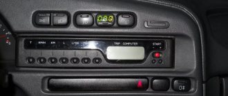
For those who are just thinking about buying a BC, we recommend that you read the previous article on choosing an on-board computer for a VAZ. Installing an on-board computer is not difficult and will take you half an hour. As a rule, the BC package already includes a contact block with the help of which connection is made to a special connector of the car. For those who don't know, the socket is located on the lower right side of the torpedo.
For additional information, a few words about the pinout of the connector for connecting the on-board computer .
As you can see, in the image shown, after connection, the on-board computer has access to all the main elements of the vehicle’s electronic on-board network. To fully launch the BC, all that remains is to connect the K-line.
What is a K-line and why is it needed?
The K-line is the channel through which the most important information is received by the bookmaker. Using this connection, data on errors that occur during engine operation, as well as its temperature, and other important diagnostic information will be available. The K-line wire is connected to the main connector, which is located under the steering column to the left of the driver's seat. Using a special wire, which also comes with the on-board computer, we make the connection as shown in the image shown.
And finally, about the diagnostic connectors of the VAZ 2110. In total, there are two types of contact blocks Euro-2 (GM) and Euro-3 (ODB-II); the photo shows the pins to which the K-line must be connected when installing the on-board computer on the VAZ 2110 .
Source
Connection diagram
The process of diagnosing an ECU using a special scanner.
Electronic control units of the VAZ-2110 are the main tool for controlling and automating most processes in the car. To adjust the software, they often resort to replacing the “brains” with more “flexible” ones and reflashing the ECU.
First of all, it is necessary to clarify several terms that will be required when considering questions about changing the electronic control unit:
- Wiring compatibility . To replace it, the connectors on the old ECU and the new one will need to match.
- Software is a predetermined algorithm that can change depending on the needs or desires of the motorist.
- The hardware component is the electronic control unit itself, boards or other components that allow the systems associated with the ECU to function normally.
For the VAZ-2110 family there were two types of connectors. So, for the “brains” January 5.1.x, Bosch M1.5.4, Bosch MP7.0, and VS 5.1 there was a 51-pin connector, but for January 7.2(+), Bosch M7.9.7(+) and M73 - 81 -pin.
That is, the interchangeability of control units is caused by the pinout of the unit.
ECU January 7.2.
Differences
Fundamental differences between 81-pin blocks and blocks of previous generations:
- Overall body dimensions and weight have been reduced.
- New, more modern connectors with improved connection reliability.
- The controllers have built-in switches, therefore, instead of ignition modules, ignition coils can be used, which increase the reliability of the ECM as a whole.
- There is no software or hardware compatibility with any of the previously released units.
Even electronic control units from the same manufacturer will differ significantly in pinout. Therefore, the interchangeability of the “brains” will depend on the number of connector pins. Also, it is worth understanding that the firmware will play a big role. When changing the ECU, the motorist will have to reflash the unit for the correct operation of all vehicle devices.
ECU January 5.1.
A very important nuance remains that the software of the control unit must be compatible and comply with the type of injection, as well as the toxic standards laid down by the manufacturer.
Assignment of contacts of ECU Bosch M1.5.4, MP7.0 and January-5.1
Pinout of 55-pin ECU.
Let's look at the pinout of control units with 55-pin “brains”:
| Bosch M1.5.4 (1411020 and 1411020-70) January 5.1.1 (71) | Bosch M1.5.4 (40/60) January-5.1 (41/61) January 5.1.2 (71) | Bosch MP7.0 | |
| 1 | Ignition 1-4 cylinders. | Ignition 1-4 cylinders. | Ignition 1-4 cylinders. |
| 2 | . | Ground ignition wire. | . |
| 3 | Fuel pump relay | Fuel pump relay | Fuel pump relay |
| 4 | Stepper motor PXX(A) | Stepper motor PXX(A) | Stepper motor PXX(A) |
| 5 | Canister purge valve. | Canister purge valve. | |
| 6 | Cooling fan relay | Cooling fan relay | Left fan relay (only on Nivas) |
| 7 | Air flow sensor input signal | Air flow sensor input signal | Air flow sensor input signal |
| 8 | . | Phase sensor input signal | Phase sensor input signal |
| 9 | Speed sensor | Speed sensor | Speed sensor |
| 10 | . | General. Oxygen sensor weight | Oxygen sensor weight |
| 11 | Knock sensor | Knock sensor | Knock sensor input 1 |
| 12 | Power supply for sensors. +5 | Power supply for sensors. +5 | Power supply for sensors. +5 |
| 13 | L-line | L-line | L-line |
| 14 | Weight of injectors | Weight of injectors | Weight of injectors. Power "ground" |
| 15 | Control of injectors 1-4 | Oxygen sensor heater | Check Engine Light |
| 16 | . | Injector 2 | Injector 3 |
| 17 | . | Recirculation valve | Injector 1 |
| 18 | Power supply +12V non-switchable | Power supply +12V non-switchable | Power supply +12V non-switchable |
| 19 | Common wire. Weight of electronics | Common wire. Weight of electronics | Common wire. Weight of electronics |
| 20 | Ignition 2-3 cylinders | Ignition 2-3 cylinders | |
| 21 | Stepper motor PXX© | Stepper motor PXX© | Ignition 2-3 cylinders |
| 22 | Check Engine Light | Check Engine Light | Stepper motor PXX(B) |
| 23 | . | Injector 1 | Air conditioner relay |
| 24 | Stepper motor weight | Weight of stepper motor output stages | Power grounding |
| 25 | Air conditioner relay | Air conditioner relay | . |
| 26 | Stepper motor PXX(B) | Stepper motor PXX(B) | Weight of sensors TPS, DTOZH, DMR |
| 27 | Ignition switch terminal 15 | Ignition switch terminal 15 | Ignition switch terminal 15 |
| 28 | . | Oxygen sensor input | Oxygen sensor input |
| 29 | Stepper motor PXX(D) | Stepper motor PXX(D) | Oxygen sensor 2 input signal |
| 30 | Weight of sensors MAF, DTOZH, DPS, DD, DPKV | Weight of sensors MAF, DTOZH, DPS, DD, DPKV | Knock sensor input 2 |
| 31 | . | Reserve output high current | Rough road sensor input signal |
| 32 | . | . | Fuel consumption signal |
| 33 | Control of injectors 2-3 | Oxygen sensor heater. | . |
| 34 | . | Injector 4 | Injector 4 |
| 35 | . | Injector 3 | Injector 2 |
| 36 | . | Exit. Intake pipe length control valve. | Main relay |
| 37 | Nutrition. +12V after the main relay | Nutrition. +12V after the main relay | Nutrition. +12V after the main relay |
| 38 | . | Low-current backup output | . |
| 39 | . | . | Stepper motor РХХ © |
| 40 | . | Reserve input discrete high | . |
| 41 | Request to turn on the air conditioner | Request to turn on the air conditioner | Oxygen sensor heater 2 |
| 42 | . | Reserve input discrete low | . |
| 43 | Signal to tachometer | Signal to tachometer | Signal to tachometer |
| 44 | CO - potentiometer | Air temperature sensor | . |
| 45 | Coolant temperature sensor | Coolant temperature sensor | Coolant temperature sensor |
| 46 | Main relay | Main relay | Cooling fan relay |
| 47 | Programming permission | Programming permission | Air conditioner request signal input |
| 48 | Crankshaft position sensor. Low level | Crankshaft position sensor. Low level | Crankshaft position sensor. Low level |
| 49 | Crankshaft position sensor.High level | Crankshaft position sensor.High level | Crankshaft position sensor.High level |
| 50 | . | Recirculation valve position sensor | Programming permission |
| 51 | . | Request to turn on the power steering | DC heater |
| 52 | . | Reserve input discrete low | . |
| 53 | Throttle position sensor | Throttle position sensor | Throttle position sensor |
| 54 | Fuel consumption signal | Fuel consumption signal | Stepper motor IAC (D) |
| 55 | K-line | K-line | K-line |
Description of contacts ECU M7.9.7 / January 7.2
Let's look at the pinout of control units with 81-pin “brains”:
| № | Compound |
| 1 | 21114 - Not used / 21124 - Ignition coil 2 cylinders. |
| 2 | 21114 - Ignition 2-3. Control of the primary winding of the ignition coil, act. level is low. / 21124 — Ignition coil 3 cylinders. |
| 3 | Ignition circuit weight |
| 4 | 21114 - Not used / 21124 - Ignition coil 4 cylinders. |
| 5 | 21114 - Ignition 1-4. Control of the primary winding of the ignition coil, act. level is low. / 21124 - Ignition coil of cylinder 1. |
| 6 | Injector 2. Active level low |
| 7 | Injector 3. Active level low |
| 8 | Output to tachometer. |
| 9 | Not used |
| 10 | Fuel consumption signal |
| 11 | Not used |
| 12 | Battery, terminal 30 of the ignition switch. |
| 13 | Nutrition. Ignition switch terminal 15 |
| 14 | Main relay |
| 15 | Contact "A" DPKV |
| 16 | TPDZ |
| 17 | TPS mass / TPS mass, DND |
| 18 | Input - oxygen sensor |
| 19 | Input - knock sensor |
| 20 | Knock sensor weight |
| 21 | Not used |
| 22 | Not used |
| 23 | Not used |
| 24 | Not used |
| 25 | Bosch Only - High Current Output, Reserved |
| 26 | Bosch Only - High Current Output, Reserved |
| 27 | Injector 1. Active level low |
| 28 | Not used / DK2 heater control output |
| 29 | Not used / Engine cooling fan control output 2 |
| 30 | Not used |
| 31 | CE lamp, act. level low |
| 32 | Power supply TPDZ / Power supply TPDZ, DND |
| 33 | Power supply for mass air flow sensor |
| 34 | DPKV input, contact “B” |
| 35 | Weight of DTOZH / Weight of DTOZH, mass air flow sensor, 1 DC (UDK), 2 DC (DDK) |
| 36 | Mass of the mass air flow sensor |
| 37 | Signal input from mass air flow sensor |
| 38 | Not used |
| 39 | Signal input from DTOZH |
| 40 | Signal input from intake air temperature sensor |
| 41 | Not used |
| 42 | Not used / DND signal input |
| 43 | Not used |
| 44 | On-board voltage input at the main relay output |
| 45 | Phase sensor power output |
| 46 | Canister purge valve control output |
| 47 | Injector 4. Active level low |
| 48 | Oxygen sensor heater control output |
| 49 | Not used |
| 50 | Additional starter relay control output |
| 51 | Controller weight |
| 52 | Not used |
| 53 | Controller weight |
| 54 | Not used |
| 55 | Not used / Signal input DK2 (DDK) |
| 56 | Not used |
| 57 | Input for encoding calibration data options. The controller memory can contain 2 sets of calibration data; switching is performed by shorting to ground. |
| 58 | Not used |
| 59 | Speed sensor |
| 60 | Not used |
| 61 | Weight of output stages |
| 62 | Not used |
| 63 | On-board voltage input at the main relay output |
| 64 | Output “D” IAC |
| 65 | Output “C” IAC |
| 66 | Output “B” IAC |
| 67 | Output “A” IAC |
| 68 | Engine cooling fan relay control output, act. level - low |
| 69 | Air conditioner relay control output, act. level - low |
| 70 | Fuel pump relay control output, act. level - low |
| 71 | K-Line |
| 72 | Not used |
| 73 | Not used |
| 74 | Not used |
| 75 | Input request to turn on the air conditioner, act. level - high |
| 76 | Power steering request input, act. level - high |
| 77 | Not used |
| 78 | Not used |
| 79 | Phase sensor signal input |
| 80 | Weight of output stages |
| 81 | Not used |
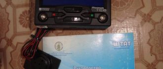
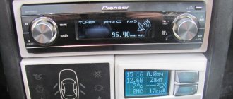
Installing the Multitronics X10 trip computer
When purchasing this item on Avito, of course, there will be nothing else in the kit except the BC. Actually, the ambient temperature sensor and the wire to the diagnostic block had to be farmed myself). There were no problems with this)
1. Take out the standard clock and disconnect it from the connector. We release the connector and it flies far and for a long time into this abyss of wires)). Next, roll up your sleeves, lower your hand into the resulting hole and feel for the standard BC block.
3. Now it is necessary to make a temperature sensor, because a used MK will not have one, the percentage is 100%) The sensor itself was the LM335Z chip.
Microcircuit in TO-92 package. It has 3 pins, the leftmost pin, if you look from the side of the marking where the edge is cut off, we don’t need it, personally I just broke it off) Barbarian, yes))
Next, take a 2-core wire and a soldering iron and begin the soldering process. I was a little lucky, and in my case, the BC included a 2-wire wire with a connector for the computer.
Solder the black wire to the rightmost leg of the sensor, the wire with a strip (red or white, depending on what you have) to the middle leg. Then we take a beautiful green heat shrink and isolate the sensor from the aggressive environment.
Then, after everything done above, we connect the sensor with a wire under the beard, then I thought about where to pull it. Selected the engine compartment. The exit to the engine compartment was made through the clutch cable seal. Next, I brought the sensor along the ties to the tow hook and fixed it there with a very beautiful yellow tie)
4. Take the trip computer, insert the pads into it and begin to figure it out according to the previously downloaded instructions from the official website)
Personally, I found the management of the bookmaker to be a little difficult, although I have now completely understood its functionality and am happy with everything).
The BC itself will determine your ECU. Plus, you will also need to make adjustments to the temperature sensor in order to achieve accurate temperature readings overboard. You can then begin on-screen programming and setting maintenance counters.
In general, I am very pleased with the work of BC. I saw what I wanted to see. I was a little upset, but more about that in the next blog.
Good luck to everyone) If you have any questions about the On-Board Computer, I will be happy to answer them.
Connecting Orion bk 16
I got some brotherly encouragement
, I’m not happy anymore, I’ve been scratching my head on how to connect it.
What is this anyway? Can anyone tell by appearance? Or how can I understand whether it is BC 16, BC 17 or BC 46
his mother?! His name is 2115-3857010 Or just connect it to the power supply and at the beginning of its switching on it should tell you who he is?
In general, on the Internet you will find a lot of comprehensive information on connection - I agree! But there is one thing! Now I will try to describe this to you But. The photo of the connection was taken from the Internet.
And if you connect a K line to it, then what? Will it be connected to ground or something?
Who can tell me what kind of stray thing I have? Maybe this is for a carb engine, I have an injector.
From the photo you will hopefully see what I want to say. There are no more wires, except for those that come out of the BC itself and I have a 9-pin block there. I don’t really know what to do, help people out.
Not long ago on Sunday, a few thoughts appeared: 1.
It’s a pity to give away money for identifying the reasons for the Check Engine light (suddenly you’ll have to buy something else with it) 2. Somewhere in Styopka’s friend there’s a bookmaker in his four that “blocks the hole in the wall”—it’s not working. 3. It’s not for nothing that I received a radio tower)
I call Styopka, explain the situation, like, let me try to revive him, give him a ride, test him, then we’ll give you a B, etc. Since my friend is a little far from electrical (though I’m not a genius myself, but I’m trying to figure it out), and there is a desire to fix the thing, the go-ahead was received almost immediately.
So, a visual inspection showed that this is an Orion BC, model #16. He came to me in the following form.
I started looking for information on it on the Internet and sorted it out along the way. As it turned out, there are new and old BK-16 models. The difference is in the firmware, in the types of screens, and in the presence of a mini-USB port inside the case.
Also, there must be a special adapter from the block located on the BC (13pin) to the block, which is hidden under the panel (9pin). The difference is in the photo.
Connecting the VAZ 2110 on-board computer. How to install the on-board computer
If you have already decided or, moreover, purchased an on-board computer for your ten or another modern model of a domestic VAZ car, then the time has come to install it. For those who are just thinking about buying a BC, we recommend that you read the previous article on choosing an on-board computer for a VAZ.
Installing an on-board computer is not difficult and will take you half an hour. As a rule, the BC package already includes a contact block with the help of which connection is made to a special connector of the car. For those who don't know, the socket is located on the lower right side of the torpedo.
For additional information, a few words about the pinout of the connector for connecting the on-board computer .
As you can see, in the image shown, after connection, the on-board computer has access to all the main elements of the vehicle’s electronic on-board network. To fully launch the BC, all that remains is to connect the K-line.
What is a K-line and why is it needed?
The K-line is the channel through which the most important information is received by the bookmaker. Using this connection, data on errors that occur during engine operation, as well as its temperature, and other important diagnostic information will be available. The K-line wire is connected to the main connector, which is located under the steering column to the left of the driver's seat. Using a special wire, which also comes with the on-board computer, we make the connection as shown in the image shown.
And finally, about the diagnostic connectors of the VAZ 2110. In total, there are two types of contact blocks Euro-2 (GM) and Euro-3 (ODB-II); the photo shows the pins to which the K-line must be connected when installing the on-board computer on the VAZ 2110 .
Troubleshooting BC
Malfunctions occur with BCs of various modifications. It would be useful for the owner to know what to do in such cases. Many failures occur when the on-board computer was not installed properly. First, you need to check the reliability of the connections. Secondly, there is a high probability of accidental damage or pinching of the K-line. Multitronics itself will report this, displaying obviously incorrect data.
You can deal with the problem yourself. If it is connected to a damaged K-line, then you need to purchase a new wire for the VAZ-2111 at a car store or on the market.
It is inexpensive, and the entire replacement procedure will take no more than 60 minutes. More time will be required if the problems of the on-board computer 2110 are caused by broken contacts. It is necessary to disconnect the device after performing a visual inspection. If bent plugs are still present, you should select new ones from the store and resolder them.
Using the BC on a VAZ passenger car allows the owner to always be aware of the technical condition of the car. The device is selected based on needs. Its effectiveness depends on correct installation.
Many owners of domestically produced cars, including the VAZ-2110, are trying in every possible way to improve their cars. And if cutting off an extra coil from the rear springs or screwing a “bench” onto the trunk lid is nothing more than “collective farm tuning,” then installing an on-board computer is a completely justified step. An on-board computer is a useful tool with which you can track engine operating parameters, current and average fuel consumption, speed and other equally important information.
How to calibrate the FLS on a standard BC
An important parameter is the fuel level in the tank. For the sensor to work correctly, it must be calibrated. For this:
So that after installing the VAZ-2110 on-board computer, it notifies you that the maximum permissible speed is exceeded, you also need to carry out “training”. To do this, switch to the average speed input mode and hold the button (top right) for several seconds. To enter an integer number corresponding to the speed, you need to use the “” “–” buttons on the front panel of the device.
READ Where are the downloaded files in Samsung?
Final installation
Make sure all electrical connections are made securely. It is advisable to solder the wires and then insulate them. Pull the harness through the interior of the console to the installation site of the BC. After this, you can connect to the wiring from the fuel level sensor in the tank.
After dismantling the dashboard, you will have access to the electrical connection terminals. You need to remove the pink wire from the gray block; it is located in the harness. Connect it to the on-board computer. To check the device, you need to connect the negative terminal and turn on the ignition.
Lada 2110 OneTen › Logbook › Block for connecting the trip computer (BC).
Block for connecting the trip computer (BC, in my case the device is Multitronics SE-50).
VAZ cars of the tenth family have a standard connector for connecting the on-board computer to the car. That is, to install the BC, everything is already provided by the factory, this is the first thing that is needed. The second is connecting the control line from the electronic control unit to the trip computer. Connection is carried out according to the following instructions:
Connecting the K-line and assigning contacts to the BC block
Types of diagnostic pads
Some of the wires of the trip computer connector had to be restored because they were torn out; it was not originally installed in the car.
The automatic switching on of the interior lights was implemented through the on-board display unit, but it is now missing. Therefore, to preserve this function, it is necessary to connect the following contacts according to the diagram:
Likes 64 Shares: Subscribe to car
Stories from our readers
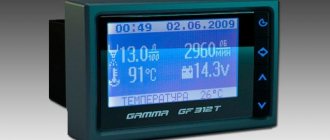
Digital errors on the on-board computer are easy to decipher. To fully launch the BC, all that remains is to connect the K-line.
By the way, a similar model has now gone on sale, but with a color display.
The best solution would be to install it in the central part of the console, if space allows. In installing an on-board computer, in principle, there is no hassle with wires and nuts unless, of course, no one tried or changed anything in the car before you. After removing it, you need to find a bunch of wires with a 9-pin connector; it is available on all VAZ model cars. The readings should reset to zero.
Check the wire according to the diagram described above. Let's start removing the on-board computer: First, you need to remove the radio, but first disconnect the negative terminal from the battery. The wire with the sensor can be taken out from the passenger compartment through a hole in the engine shield under the speedometer cable, next to it. The preliminary stage of installing an on-board computer on a car is to select the appropriate tools that will be needed during the installation process: a classic set of automotive screwdrivers; directly the on-board computer of the car; standard wire is about 1 meter. BK10 on VAZ2110
instruction manual on how to connect and configure the BC
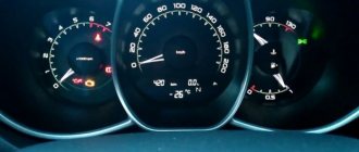
The VAZ-2110 on-board computer is used to control vehicle systems. In its original configuration, the car leaves the factory without a smart gadget, but this does not prevent the driver from purchasing it. Before this, it is necessary to evaluate the technical characteristics of the models on the market. Each of them is designed for specific operating conditions of the VAZ-2111, 10 or 12.
Functional purpose of the device
The development of the technical component of vehicles has led to an abundance of electronic and mechanical devices that control the operation of the car. Each of them reflects one or another indicator, which a person does not always have time to analyze. This is where the VAZ on-board computer will help, taking control of what is happening. In addition to monitoring the operation of vehicle systems, it will promptly inform the owner about a failure.
Another advantage is that the standard on-board computer analyzes the technical condition of the car within the specified parameters. In practice, this means that the driver can ask a question regarding the presence of components or assemblies whose performance exceeds the technical norm. Preventative analysis reduces the likelihood of downtime due to technical failure. The VAZ trip computer differs in the available options depending on the configuration:
Installation recommendations
The efficiency of the device is determined at the stage of selection and subsequent installation. An on-board computer (BC) is selected for the VAZ-2112, which collects and analyzes incoming information. Regardless of the model, it is equipped with a Check Engine light. When it is triggered, the bookmaker will independently determine that it is not working.
Setting an alarm
- Press button 4 in Alarm mode.
- Use buttons 5, 6 to set the desired hour value.
- Press button 4. Use buttons 5, 6 to set the desired minute value.
- Press button 4 to complete the alarm setting.
- In the “Current time” mode, the alarm symbol will light up (the alarm is on).
* If the counter of any of the accumulated parameters (“Travel time”, “Travel time with stops”, “Total consumption”, “Trip mileage”) overflows, all accumulated ones, as well as calculated ones (“Average fuel consumption”, “Forecast”) are reset mileage on remaining fuel", "Average speed") parameters, with the appearance of a two-tone sound signal.
Turning off the alarm
- Press button 4 in Alarm mode.
- Press button 1 to turn off the alarm. “—.—” will appear in the digital digits, and in the “Current time” mode the alarm symbol will not light up (the alarm is turned off).
Adjusting the brightness of the indicator backlight
When the side lights are on, the illumination level is adjusted using the instrument scale illumination regulator. When the side lights are turned off, the backlight level is adjusted by software:
- — press button 4 in the “Traveling time with stops” mode. All single segments (pictograms) will be displayed on the indicator, which is a sign of the backlight level adjustment mode, and the digital digits will display a number corresponding to the backlight level as a percentage of the maximum value;
- — use buttons 5, 6 to set the required level of backlight brightness; press button 4 to end the brightness adjustment mode.
Source
We connect the on-board computer to the VAZ-2110 with our own hands
Many car enthusiasts have encountered the problem of connecting an on-board computer. The change procedure may require some knowledge and skills, but it is realistic to do the operation yourself, with your own hands.
Video about connecting the on-board computer to the VAZ-2110
The video will tell you about choosing and connecting the on-board computer. And also, he will tell you about all the subtleties and nuances of the procedure.
Features of the Clock
The mode includes a clock, date, alarm clock with 7 polyphonic melodies, control of external contacts of the Omega 115 system. In addition, if you wish, you can go through key control points in demo mode. In this menu you can adjust the screen brightness and see the temperature sensor data.
By installing an electronic device, you won’t worry about how much gasoline is left in the tank and whether you can get to the desired location without refueling. Taking into account your driving style, the BC will predict how many kilometers you can drive on the remaining amount of fuel.
Attention! The maximum adaptation of the on-board device of the Omega 115 system to the VAZ 2109i-15 makes it possible when monitoring the gasoline level not to calibrate the tank; it is enough to select the appropriate type of panel. The system includes the ability to determine the ambient temperature using a temperature sensor manufactured by Philips
For the convenience of working with the on-board computer, in the “Information about bookmaker” section there is a section in which, in the demonstration mode, you can get information about all the available functions of the computer (Demo mode). In this mode, the Omega 115 on-board computer supplements the operating instructions. By launching the “Multi-display” section, you can simultaneously monitor the readings of several of the parameters you most need (three modes of this function are available)
The system includes the ability to determine the ambient temperature using a temperature sensor manufactured by Philips. For the convenience of working with the on-board computer, in the “Information about bookmaker” section there is a section in which, in the demonstration mode, you can get information about all the available functions of the computer (Demo mode). In this mode, the Omega 115 on-board computer supplements the operating instructions. By launching the “Multi-Display” section, you can simultaneously monitor the readings of several of the parameters you most need (three modes of this function are available).
Choice of "Brains"
AvtoVAZ Lada 2110 cars have been equipped with several electronic control units throughout their production history. Thus, the following ECUs can be found on vehicles:
According to the experience of motorists and the recommendations of specialists, it is best to take electronic control units marked Bosch MP7.0, January 7.2+ and January 5.1.
If you have to change the remaining blocks, it is recommended to take an ECU with these markings, since they are more “flexible” for changing the software.
On-board computer diagnostics
Faulty sensors can be determined using ECU diagnostics.
To identify faults in the electronic control units of the VAZ-2110, diagnostic equipment is used. Usually they use a tablet or laptop with special software. Also, the motorist, if the operation is performed independently, will need a special OBD II cable.
The process of diagnosing an ECU using a laptop.
Diagnostics are carried out to determine errors in the electronic control unit and troubleshoot problems in on-board systems, especially on engines. After identifying the error, it is necessary to decipher and find the cause of the malfunction in order to eliminate it.
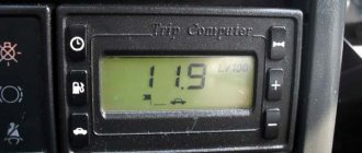
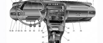
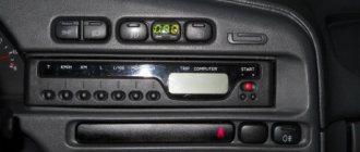
Description of the standard on-board computer BAZ 2110
- how much time has passed since the start of the trip
- what is the fuel consumption
- At what average speed are you moving?
- Approximately how long can you drive on the remaining fuel?
- outside air temperature (we said above that for this you need to install a corresponding sensor)
Bottom right
How to disable the speed signal on a regular computer? I bought a car 2110, it has a standard on-board warning system, I was able to signal more than 60 km/h. Please tell me how to turn this off?
It seems that in the current speed indicators you need to press the right middle button and change the indicators.
Tell me, brothers, my main computer has burned down, and now it won’t start, it’s already been six months. It’s worth it, what do you advise?
I have something with time on my bank account, it used to always work, now it doesn’t, I haven’t touched it or changed it. It's worth the staff. What should I do? I tried to set a new time, but they still didn’t work.
Tell me, I have COMFORT X11, it notifies me (including by voice) when the voltage of the on-board network is below 11 Volt, how to turn it off or lower the level at which it is issued forbearance? Thank you!
If the time stops, you need to replace the lithium battery, it is the same as in any home computer
Worried about the instrument panel? Is any pointer not working? Do you want to change the backlight? Then read this article. And you will learn how to remove it correctly, what malfunctions occur most often, and how to fix them.
What breakdowns often occur with the Gazelle steering gearbox, how to fix them and how to remove the gearbox if there is no hole or viewing platform. Everything is written simply and clearly.
On-board computer options
On-board computer STATE X1M-station wagon.
Description STATE 115 X-23 M - (discontinued)
On-board computer with text display (16 characters on 2 lines) and blue backlight.
Sound accompaniment with a squeaker.
This BC does not have an input for connecting gas equipment.
Compatible with all types of BOSCH, JANUARY, ITELMA controllers, including E-GAS.
Video review of BC State 115 X-23 M
Trip computer with two independent mileage and consumption counters, as well as the ability to view previous parameter values (before reset) for one type of report.
Diagnostic tester, allows you to read errors and operating parameters of the ECM.
Eight multi-displays (MD) with a variable set of parameters and one multi-display with automatic change of parameters depending on current conditions.
The BC has a “TAXI” mode, which allows you to display the cost characteristics of the trip and the cost of fuel consumed.
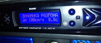
The BC has a “DYNAMICS” mode, which allows you to measure and display the dynamic characteristics of the car.
Functions PLAZMER (drying and warming up spark plugs for cold engine starts), TROPIC (automatic control of the cooling system fan when the engine temperature specified by the user is reached), FORCING (reset of the controller learning memory when switching “gasoline” / “gas”, leading to the state of the original factory settings) installations for gasoline with an octane number of at least 95)
Emergency alarm for critical events, as well as warnings about the expiration of insurance and the need for maintenance.
Photo of the on-board computer STATE 115 X-23 M:
Instructions and manuals STATE 115 X-23 M:
Installation and Operation Guide - Download PDF
Firmware and programs for the on-board computer STATE 115 X-23 M - SOFTWARE STATE 115 X-23 M
Possible names:
staff, shtat, staff 115×23, staff x23, 115 x23-m, x23m, on-board computer, trip computer
| Main characteristics of the on-board computer | |
| Fastening | To a regular place |
| Display type | LCD RGB |
Avtobortovik.ru team will ensure delivery of goods to any city in Russia, as well as to all CIS countries and the world. We work with the country's leading forwarding services - Russian Post , Business Lines.
Cost and delivery time:
Type of departure
Delivery period
Cost of delivery
Russian Post Ground (prepaid)
200-400 rub. (depending on the region and weight of the item). When ordering from 3000 rub. Free shipping applies.
Russian Post Ground (cash on delivery)
from 300 rub. (depending on the region and weight of the item). Shipping costs are pre-paid (new customers only).
Russian Post 1st class Air (prepaid)
from 300 rub. (depending on the region and weight of the item).
Russian Post 1st class Air (cash on delivery)
from 400 rub. (depending on the region and weight of the item). Shipping costs are pre-paid (new customers only).
Business lines to the terminal (prepaid)
from 350 rub. (depending on the region and weight of the item). Delivery costs are paid upon receipt.
International delivery (prepaid)
600-1500 rub. (depending on the country and weight of the item).
After shipping the goods, we send you a message with the bill of lading number, by which you can track the movement of your parcel. To track the movement of your parcel using the bill of lading number, follow the link:
To a simple question - do you need a car computer in your car - many of us will answer in the affirmative, although we may not fully understand all the tasks and problems solved by the State family of on-board computers. It's not even a matter of wanting to have a nicer and more convenient information system. Tolyatti specialists, who have developed several interesting models, tried to guess the demand for more comfortable conditions for driving a car. Support for the State car on-board computer is carried out by specialists from State LLC together with Tolyatti State University.
The goals for which a car enthusiast puts a new electronic device in his car, often with his own hands, are easy to list: