Diagnostics, testing and repair of the VAZ 2104 generator. I also eliminate additional problems with charging.
Today we are working on a VAZ 2104 with an injection engine. Problem: no battery charge. This is indicated by the corresponding light on the instrument panel + I checked with a multimeter.
In this post I’ll tell you and show you: how to remove the generator from a VAZ 2104; how to determine its malfunction - why the battery is not charging; How to repair a generator yourself.
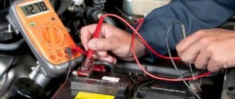
I connect the multimeter to the battery and see that it is slightly discharged. Now the voltage on it is 12.5 V. I try to start the car - there is no charging, the light on the panel is on. I try to start it a second time and it doesn’t work. The starter solenoid relay operates, but the car does not start. The battery voltage is about 12 V.
I'm trying to start the car using a 16 A/h jump starter, which I bought on Aliexpress - goo.gl/63Js4B. The car started up and the battery was charging.
Dismantling the generator. We de-energize the car and remove the voltage from the generator by removing any of the terminals from the battery. To do this, I use a 10mm wrench. I decided to remove the battery because I need to get to the tension bolt.
Using a device that I made with my own hands, based on a computer power supply, I charge the removed battery. While I'm doing the repairs, the battery will charge a little.
How to remove the generator on a VAZ 2104? First, let's free it from the belt. To do this, unscrew the nut and bolt and remove the belt. You need to remove the positive power terminal from the generator itself. One wire of the generator is simply pulled out, the other is held in place with a 10mm nut. And finally, unscrew the lower mount of the generator. We do this from under the car.
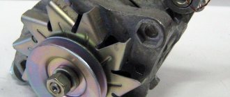
Disassembling the generator. We immediately see that the generator cover has melted. Several diodes also burned out. Most likely there was a short circuit.
The diode bridge needs to be replaced. To replace the diode bridge you need to unscrew several bolts; remove the regulator relay (modification 9402.3702) and capacitor; Remove the starter winding contacts. I remove the relay and look at its integrity and performance. The brushes are already worn out, so if the relay is working, I will re-solder them.
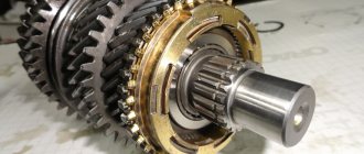
The slip rings on the armature are intact. At the same time, I check the bearings; in my case, the outer one is in fairly good condition.
The big advantage of this generator is that it can be repaired without resorting to soldering. All parts are replaceable.
I call the stator winding. There are 3 phases, there should be the same resistance between them. I will also spin up the generator and look at the windings to make a visual assessment. To do this, unscrew the 4 bolts using a 8mm socket. Remove the back cover of the generator. The winding was not burned.
The contact rings to which the brushes are attached have no holes, but there is already a hook. The rear bearing is noisy, it is dry, it is advisable to change it.
I check with a multimeter that the winding is not pierced to the housing.
How to check the generator regulator relay? I connect a light bulb to the brush load. I supply minus and plus power to the relay. For this I use a power supply. Additionally, I connect a voltmeter to see what voltage I am applying to the voltage regulator. When high voltage is applied, with the relay working, the light should go out. At 14.5 volts, the light goes out, which means everything is working.
As a result, I need to change the diode bridge, the brushes on the relay regulator, replace the insulators on the stator winding and the rear bearing.
How to remove the rear generator bearing? To begin with, I wanted to use a puller, but it could damage the armature axis, so I used 2 wrenches. This way you can do without a special tool.
I am installing new spare parts on the generator. Since the store didn't have a new regulator relay, I will replace the brushes with a relay that has them in better condition.
To insulate the conductors that come out of the stator winding, I used heat shrink tubing.
Generator assembly. Before assembly, I clean the parts from oxides using sandpaper, a knife, and a screwdriver. I lubricate the seating surfaces of the lid with lithol. Make sure that there are dielectric washers made of textolite on the bolts under the terminals, and that the terminal does not touch the bolt. Otherwise there will be a short circuit. I ran the whole thing with a multimeter. I install the generator in the car, tighten the belt, and return the battery. I start the car and check if there is a charger. Another problem has emerged: voltage is lost on the ground wire that goes to the engine. Most likely the winding in it has rusted. I implemented a loop, using braided wire, from the intake manifold mount to the mass bolt. With this jumper I eliminated the losses.
How to test a generator with a multimeter
The diode bridge of the generator can be checked with a multimeter, but you can also use the stand that was used to check the regulator.
But before that, first of all, without removing the rectifier bridge from the generator, connect the red wire of the tester to terminal 30 of the generator, and the black wire to the housing. Set the tester operating mode to dial (diode icon). If it is not there, then set it to 1-2 kOhm. The multimeter should show infinity. If the readings are different, the diode bridge is faulty.
Then check the current rectifiers for breakdown. Leave the positive (red) probe on terminal 30, touch the negative one to the bridge mounting bolts one by one. The multimeter display should show infinity in all cases; any others mean a breakdown.
Next, connect the positive probe to the axle mounting bolts, and the negative probe to the generator housing. In this case, the tester should also output infinity.
But in practice, such verification is most often not enough. In most cases, it is necessary to ring the generator in more detail.
Careful testing
To do this, unscrew the fastening bolts of the rectifier unit, disconnect the copper wires of the stator winding and remove the diode bridge from the generator. Now you can test each semiconductor individually. Before checking, it is advisable to rinse the stabilizer with running water using a medium-hard brush, and then dry thoroughly. For quick drying, a hair dryer is quite suitable. Attach one of the tester probes to the diode plate, connect the second to the central terminal of each diode fixed to this plate. Then swap the probes. In one case, the multimeter should show infinity, in the other - a nominal resistance of approximately 570-590 Ohms. Rectifiers are considered faulty if:
- In the first and second measurements (when the polarity was changed), the multimeter readings are the same;
- Diode resistance is greater or less than nominal values.
Perform the same actions with the second plate of the diode bridge. If a fault is detected in one or more diodes, it will be easier to replace the entire rectifier unit. True, there are craftsmen who replace failed diodes individually, but such work requires a certain skill and dexterity.
Checking the armature and stator windings
Further inspection requires completely disassembling the generator. First of all, visually check the anchor. Brush rings should not show any blackening, chipping or wear on the treadmills. Blackening and slight wear can be smoothed out with zero-grade emery cloth. Rings with deep grooves must be replaced or, if the thickness of the rings allows, turned on a lathe. The armature winding should not have a distinct smell of burning. The color of the winding must be uniform and free of damage and breaks. To check the armature winding for a break, you will need a multimeter. Set the operating mode to continuity testing or resistance measurement and connect the probes to the brush rings. The winding resistance should be within 3-5 Ohms. Then leave one probe on the ring, connect the other to the body. The multimeter display should show infinity.
The generator stator is diagnosed after removal from the housing. First of all, carry out a visual inspection. There should be no visible damage to the wire or its insulation. Then connect the tester wire to the stator housing. With the second wire, touch the terminals one by one. There are only three of them. The tester must be in dialing mode. If the display shows infinity, this indicates that the stator is working properly.
Further testing consists of diagnosing the windings. The resistance of all three windings must be the same.
Before assembling the generator, you need to check and, if necessary, replace the bearings. When turning, they should not jam or make a creaking sound. This means that they are very worn out and will soon fail. Therefore, it is better to replace them immediately.
Common breakdowns
Generator faults can be electrical or mechanical. These include:
- loss of functionality of the voltage regulator;
- breakdown of the rectifier unit (diode bridge);
- short circuit of stator windings;
- current short circuit in the rotor winding;
- wear of bearings and brushes.
Read also: Safety precautions when working with a soldering iron
Voltage regulator
The purpose of this unit is to normalize the voltage before feeding it into the automotive electrical circuit. You can check the serviceability of the regulator by checking the voltage that it supplies to the battery terminals. This indicator depends on the model and brand of the vehicle and varies between 13.5-15.5 V. Therefore, you should find out in advance what voltage your particular type of regulator produces. This can be done by studying the manual for using the machine. For example, you can take a VAZ 2107 or 2110 car, since these vehicles have the most typical faults associated with the integral and relays.
Using a Multimeter
To check the VAZ 2110 generator with a multimeter, you need to switch the device to voltmeter mode. Then you need to connect its probes to the battery terminals. The most important thing is to observe the polarity and turn off the car engine. The voltage normally varies from 12 to 12.8 V. Next, the procedure should be repeated, but with the engine running. The voltage readings should rise to 13.5-15.5 V. Lower and higher voltage values indicate a malfunction of the generator.
Checking the generator without removing it from the car
A bridge of diodes performs the functions of a kind of alternating current converter. It contains three negative and three positive diodes.
Before checking the bridge, you need to disconnect all the wires coming from it and from the voltage regulator. You also need to remove the ground anchor from the battery in advance. First you need to check the rectifier for short circuits. We activate the ohmmeter mode on the multimeter and connect the red (positive) probe to the positive contact of the diode bridge, and the negative probe to the surface of the housing of the generator itself. If the rectifier is fully operational, then the readings of the measuring device will go to infinity. In other cases, the rectifier will be inoperative.
Testing of stator and rotor windings
A common breakdown of a car generator is a short circuit in the windings. It occurs when current surges are too intense, brushes wear out and liquid gets in.
So, you need to remove the rotor and find a pair of slip rings on its structure that will need to be ringed. Having started the ohmmeter mode on the multimeter, we connect the probes to these rings. Normal resistance is 2-6 ohms. If you get large values, then there is a loss of contact between the slip rings. If the device shows lower values, then an interturn short circuit has occurred.
The starter has several windings at once. They need to be checked separately. However, first you need to disconnect the wires that connect the diode bridge and the winding terminals.
Then you should measure the resistance between zero and the terminals of the windings. The normal value is no less than 0.3 Ohm.
Wear of brushes and bearings
If you have already disassembled the generator, then it is advisable to check the condition of the brushes. They can wear out or break due to misalignment of the rotor shaft. If the brushes are damaged, they should be replaced with new ones.
Inside a car alternator there are a pair of bearings. One is fixed on the rotor shaft, the other is in the center of the cover. The whistling and hum of the generator when the engine is running is a clear sign of bearing wear. In this case, the generator housing can become very hot. If you notice such signs, it is better to replace the bearings immediately, otherwise you may encounter more serious problems.
You can check the bearing by removing the belt from the generator and trying to rotate its shaft with your own hand. If the part rotates freely and easily, then everything is in order. If it is difficult to rotate the rotor, then you should not delay replacing the bearings.
How to check the generator for performance? Self-check and repair of the generator
A generator is a typical electrical station that provides energy to all engine systems: power, cooling, ignition, so its failure will inevitably lead to other malfunctions. To prevent breakdowns, you need to systematically diagnose it, and if problems cannot be avoided, repair it immediately.
In this article we will talk about how to check the generator for performance without resorting to the help of professionals. But before that, let's look at the symptoms of its possible defects.
Checking the generator and its components using a multimeter
A car alternator is a fairly reliable device and can last for many years without replacement. It most often breaks down due to water getting into it, which leads to rusting and destruction of its parts. Its bearings may also wear out.
Where to start checking the generator?
To begin with, it is advisable to remove it from the machine by disconnecting the mounting bolts and removing the belt from the pulley. Next, let's examine it carefully.
Pay attention to the color of its stator winding (the stator is the outer part of the generator, which is wound with a thin copper wire). This winding should not have any traces of darkening, black spots or obvious signs of burning.
The fact is that the copper wire with which the stator is wound has varnish insulation, which begins to darken when overheated excessively, so if the generator was operating with an overload, the wire becomes dark and this is immediately noticeable
It is important to distinguish between the color of the winding that has darkened due to high temperature and that is simply dirty due to oil or dust.
Generator circuit for injection engines
In fact, the design of the generator set is not much different from those installed on carburetor engines. Only the type of excitation and serviceability monitoring differ. The dashboard contains not only a warning lamp, but also a voltmeter; these two devices allow you to assess both the presence and level of charging. Current flows through the lamp filament and is supplied to the field winding when the engine starts. The connection diagram for the VAZ-2107 generator, regardless of the year of manufacture, implies operation in the following mode:
- When the ignition is turned on, power is supplied to the excitation winding. A magnetic field appears around the armature.
- When the crankshaft rotates with the starter, the generator armature also begins to move. With the help of movement and a magnetic field, a potential difference arises at the ends of the stator windings.
- From the windings, voltage (alternating, three-phase) is supplied to the rectifier unit, and from it to terminal “30” of the generator.
- Pin “30” is connected to the battery (positive terminal). Consequently, the entire electrical system is powered and the battery is charged.
In this case, the battery and generator G221A work in parallel. The connection diagram for the VAZ-2107 with carburetor and injection engines is almost identical, with only minor features.
Lamp test
A lamp test is testing a generator using a “fog light”. The diagnostic task is to determine whether the generator rotates correctly when exposed to drill speeds. In this case, the light bulb plays the role of an indicator - if the generator rotates normally, then it (the light bulb) should light up.
It is important to know that a working generator should produce a voltage within 14.1-14.5 V. And at the same time, the voltage should not jump or have differences. In other words, the voltage must be stable.
To carry out this type of testing, the autogenerator will have to be removed from the car and the following steps must be taken:
- clamp it in a vice so that it is convenient to work;
- integrate a battery with the generator.
It is highly recommended to be careful when connecting the battery to the generator and not to mix up the contacts. An incorrect connection will lead to a short circuit, which can easily burn out the dynamo.
We also advise you to find out the type of generator before diagnosing. As you know, they are different in terms of connection. This means that the units may have a different number of contacts. There are 2-pin, 3-pin or 4-pin generators.
4-block generators contain the following contacts:
- a plus of a constant type, marked by the Latin S;
- plus associated with ZZ - IG;
- contact for control unit marked M;
- for the warning lamp – L.
We continue with a series of actions:
- a positive cable is run from the battery to both “+” dynamos;
- a lamp with a value of 50 W is integrated to the desired contact;
- voltage is applied to the lamp;
- the generator is rotated using a drill;
- The indicator light is tested.
So, if the light is bright and the voltage on the dynamo is within normal limits, then the generator is fully operational. In any case, it is capable of recharging the battery.
The connection between the generator and the battery is an important tandem. Under no circumstances should you disconnect the battery while the engine is running! Ask why? This unnecessarily loads the voltage stabilizer and generator, which causes a failure in the overall system. This can even be seen from the indicator: if the lamp under test is disconnected from the battery, then if the dynamo is working, it will continue to glow, but the voltage will no longer be stable.
The battery should also not be disconnected due to a simple short circuit. A short circuit will burn not only the unit itself, but also the electronic units installed in the car.
So, the rule not to remove the terminals from the battery under any circumstances must be included in the list of the main canons of the motorist. Those who like to “light” the battery do the wrong thing, which often happens in the winter season. Keep a charger in your car and don't push your luck. Once or twice you'll be lucky, but on the third you can burn down the entire electrical system.
Checking the generator on a car with a multimeter
There is a methodically correct sequence of testing - from simple to complex.
Testing the relay regulator
This module is designed to maintain a constant voltage (as much as possible) at the output of the generator.
When the car moves, the rotation speed of the generator shaft constantly changes. The voltage “jumps” in the range from 12 to 20 volts. The regulator limits the value. Not only battery charging depends on its performance. When there is a surge or lack of voltage, all electronic components of the car are unstable and can simply burn out.
How to check the generator voltage with the engine running. Mode: “DC voltage measurement”, measurement limit: 20-50 volts. Measuring points – output contacts directly on the generator, or battery terminals.
The voltage should be between 14-14.2 V at any crankshaft speed. Ask your assistant to press the accelerator several times while you watch the readings.
Checking the generator directly on the car - video.
Checking the diode bridge
If no malfunction is found, you will have to disassemble the generator housing.
It is located under the ventilation cover, on the back of the generator. The design is unique, but understandable even for a driver without electrical engineering education.
Mode: “dialing”. Diodes are checked without desoldering from the circuit. Calling in both directions. In this case, the multimeter should “beep” only in one direction. If the current does not pass at all, or flows in both directions, the diode is changed. It's easier to check against the body. The second probe touches the insulated contact of the diode.
Important! Before ringing the generator with a multimeter, clean the contacts and conduct a visual inspection of the electrical part of the device
Checking the generator rotor
If the diode bridge is in order, the brushes on the voltage regulator are not sharpened, no visual damage or dirt is found - look at the generator rotor. Mode: “resistance measurement”. We check the resistance between the slip rings of the field winding. The resistance is different for each generator model, the general principle is that the value should not be large.
Then we “call” for the absence of a short circuit between the windings and the rotor housing. We evaluate the condition of the turns.
If a break or short circuit is detected, do not try to fix the problem yourself.
A car generator is an energy and temperature loaded device. Rewinding of windings should be carried out by specialized specialists.
The last thing to check is the stator.
As the most difficult part of the unit to dismantle. It can only be diagnosed after removal from the generator housing.
First of all, a traditional visual inspection. We check the integrity of the wire insulation, the absence of breaks and signs of burning. Then, in the “continuity” mode, we look for a short circuit of the windings with the stator housing.
Resistance should tend to infinity. If no breakdowns are detected in the housing, we check the resistance of all windings. There are three of them in the generator - the system is asynchronous. The resistance value is individual for each unit model, but the resistance of all windings in one unit must be the same.
Important! Be sure to check all power cables from the generator to the battery with a multimeter. The resistance should be minimal and not change when the conductor is bent
The last step of the test is the control lamp circuit on the dashboard. The alarm monitors the battery charge level, as well as the health of the generator and voltage regulator.
The circuit is not very complicated; it consists of a resistance of a certain value, a diode and a lamp. The correct operation of this unit sometimes depends on the quality of soldering and oxide on the contacts. Even the resistance of the light bulb filament is taken into account when calibrating the control circuit.
Therefore, when replacing a lamp with an LED, the lamp often lights up at random. A simple multimeter is not enough here; you need to connect a diagnostic scanner with the ability to simulate faults.
Tip: When packing for a long road trip, be sure to take a multimeter with you. The device will not take up much space, but can help you out in a critical situation.
Checking the generator without removing it from the car - video instructions
Share with friends:
Checking the rotor winding
Read
A common malfunction of a car generator is short-circuiting of the windings. This can happen as a result of a sudden voltage surge, water ingress, brush wear, etc. Since you can check the generator with a multimeter for the integrity of its windings only by gaining full access to them, you will need to dismantle the entire assembly. We will not describe this process, since it differs for different cars. Before checking the removed generator for operability of the rotor winding, it naturally needs to be disassembled.
After removing the rotor, we find slip rings on its shaft. There are only two of them. Having turned on the multimeter in ohmmeter mode, we connect its probes to these rings. The device should produce a resistance within 2-5 Ohms. These are normal indicators for a working rotor. A higher resistance indicates poor contact between the rings. In the opposite case, when the instrument readings approach zero, an interturn short circuit most likely occurs.
Differences in the repair of carburetor and injection versions
From a repair point of view, the carburetor and injection versions of the VAZ 2104 engine differ in that:
- a carburetor engine is easier to repair in the field, but it breaks down more often;
- The VAZ 2104 injection engine fails less often, but it is more difficult to repair without the appropriate infrastructure.
The carburetor engine of the VAZ 2104 has a device that has been familiar to consumers of domestic automotive products since pre-war times. The air-fuel mixture is prepared in the carburetor, enters the engine cylinder, ignites from the spark plug and pushes the piston. If the VAZ 2104 engine stalls while driving, if the idle speed fluctuates, if the engine reacts sluggishly to pressing the accelerator pedal, there is only one recipe. I pulled the suction towards myself and off to repairs. Gasoline consumption will increase, but you will get to the nearest auto repair shop in a VAZ 2104 with a carburetor engine.
When an engine with multiport injection needs to be repaired, things are not so simple. The operating modes of the injection engine are controlled by the electronic control unit (ECU). To understand what exactly the fault is that requires repair, you need computer diagnostics, reading error codes from the computer. This is not the case on the road. Get the cable, ask for a trailer or call a tow truck.
Both versions of the VAZ 2104 engine have pros and cons. The trend in the global automobile industry is the transition from carburetor to injection engines. Our time is the time of the injector. So, compared to a carburetor engine, an injection engine has more advantages than disadvantages. And it's not just a matter of repairs.
Injection engines are more economical, reliable and environmentally friendly.
Let's consider replacing the brushes of the VAZ 2107 generator without removing it from the car.
The first thing you need to do is disconnect the negative terminal of the battery, then pull out the brush holder output connector. The brush holder is located on the end surface (the opposite side from the pulley on which the generator belt is placed) on the right side. It consists of two parallel metal pins and plastic holders. Next, you need to find the screw securing the brush assembly and unscrew it. The assembly should now easily detach from the main part.
We check the protrusion of the brushes and their uniform wear. The working surface (length) of the brushes must be at least 12 mm; if less, then the VAZ 2107 generator brushes must be replaced. In addition, you should check the ease of movement of the metal structures in the holder; they should not rub or jam. If free movement does not occur, then it is recommended to also blow the generator rotor with compressed air.
Installation of new VAZ 2107 generator brushes occurs in the reverse order, taking into account a small nuance. For proper operation of the brush assembly, the protruding contact should be recessed slightly into the assembly and only then begin to screw the assembly to the generator.
Generators VAZ 2104 or 2015: how to choose the right model?
For correct operation of the car, it is important to choose the right generator - it is necessary to take into account not only the operating voltage, but also the rated power. The most popular generator models for VAZ 2104 or 2015 on the Russian market are:
| Manufacturer | Product code | Device power, A | Approximate cost, rub. |
| LUZAR | 574739 | 50 | 4200 |
| ZiT | 555 | 50 | 4300 |
| ZiT | 553 | 55 | 4350 |
| KZATE | 2105-3701630-00 | 60 | 4750 |
| TZA | 372.3701-02 | 60 | 4550 |
| BOSCH | 372.3701Р | 55 | 5200 |
Note! Before purchasing, a rational decision would be to check the part for compatibility with your car. To do this, just enter the product article and VIN number of your car on the manufacturer’s website - if there is information in the database, the part can be considered for purchase.
Otherwise, purchasing a counterfeit spare part may affect the service life of the engine and the vehicle as a whole.
Functions and location of the VAZ 2107 charging relay
In early models, an external voltage regulator VAZ 2107 was used, which was installed on the left arch in the engine compartment. In newer models, the relay began to be installed together with the generator brush mechanism. Regardless of the location and design (relays are produced on printed circuit boards or in the form of a single semiconductor module), the functions of the devices are the same - adjusting the voltage at the output of the car generator.
To maintain the correct battery charging mode and the normal functioning of the vehicle’s on-board network devices, the voltage at the generator output should be in the range of 13.6-14.6 volts (preferably closer to 14). The regulator relay changes the voltage in the generator excitation circuit depending on the output voltage so that at any load and speed it produces the optimal voltage. If the VAZ 2107 charging relay malfunctions, the mains voltage may be lower or higher than normal. In the first case, the battery will discharge, in the second, it will boil and may fail.
Checking the removed voltage regulator
To clarify the condition of the regulator, it must be removed. It is better to test the device complete with brushes and brush holder. This will allow you to immediately detect:
- poor contact between the terminals of the brush holder and the voltage regulator;
- breaks in the output conductors of the brushes.
A voltmeter or a 12 V lamp with a power of 1–3 W is connected to the brushes of the device removed from the generator 37.3701. For the regulator from the G-222 generator, the connection is made to terminals “B” and “W”. The “plus” of the power supply is connected to the terminals “B”, “C” (when they exist), and the “minus” to ground. First, a voltage of 12–14 V is applied, and after that – 16–22 V. A sign of the device’s serviceability will be the lamp lighting up (deviation of the voltmeter needle) in the first case and going out (zeroing the voltmeter) in the second.
When the lamp lights up in both cases, this means that there is a breakdown in the device. If in both cases the lamp does not light, then there is no contact between the regulator terminals and the brushes, or there is a break in the device. Another cause of improper voltage regulation can be worn or stuck brushes. They must protrude from the housing of the electronic device or the brush assembly of relay regulators by no less than 5 mm.
Testing for functionality without a car using a battery and a light bulb
During the operation of a car, there are situations when it is necessary to purchase individual components and assemblies. For example, when purchasing a used generator, sometimes it becomes necessary to check the operating condition of the device without the car.
The functionality of the unit removed from the vehicle can be easily checked. To do this you will need a 12 Volt battery, a 3 Volt light bulb with two wires attached that easily lights up when exposed to voltage, two separate wires.
The check itself is carried out in the following order:
Such a test allows you to determine the functionality of the generator. In addition, it is important to carefully inspect the unit visually. To do this, you need to remove the plastic cover by pressing the latches and prying it off with a screwdriver.
Here attention should be paid to the integrity of the diode bridges, the absence of melted points, the integrity of the armature, and the absence of severe pronounced wear. In addition, you need to check the serviceability of the bearings when the shaft rotates. They shouldn't make noise.
And one more similar method. You will also need a battery for testing. But as an indicator, you can use a regular 12-volt light bulb from a turn signal.
The procedure is carried out in the following order:
If the generator is working properly, the control light should light up.
Every responsible motorist must monitor the operation of his car’s charging system. This should simply be included in the list of useful driver habits. The methods described above demonstrate high efficiency, accuracy and reliability against the backdrop of accessibility and simplicity. Therefore, it is better to take them into service.
Source
Checking the return current
Diagnostics is carried out with the engine running at high speeds. It is necessary to measure the current consumed by the vehicle components. The probe is pressed against the wire from terminal 30 or B+.
It is necessary to turn on the electrical appliances of the car one by one and record the indicators. The resulting values should be summed. Then you need to turn on all the devices and measure the current indicator. The resulting indicator should be compared with the summed value of previous measurements. The final value should be approximately 5 A below the summed value. A higher value confirms that the node is faulty.
Generator faults
- The generator generates current at a very low voltage.
- The generator has stopped producing electricity.
- The dashboard lamp indicates a generator breakdown.
- The generator generates current above the optimal rate.
- Extraneous noise arose when the generator was operating.
Before you begin repairing the generator, check the condition of the generator drive belt for wear and belt tension (the check is carried out by pressing on it, the belt should not bend more than 2 mm). If the belt is not very worn, the tension can be corrected by tightening it a little. Check the tension roller of the generator; it should turn easily and not make unnecessary sounds (if the roller does not scroll well and makes unnecessary sounds, it should be replaced). Then you should remove and disassemble the generator to check the technical condition of the generator.
Generator diagnostics
In the future, you will need the following measuring instruments to check the technical condition of the generator:
- ammeter;
- voltmeter;
- rheostat.
The rotation speed of the generator rotor can tell us a lot, which we can check using the tachometer on the instrument panel. Normal tachometer readings with a working generator should be in the range from 2000 to 5000 rpm.
Causes of generator malfunction and repair, possible causes of generator failure:
If during testing you find that the generator does not produce a charge, this may be due to the following reasons:
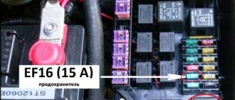
- Contacts or fuse are burnt out.
- Damage or wear of the generator brushes.
- Regulator relay malfunction.
- A break in the stator or rotor circuit due to a short circuit in the winding.
Elimination of the above listed generator malfunctions is solved by replacing worn parts.
How to remove and disassemble the generator. Do-it-yourself generator disassembly.
- Remove the brush holder with the voltage regulator, having first unscrewed all the fasteners.
- Remove the tension bolts and the cover with the stator.
- Disconnect the phase windings from the output wires of the rectifier unit, and then remove the cover from the stator.
- Remove the pulley from the generator shaft and the front cover using a puller.
Generator repair
If the generator winding is shorted or the winding is broken, it is necessary to replace the wires with new ones. Usually the winding breaks in close proximity to the slip rings
Pay attention to the ends of the winding to see if any desoldering has occurred. To eliminate this malfunction, it is enough to rewind the turn in the area of the break back from the rotor winding
Remove the broken end of the winding from the slip ring and solder the unwound wire.
If you find that the alternator is generating a weak or excessive charge, this is a sign of a bad alternator relay. The breakdown can be eliminated by replacing the generator relay. If the generator is working properly and the light is blinking, this indicates a breakdown of the light bulb power diode in the indicator. Such a breakdown can be eliminated by replacing the diode in the generator.
Extraneous noises during generator operation indicate wear of the rotor bearing. The generator should be disassembled, the bearing removed, and inspected for defects. If the alternator bearing is worn, replace it.
To assemble the generator, carry out all steps in the reverse order. You can repair the generator yourself, in your garage, the main thing is to follow safety precautions, be careful with electrical appliances, carefully remember the sequence of disassembling the generator, so as not to sit for a long time on its assembly.
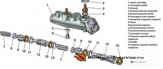
Generator device VAZ 2101, VAZ 2102, VAZ 2104, VAZ 2105, VAZ 2106, VAZ 2107, VAZ 2108, VAZ 2109, VAZ 2110
1 – “negative” brush; 2 – brush holder; 3 – “positive” brush; 4 – neutral wire plug block; 5 – insulating bushings of the contact bolt; 6 – rectifier block; 7 – contact bolt; 8 – stator; 9 – rotor; 10 – inner bearing mounting washer; 11 – drive side cover; 12 – fan assembly with pulley; 13 – outer bearing mounting washer; 14 – front rotor bearing; 15 – spacer ring; 16 – coupling bolt; 17 – clamping sleeve; 18 – cover from the side of the slip rings; 19 – buffer sleeve; 20 – bushing
Checking the field windings
To check the serviceability of the field windings of a car generator, you must first remove the regulator and brush holder to gain access to the slip rings. For diagnostics, you will need an ohmmeter, the probes of which should be applied to the slip rings of the generator. As a result of the test, the resistance should be at a level of 5-10 ohms. You also need to make sure visually that there are no breaks in the winding.
To diagnose a short circuit of the excitation winding to ground, you will need to connect one ohmmeter probe to any slip ring, and attach the second to the generator stator. As a result of the measurement, infinite resistance should be displayed on the screen.
When diagnosing a generator, it is also necessary to inspect it for mechanical damage. Based on the results of all checks, the feasibility of repairing the device or replacing it with a new one is determined.
What to consider when choosing a new battery
According to the passport, the battery is designed for 3-5 years of active use (in reality it turns out to be less). Therefore, over time, it becomes necessary to buy and connect a VAZ 2107 battery instead of a failed one.
When purchasing a new battery, you should consider a number of parameters and characteristics. Battery type: serviced and maintenance-free. The first option allows you to check and replenish the electrolyte level. This makes it possible to use the battery longer.
The next question is: what power will the battery on the VAZ 2107 be most efficient. Batteries with a capacity of 50–60 Ah are suitable for this model. However, given that modern cars are equipped with energy-intensive equipment, it is better to opt for more capacious batteries. In addition, carburetor VAZ models require more powerful batteries - they consume more energy when starting. In terms of dimensions, the VAZ 2107 requires power supplies with dimensions of 242*175*190 mm. The vast majority of samples available on the market fit them.
When choosing a battery, you should also take into account the place of residence of the owner of the “Seven”. For those who live in the south, you can purchase a less powerful battery. Northerners are advised to prefer a battery with a higher capacity: in the cold, the car starts with high energy consumption.
Malfunctions
The main malfunctions of the VAZ 2107 generator include:
- brush wear;
- failure of the diode bridge (rectifier unit);
- failure of rotor bearings;
- short circuit in the excitation winding;
- break or short circuit in the stator winding.
Signs of a faulty generator are:
- no indicator light on the dashboard comes on;
- the voltmeter needle is in the red zone;
- sparking inside the generator;
- noise during operation (hum or howl);
- smoke and burning smell coming from the generator.
Do I need to change the generator?
It is quite difficult to determine the cause of generator failure without having a clue about electrical engineering, so in order to repair it, it is better to contact specialists. Most often, in VAZ 2107 cars, the generator fails due to brush wear, which occurs due to an expended resource or mechanical damage to the commutator. In addition, a short circuit or open circuit in the rectifier often occurs, which is “treated” by replacing the diode bridge.
The hum or howl of the generator indicates bearing failure, which can also be repaired. But if suddenly a short circuit occurs in one of the windings, you will have to either negotiate with home-grown specialists about winding a new winding, which is quite risky, or replace the generator with a new one. The last option would be most appropriate here, especially if it also comes with a guarantee.
A new generator, depending on the model and manufacturer, can cost from 2800 to 5000 rubles. Replacing it at a service station will cost about 500 rubles.
The catalog number of the standard VAZ generator for the “seven” is 21083701010.
Electrical repair
First, the generator must be removed. Before disconnecting the wiring, carefully sketch or photograph the connection diagram. Place the unit on a clean surface so that no debris can get inside. How to connect a generator in the field:
Disconnect the voltage regulator and diode bridge board. Test the diodes and connecting buses with a tester. Faulty radio components are usually visible without measurement. Their repair is impossible, only replacement. Inspect the rotor current collector tracks. The copper surface must be free of oxide deposits, cracks and other damage. If necessary, you can clean it with fine sandpaper.
Differences in the repair of carburetor and injection versions
From a repair point of view, the carburetor and injection versions of the VAZ 2104 engine differ in that:
- a carburetor engine is easier to repair in the field, but it breaks down more often;
- The VAZ 2104 injection engine fails less often, but it is more difficult to repair without the appropriate infrastructure.
The carburetor engine of the VAZ 2104 has a device that has been familiar to consumers of domestic automotive products since pre-war times. The air-fuel mixture is prepared in the carburetor, enters the engine cylinder, ignites from the spark plug and pushes the piston. If the VAZ 2104 engine stalls while driving, if the idle speed fluctuates, if the engine reacts sluggishly to pressing the accelerator pedal, there is only one recipe. I pulled the suction towards myself and off to repairs. Gasoline consumption will increase, but you will get to the nearest auto repair shop in a VAZ 2104 with a carburetor engine.
When an engine with multiport injection needs to be repaired, things are not so simple. The operating modes of the injection engine are controlled by the electronic control unit (ECU). To understand what exactly the fault is that requires repair, you need computer diagnostics, reading error codes from the computer. This is not the case on the road. Get the cable, ask for a trailer or call a tow truck.
Both versions of the VAZ 2104 engine have pros and cons. The trend in the global automobile industry is the transition from carburetor to injection engines. Our time is the time of the injector. So, compared to a carburetor engine, an injection engine has more advantages than disadvantages. And it's not just a matter of repairs.
Injection engines are more economical, reliable and environmentally friendly.