The VAZ 2110 is equipped with a mechanical, two-shaft, five forward gears and one rear gearbox. It is structurally combined with the differential and main gear. The service life of the VAZ 2110 gearbox and its performance directly depend on driving style and timely maintenance of the manual gearbox.
Frequent intense acceleration, incorrect shifting of the selector lever, untimely replacement of transmission oil, and the gearbox oil needs to be changed every 75,000 km , lowering its level can greatly reduce the service life of the gearbox. Removal of the VAZ 2110 gearbox and subsequent repair or replacement is carried out if faults are detected in the unit itself.
Replacing the gearbox of a VAZ 2110, 2112 gearbox. Photo and video instructions
Today we are undergoing repairs on a VAZ 2110, manufactured in 2004, 1.5 16 valve engine, mileage 176 thousand kilometers, the gearbox needs to be replaced. We will show you detailed photos and video instructions on how to do it yourself. The manual is also suitable for VAZ 2112, VAZ 2111, Priora cars.
At first, the owner wanted to repair the gearbox, but then after making approximate calculations, it became clear that it would be cheaper to replace it. A problem with the gearbox knocks out first, second, fifth and reverse gears. We open the hood, remove the plastic cover from the engine, unscrew the clamps from the air filter housing, remove the mass air flow sensor connector, remove the terminals from the battery and remove the battery itself.
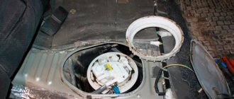
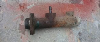
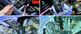
We remove the clutch cable and disconnect the wiring from the starter:
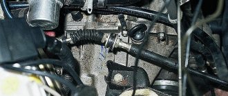
To avoid breaking it, unscrew the speed sensor. To secure the engine, install a transverse crossbar:
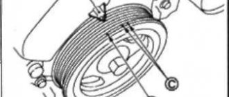
Using a 30mm socket, unscrew the drive nut:
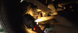
We unscrew the ball joint, there are two 17mm bolts from below. On one side we unscrew the so-called saber (traverse), because the gearbox will rest on it and it will be inconvenient to work with the gearbox. Before pulling out the drive, drain the oil from the box:
Remove the lower arm and remove the yoke:
We take the assembly and pull out the drive, but before that we tighten the drain plug.
We proceed in a similar way on the second side. Unscrew the slide:
After this, unscrew the gearbox mounting nuts:
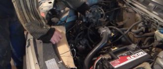
All we have to do is unscrew the cushion nut so that the box does not fall, install the hydraulic strut, in your case you will most likely have to look for helpers who will hold it.
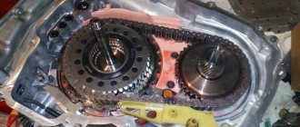
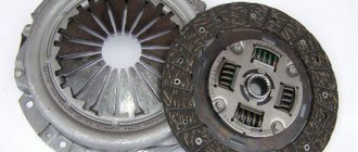
After this, the box can be removed and replaced with a new starter and release bearing. Be sure to check the condition of the clutch; if it needs to be changed soon, it is better to do it now, while the gearbox is removed.
When installing the new box, I had to turn the crankshaft a little, since the input shaft did not fit into it. We look from above so that no wiring accidentally gets between the gearbox and the engine. The entire process of installing a new gearbox is shown in the video step by step. After the replacement, be sure to check how all gears shift.
In what cases should the gearbox be removed?
Before removing the gearbox, you should make sure that the malfunctions are related specifically to it and are not caused, for example, by insufficient oil level, loose gearbox mounts, or defects in the clutch release drive.
Gearbox VAZ 2110
The need to remove the gearbox occurs when the following malfunctions occur:
- transmissions switch off spontaneously;
- unclear gear shifting;
- increased noise, appearance of extraneous sounds;
- when overtaking, the clutch disappears;
- gears are difficult to shift;
- oil leaks.
In addition, the gearbox should be removed in the following cases:
- when replacing the clutch;
- when replacing an old gearbox with a new one;
- if it is necessary to eliminate the leak of the crankshaft rear oil seal;
- when replacing the front gearbox oil seal;
- when replacing the release bearing;
- when replacing the flywheel;
- when replacing the bushing;
- in cases where the box interferes with any repair work.
The weight of the box without oil is approximately 30 kg, so it is recommended to carry out the procedure for removing it with an assistant. It is advisable that he has experience in auto repair work.
Examination
VAZ 2110 replacing box bearings
A possible malfunction can be considered a low oil level. At such moments, not only do the bearings stop functioning correctly, but every part of the gearbox begins to adhere poorly. If you do not fill in the required amount of oil or transmission fluid in time, the parts will quickly wear out. The car is installed above the inspection hole. A thorough inspection is carried out at the time of checking for oil leaks.
So:
With the clutch depressed (see Repairing the VAZ 2110 clutch - we do it ourselves), you need to gradually shift all gears. Their accuracy of operation is checked at the time of switching on and off. If necessary, the gear shift mechanism is adjusted.
Replacing bearings in the box of a VAZ 2110 input shaft
- When the transmission lever is in neutral, the engine must be started. When you press the clutch pedal, you must try to hear the operation of the gearbox bearings. The characteristic sound of a breakdown appears the moment the pedal is released. As soon as you press, the sound disappears again. If the sound is loud, the bearings should be replaced.
- The operation of the gearbox is also checked while the vehicle is moving. It is necessary to accelerate the car, then slow braking. Gears shift up and then down. Here you should check the operation of the synchronizers and the clarity of the gear shift. There should be no extraneous sounds when the gearbox is operating. If the load increases, you must ensure that gears are not changed randomly.
How to remove and install the gearbox on a VAZ 2110 yourself (instructions)
Removing and installing the gearbox on a VAZ 2110 must be done with a partner. Procedure for removing the gearbox Remove the battery The clutch cable must be disconnected from the clutch release fork and removed from the bracket on the gearbox itself
Next, you need to disconnect the electrical harness connector from the speed sensor. Compress the spring and disconnect the connector
VAZ 2110 gearbox itself . Then the next 2 and 3 are used to attach the gearbox to the car engine
At the bottom of the box there is another connector for connecting to the reverse sensor. It also needs to be disconnected
Then you need to unscrew the two bolts securing the torque rod to the gearbox
We loosen the tightening of the clamp securing the gear shift rod and then disconnect it from the gear selection rod hinge by moving it back.
Then we remove the wheel drives and instead of one drive we insert a plug, which we will tie with wire or rope so that it does not fly out when removing the VAZ 2110 box . It is not necessary to completely remove the right drive; you can move it to the side and hang it.
To make it easier to remove the gearbox, I recommend loosening the two bolts securing the ball joint to the steering knuckle
Unscrew the nut of the lower right mounting of gearbox 1 to the engine. Please note that on models with a fuel injection system, a support bracket 2 for the intake pipe is installed under this nut, which must be removed from the stud.
If necessary, you can loosen the bracket fastening nut indicated by the arrow.
Then you need to unscrew the nuts indicated in the lower figure, then remove the cover (1 clutch) and (2 crankcases)
After this, unscrew the bolt of the lower left mounting of the gearbox to the engine
We hang up the engine. For this procedure we use a hoist or board
From the bottom of the car, unscrew the nut securing the left power unit support.
Unscrew the two nuts securing the rear power unit mount to the body.
Unscrew the two bolts securing the rear support of the power unit to the gearbox, holding the nuts from turning with a second wrench, and remove the support.
By inserting a screwdriver between the clutch housing and the cylinder block, slide the gearbox off the guide bushings. Be sure to hold it
Move the gearbox as far back as possible, passing the rear cover of the box over the front suspension brace (the input shaft should disengage from the clutch). If the input shaft cannot be disengaged from the clutch, push the engine to the side. Lower the front end of the box and remove it from under the car.
Install the gearbox in the reverse order of removal.
selection of differential bearing adjusting ring
Differential bearings must be mounted with a preload of 0.25 mm (for control 0.15-0.35 mm). The tension is ensured by selecting the thickness of the adjusting ring 13 (see Fig. 3-7), installed in the gearbox housing socket under the outer ring of the differential bearing.
Note. Select the thickness of the adjusting ring when replacing one of the following parts: differential box, differential bearing and clutch or gearbox housings.
Determine the thickness of the adjusting ring using tool 67.7824.9517 in the following sequence: press the outer ring of the tapered roller bearing 3 together with the adjusting ring 4 (Fig. 3-24) into the gearbox housing;
Note. The installation ring 4 has a constant thickness of 1.25 mm.
Press the outer race of the other differential bearing into the clutch housing. At the same time, be careful not to mix up the outer rings of the differential bearings; install the differential into the gearbox housing and, covering it with the clutch housing, tighten at least three nuts, equidistant from each other, securing the gearbox housing to the clutch housing (tightening torque 24.5 Nm (2.5 kgcm)). Then turn the differential to self-install the bearings 2-3 turns; install support mandrel 2 on the differential box and secure indicator 1 with extension using a universal holder. Install the indicator leg on the support mandrel with a preload of 1 mm, and in this position fix the indicator and set its arrow to zero; move the differential from below and watch the indicator;
WARNING When measuring the axial movement of the differential, do not rotate it so as not to distort the measurement results.
Using the formula S = A + B + C, calculate the thickness of the adjusting ring of the differential bearings, where: S is the thickness of the adjusting ring;
A is the amount of axial movement of the differential; B - the amount of preload of the differential bearings; C is the thickness of the installation ring (constant value). Example.
The indicator reading when moving the differential is 1.00 mm. The preload of the differential bearings is 0.25 mm, the thickness of the mounting ring is 1.25 mm. S = 1.00+ 0.25+ 1.25 = 2.50 mm. After determining the thickness of the adjusting ring, disconnect the clutch housing and gearbox, remove the differential, press out the outer bearing ring from the gearbox housing using a puller 67.7801.9526 and install the selected adjusting ring instead of the adjusting ring 4. Press in the outer ring of the differential bearing using the mandrel 67.7853.9575 and install the differential into the gearbox housing and, covering it with the clutch housing, tighten the nuts securing the gearbox to the clutch housing. Check the moment of resistance to rotation of the differential with a dynamometer 02.7812.9501. To do this, pass the tip of the dynamometer through the hole in the differential box (for the wheel drive shaft) until it wraps around the pinion axis. Turn the dynamometer handle several turns clockwise and use the scale to determine the moment of resistance to turning. It should be: for new bearings 147-343 Ncm (15-35 kgf.cm), for run-in bearings at least 30 Ncm (3 kgf.cm).
Rice. 3-24. Scheme for selecting the thickness of the differential bearing adjusting ring: 1 - indicator; 2 - support mandrel; 3 — differential bearing; 4 — installation ring; 5 - mandrel
Something bad happened and a VAZ 2110 gearbox needed to be repaired. Unit repair is required when:
- It is difficult to switch gears off and on.
- automatic switching off of gears.
- noise occurs when shifting gears.
- transmission oil leak.
The reasons for the breakdown may be different, perhaps the oil was not changed in a timely manner or the mechanism has simply exhausted its resource.
How is a VAZ 2110 gearbox repaired? Do-it-yourself VAZ 2110 gearbox repair, video.
Instructions for removing the gearbox
The procedure for removing the gearbox is labor-intensive and time-consuming. It’s easier to replace it with a VAZ 2110 by visiting a car service center, but you can do it yourself.
Tools
To carry out the procedure, you will need tools consisting of:
- a set of wrenches, socket or open-end wrenches;
- set of heads with extensions;
- flat screwdriver;
- mounts;
- pliers;
- jack;
- clean rags.
In addition, you should prepare a container to drain the used oil. You can use a plastic 5 liter bottle.
Tools should be prepared in advance so that they are nearby while working.
Sequencing
To remove the gearbox, you need access to the underbody of the car, so it needs to be lifted. This can be done using a lift, or driving the car onto an overpass or inspection groove.
Since the removal work is quite complicated, you will need an assistant.
The following video demonstrates replacing the clutch, the first step of which is removing the gearbox.
Do-it-yourself instructions for replacing (removing and installing) VAZ 2110,2112 gearbox
If the transmission is removed in order to repair the clutch, release bearing or flywheel, then it is not necessary to drain the transmission oil and pull the drive out of it.
It is necessary to remove the gearbox on a VAZ 2110 with an assistant. Procedure: 1.Remove the starter, battery and drain the oil. 2. Disconnect the clutch cable from the release fork. To do this, loosen the tightening of nuts 1 and 2, then remove it.
3. Slide the cover off the cable sheath and unscrew the fastening nut. Remove the cable from the bracket on the gearbox. 4. Disconnect the wires from the speed sensor. You need to compress the spring clips. 5. Unscrew bolt 1, which secures the ignition bracket to the VAZ 2110 gearbox, and two bolts 2 and 3, which secure the box to the engine. 6.You also need to disconnect the reverse sensor connector; it is located at the bottom of the car. 7. Unscrew the bolts securing the jet rod to the gearbox, there are two of them. 8. Loosen the bolt of the gear shift rod clamp and disconnect it from the rod hinge, while it needs to be moved back. 9.The next step is to remove the wheel drives; instead of the left one, we put a plug, which can serve as an old CV joint, and tie it so that it does not fall out. It is not necessary to remove the right drive; you can disconnect it from the gearbox, take it to the side and hang it from the body. 10.To make it easier to remove the gearbox on a VAZ 2110,2112, unscrew the left ball joint from the steering knuckle. 11.Unscrew the lower right mount of the gearbox. You should know that on engines with an injection system, a support bracket 2 is installed, which we remove from the stud. 12.If necessary, unscrew the top nut of this bracket. 13. Unscrew the bolts securing cover 1 from clutch housing 2, there are only three of them. 14.Next, you need to unscrew the bolt of the lower left fastening of the VAZ 2110 gearbox to the engine. 15.We hang the engine as follows: install a board on the front fenders, placing rags under it, as shown in the photo below. 16. We tie the power unit to it using a strong rope, cable or, as in the photo, using an old seat belt. The ropes must be in tension. 17.Unscrew the nut securing the left engine mount from the bottom of the car. 18.Then you need to unscrew the two nuts of the rear support of the power unit. 19. We unscrew the fastening of the rear engine mount to the VAZ 2110, 2112 gearbox, while using another wrench we hold the nuts from turning and remove it. 20.Insert a pry bar or screwdriver between the cylinder block and the clutch housing, slide the gearbox off the guide bushings, supporting it. 21. We move the VAZ 2110, 2112 gearbox as far as possible to the left side of the car, passing the rear cover over the stretcher, and the input shaft will disengage. If the shaft does not come out, then push the engine in the opposite direction from the box. As soon as the shaft is disengaged, the box can be removed from under the car. 22.Reinstalling the gearbox is done in the reverse order. 23.Then we install the drive wheels. 24. Fill in the transmission oil, if drained. 25.Then follows the adjustment of the clutch release drive. 26.Adjusting the gear shift lever.
Disassembling and assembling the synchronizer
Synchronizers of 1st–2nd, 3rd–4th and 5th gears are disassembled and assembled in the same way. We show the disassembly and assembly of a synchronizer using the example of a 5th gear synchronizer. Before disassembling, we mark the blocking rings and their position relative to the synchronizer clutch. Remove the blocking rings. We mark the position of the hub relative to the coupling and the position of the crackers relative to the grooves of the hub, so that during subsequent assembly they will be installed in their original places.
To disassemble the synchronizer...
...carefully slide the coupling along the hub, holding the balls with your hand to prevent them from “shooting out”.
5th gear synchronizer parts
:
1 - coupling;
2 - ball;
3 - cracker;
4 - spring;
5 — hub Before assembly, inspect the synchronizer parts. Nicks and chips on the splines of the hub and coupling, the gear rims of the locking rings and the coupling are unacceptable. We replace defective parts with new ones. If there is significant wear on the working conical surface of the blocking ring (the minimum permissible axial clearance between the ends of the gear rims of the gear and the blocking ring is 0.6 mm), it must be replaced.
For ease of assembly of the synchronizer, generously lubricate the springs, crackers and balls with grease.
Putting the hub on the workbench...
...we insert springs into the hub sockets, and crackers into the grooves (in accordance with the previously applied marks). We insert the assembled hub into the coupling, orienting it so that when the ball is subsequently installed...
... it was located exactly in the middle part of the coupling groove - in its deepest place.
Place balls in the holes of the crackers...
...and, pressing each ball in turn with a screwdriver... ...we push the hub along the splines of the coupling.
When installing a synchronizing shaft on the synchronizing shaft, the grooves on the coupling and hub must face:
— for the synchronizer of 1st–2nd gears — to the 1st gear gear;
— for the 3rd–4th gear synchronizer — to the 3rd gear gear;
- for the 5th gear synchronizer - to the thrust plate of the shaft bearings.
Grooves on the clutch and synchronizer hub