The manufacturer assigns a unique number to the vehicle in advance. A 17-digit image (VIN code) is applied to an integral part of the vehicle or a special plate. The VIN code is also entered in the technical passport.
Each Lada Vesta model has an identification number. The VIN code for a Lada vesta allows you to avoid troubles when buying a used car, that is, you can be sure that the car is not listed as stolen and is not pawned.
There are no uniform standards for applying a VIN code. One manufacturer indicates it on a metal plate, another - near the steering wheel or driver's seat. We will look at the principle of composing wine and the method of applying it to AVTOVAZ cars. We will also indicate what to do with the identification number of the owner of Lada vesta and other models in case of loss of the duplicate plate. Read the article to protect yourself and know the meaning of the sign!
Checklist: decoding Vesta's Vin code information
The vehicle's VIN includes information about the country of manufacture, production date, body type, plant, box and other information about the vehicle. The VINs of Lada vesta cars, in particular the Lada model, are located on metal plates. So, how to decrypt VIN-Lada 2180? Let's say you are the owner of a car XTA GFL110 G Y000000
1) The first 3 digits are the international code of the manufacturer, for example AvtoVAZ;
2) 4 and 5 digits are the model number, i.e. GF means the Vesta number;
3) 6 digit L means body: L is a sedan, K is a station wagon, and B is a hatchback, which does not exist yet;
4) digit 7 is the engine code: 1 - 21129, 2 - 11189, 3 - 21179, 4 - h4m Renoshny. Vesta CNG is designated by the letter A
5) number 8 is a box: 1 manual from VAZ, 2 robot, 3 manual transmission Renault;
6) digit 9 is always 0;
7) 10th digit is the year of manufacture: 2015 - F, 2016-G, 2017-H, 2022 -J, 2019-K, 2020-L, 2021-M, 2022-N;
11 sign is the plant Y - means Izhevsk, 0 - Tolyatti;
9) digits 12 to 17 are the serial number.
Examples: GFL11 - Vesta sedan, with engine 21129 manual;
Vesta gfl 33 - Sedan 21179 1.8 liter with gearbox from Renault.
The specified decoding principle is suitable for all sedans, station wagons and gas cars Lada 2180, including gfl11 51 9t9, gfl11-52-X00, Lada gfl110, Lada gfl12 51 9t9 and Vesta gfl12 51 000.
Lada Vesta – engine number 1.6, 1.8
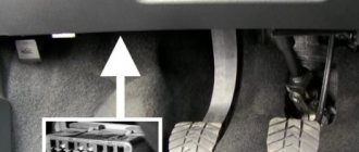
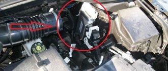
For those who have already closely interacted with Lada cars before, there will also be no difficulties in finding the Vesta engine number, be it a 1.6 (VAZ-21129) or 1.8 (VAZ-21179) engine. The marking is located on the left (in the direction of travel) area of the cylinder block, directly above the connector with the gearbox. You can check the symbols using an inspection mirror with a flashlight, or you can take a photo on your phone by holding your hand from the side of the engine shield:
However, to study the engine number in detail, you will have to dismantle part of the intake line, namely the air filter housing.
Source
What to do if the Lada Vesta VIN plate is lost due to an accident or repair?
It is important to have a VIN plate at the time of sale and purchase. If the marked plate is attached incorrectly (not as intended by the manufacturer), then registration occurs on the basis of the main marking of the vehicle. A corresponding note is made in the technical passport (that the plate is attached using a homemade method). The plate may be lost or damaged during an accident or repair. For example, a blow to the side of a Vesta car damages the B-pillar. There is a possibility that the sign that was under it cannot be restored.
The traffic police representative, who will register the car, will examine the wine under the hood of the Lada 2180. If he expresses doubts about its authenticity, the car owner will have to do an examination. Then check the numbers on the plate again.
Lada Vesta – VIN location and engine number MARKING
Domestic cars have long been leaders in the statistics regarding the number of thefts. Today, although the Lada Vesta lags behind its “Korean” rivals in this regard, it often falls into the hands of car thieves. When choosing a used car, the likelihood of stumbling upon a Vesta with a criminal past is quite high, especially if you consider the price “bottom” of the market.
In order to successfully verify the license plates on the car you are purchasing, you will have to study the location and appearance of all identification marks. Lada Vesta doesn’t have many of them and usually there are no problems finding them.
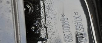
Vesta hides the main VIN number behind the right front door, located right on the central pillar in this unusual position for most cars:
The symbols are machined with a hard low-carbon needle with appropriate processing marks
A sticker with a duplicate VIN is nestled in close proximity and look how much it resembles plates from Renault:
What is the use of a VIN code?
This convenient form of identification was invented in the United States of America back in the 1970s. Widespread use began only in the late 80s. As was said, there are no uniform design rules. But manufacturers are required to adhere to a certain international standard when producing cars for export. The standard is designed so that the number is unique.
The convenience of a VIN plate is undeniable: it allows you to reliably determine when purchasing whether the car has been pledged or stolen from its rightful owner.
Where are the numbers
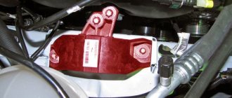
The VIN code of the Lada Vesta car is stamped on the middle pillar of the car on the right side (passenger side). The VIN code is also duplicated on the wall between the engine compartment and the engine.
Explanation of the marking table, which is located on the right pillar, below, near the threshold:
Let us recall that in accordance with the Decision of the Customs Union Commission dated June 15, 2011 No. 711, the model year is defined as a conditional year indicated by the manufacturer (usually following the actual year of manufacture of the vehicle).
At JSC AVTOVAZ, the start of the model year is set on July 1 of the calendar year. Thus, from January 1 to June 30, the model year corresponds to the actual year of manufacture of the car, and from July 1 to December 31 corresponds to the one following the actual year of manufacture of the car.
The model and engine number of VAZ 21129 are stamped on the end of the cylinder block on the left next to the gearbox.
Interior and cabin equipment
| Lada Vesta models | Standard | Classic | Comfort | Luxe | Exclusive |
| Rear seat headrests | + | + | + | + | + |
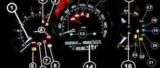
| On-board computer | + | + | + | + | + |
| Current gear indicator | + | + | + | + | + |
| Rear seat with folding backrest | + | + | + | + | + |
| Fabric seat upholstery | + | + | + | + | + |
| 12V socket | + | + | + | + | + |
| Adjustable steering column | + | + | + | + | + |
| Cabin air filter | + | + | + | + | + |
| Light window tinting | + | — | — | + | + |
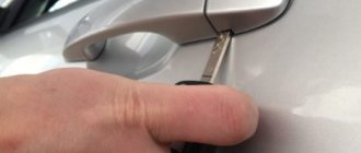
| Folding key | + | + | + | ||
| Central locking with remote control | + | + | + | + | + |
| Electr. front door power windows | + | + | + | + | + |
| Audio preparation | + | + | + | — | — |
H4Mk (HR16) engine disassembly
Engine Identification Data
The engine identification data is as follows:
Explanations of marking (A) are given in Figure 2.
Explanations of marking (B) are given in Figure 3.
Engine specifications are shown in Table 1.
Cylinder diameter, mm
Install the engine on a stand for disassembling and assembling units.
Unscrew the oil drain plug, drain the oil from the engine and tighten the plug (head 15).
Loosen the bolts 1, Figure 4, of the water pump pulley, blocking the water pump pulley with a screwdriver.
Remove the accessory drive belt.
Unscrew the bolts securing the water pump pulley, holding the pulley with a screwdriver, and remove the pulley (flat screwdriver, 10mm head).
Disconnect the heating hoses (pliers) from the throttle pipe.
Disconnect the throttle pipe heating hoses from the coolant outlet pipe and remove the hoses from the engine (pliers).
Remove the crankcase ventilation tube (pliers).
Remove the intake module assembly with the throttle pipe and gaskets (head “10”, extended).
Remove the wiring harness mounting bracket (head “8”).
Remove the fuel rail protective screen (replaceable heads 8, 10, extension).
Disconnect the ignition coil wiring harness connectors from the ignition coils.
Disconnect the injector wiring harness connectors from the fuel injectors and remove the harness from the engine.
Remove the fuel rail with injector assembly (head “10”, extended).
Remove the ignition coils ("8" head, knob and extension).
Remove the spark plugs (spark plug key 14).
Unscrew the fastening bolt and remove the phase sensor (10mm head, knob and extension).
Unscrew the fastening bolt and remove the solenoid valve of the phase regulator (head “8”, knob and extension).
Remove the oil level indicator tube (grab grip (pins)).
Unscrew the fastening bolts and remove the cylinder head cover ("8" head, knob and extension).
Turn the crankshaft clockwise until mark 1, Figure 5, of the crankshaft pulley and mark 2 on the timing cover are aligned. In this case, the marks of the camshaft phase regulator 1 and the exhaust camshaft sprocket 2 are located as shown in Figure 6. Otherwise, turn the crankshaft one more revolution until the marks on the crankshaft pulley and on the timing cover align.
Install the flywheel retainer 1, Figure 7 (flywheel retainer 67.7820-9708 or 00 00 143 100).
Unscrew the fastening bolt and remove the crankshaft pulley (head 19).
Remove the crankshaft front oil seal as shown in Figure 8 (flat head screwdriver, wood or plywood thrust plate).
Unscrew the mounting bolts and remove the flywheel and flywheel retainer (TORX E20 head).
Remove the crankshaft rear oil seal as shown in Figure 9 (flat head screwdriver).
Unscrew the timing cover bolts (replaceable heads 8, 10, 13).
Carefully remove the timing cover as shown in Figure 10.
Disconnect the timing cover, as shown in Figure 11, remove the cover (tool 67.7812-9712 for removing the crankcase or 77 11 381 716, hammer with plastic striker).
Check the position of links 1, Figure 12, of the timing chain relative to marks 2 on the crankshaft sprocket, camshaft sprocket and phase regulator. The difference in the position of the chain links relative to all three marks should be the same.
Press the chain tensioner plunger into the tensioner body by pressing shoe 1, Figure 13.
Fix the plunger by installing a piece of steel wire 2 with a diameter of 2.5 mm into the hole in the tensioner body.
Unscrew the tensioner mounting bolts and remove the tensioner, not allowing the plunger to become loose (the “8” head).
Remove the timing chain tensioner shoe.
Unscrew the fastening bolts and remove the timing chain guide (head “10”).
Remove the timing chain from the engine.
Turn tensioner 1, Figure 14, of the oil pump drive chain counterclockwise.
Remove the oil pump drive chain tensioner from the shaft and tensioner spring 2 from the cylinder block.
Unscrew nut 1, Figure 15, oil pump drive sprockets (ring wrench 10, TORX E8 head).
Remove oil pump drive sprocket 2 with pump chain 3 assembly.
Remove the crankshaft sprocket (universal puller).
Unscrew the three mounting bolts and remove the oil pump from the cylinder block (10mm head, knob and extension).
Unscrew the four bolts securing the water pump, remove the water pump and gasket ("10" head).
Unscrew the two bolts securing the generator and remove the generator from the engine (head “10”).
Unscrew the three bolts securing the air conditioning compressor and remove the compressor from the engine ("10" socket).
Unscrew the four bolts securing the bracket for auxiliary units and remove the bracket (head “10”).
Unscrew two bolts 1, Figure 16, securing the thermostat cover, remove the clip securing the oil level indicator tube, thermostat cover 2 and remove the thermostat valve from the cylinder block (head “12”, knob and extension).
Unscrew bolt 1, Figure 17, securing the knock sensor and remove sensor 2 (head “10”).
Unscrew oil pressure sensor 3 from the cylinder block (ring wrench 22).
Remove oil filter 1 from the engine, Figure 18 (chain or belt wrench for removing the oil filter).
Unscrew the coolant temperature sensor from the coolant outlet pipe (ring wrench 19).
Unscrew the seven bolts securing the coolant outlet pipe, remove the pipe and gasket (10mm head, knob and extension).
Unscrew the bolt securing the crankshaft position sensor and remove the sensor (10mm socket, knob and extension).
Unscrew the bolts securing the screen of the thermal protective upper exhaust manifold and remove the screen (10mm head, knob and extension).
Unscrew the oxygen sensor from the exhaust manifold (ring wrench 22).
Unscrew the five nuts securing the exhaust manifold, remove the manifold and gasket (10mm head, knob and extension).
Unscrew the bolts securing the screen of the heat-protective lower exhaust manifold and disconnect the screen from the manifold (10mm head, knob and extension).
Unscrew the bolts securing the phase regulator and the camshaft sprockets, holding the camshafts with a wrench, remove the phase regulator 1, Figure 19, and sprocket 2 (wrench 22, socket “13”, wrench and extension).
Unscrew the nineteen bolts securing the camshaft bearing caps and remove the caps (head “8”).
Remove the camshafts.
Unscrew the ten bolts securing the cylinder head, remove the washers, cylinder head and gasket (10mm socket head, wrench and extension).
Unscrew the eight bolts securing the oil sump cover and remove the cover 1, Figure 20 (head “8”, extension, tool 67.7812-9712 for removing the crankcase or 77 11 381 716, hammer with a plastic striker).
Unscrew the ten bolts securing the cylinder block amplifier (10mm head, knob and extension).
Carefully separate the cylinder block amplifier using a screwdriver, as shown in Figure 21a, at points 1 and 2, Figure 216 (flat screwdriver).
Remove booster 1, Figure 22, from the cylinder block using tool 2 (tool 67.7812-9712 or 77 11 381 716 for removing crankcase, hammer with plastic striker).
Remove the O-ring from the cylinder block.
Unscrew the bolts securing the connecting rod covers, remove the covers (head 11, knob and extension).
Remove the pistons with connecting rods from the cylinder block on the cylinder head installation side.
Attention. When removing the pistons, avoid damaging the lubrication nozzles.
Unscrew the bolts securing the crankshaft main bearing caps, remove the caps, crankshaft and thrust half rings (TORX E14 head, knob and extension).
Note. When removing the thrust half-rings, mark their position relative to the cylinder block in any way that does not lead to damage to the parts.
Unscrew the three bolts securing the crankshaft position disc and remove the disc (TORX T40 head, knob and extension).
Disassembling the cylinder head
Install the cylinder head on the device (device 67.7823-9567 for desiccation and drying of valves).
Remove the valve tappets from the cylinder head, marking their position relative to the cylinder head in any way that does not damage the parts.
Compress the springs of one row of valves and remove the crackers (tweezers).
Remove the valve plates, springs and spring support washers.
Repeat the operations for the second row of valves.
Remove the cylinder head from the tool and remove the valves.
Press out the oil seals (pliers for removing oil seals).
Unscrew the exhaust manifold mounting studs (TORX E8 head).
Remove the centering pins of the cylinder head covers from the cylinder head (pliers).
Unscrew the oil filter of the phase regulator from the cylinder head (head “8” for an internal hexagon, knob and extension).
Why is this information useful?
- When registering a car (the traffic cop will inspect and check the identity of the numbers on the body and in the title)
- To decipher the package (see below).
Decoding the sign
1 - vehicle manufacturer; 2 — vehicle approval number; 3 VIN code; 4 — permissible maximum weight; 5 - maximum permitted weight with trailer; 6 — permissible load on the front axle; 7 — permissible load on the rear axle; 8 - code for spare parts; 9 — engine model; 10 - modification of the car.
Decoding the characters contained in the duplicate table
- Manufacturing company;
- Vehicle type number;
- Identification number (VIN);
- Maximum permissible vehicle weight;
- Maximum permissible weight of a car with a trailer;
- Maximum load on the front axle;
- Rear axle load limit;
- Code for spare parts;
- Engine modification;
- Vehicle equipment.
Unlike many foreign cars, the plate on the Vesta SV Cross does not contain information about the car’s color number.
Security and systems
| Options | Standard | Classic | Comfort | Luxe | Exclusive |
| Driver airbag | + | + | + | + | + |
| Passenger airbag | + | + | + | + | + |
| ISOFIX child seat anchorage | + | + | + | + | + |
| Rear door child lock | + | + | + | + | + |
| Automatic door locking at start | + | + | + | + | + |
| Automatic activation of emergency lights during emergency braking | + | — | — | — | + |
| Automatic door unlocking and hazard warning lights in the event of a collision | + | + | + | + | + |
| Immobilizer | + | + | + | + | + |
| Security alarm | + | — | — | — | + |
| ERA-GLONASS | + | + | + | + | + |
| ABS, EBD | + | + | + | + | + |
| BAS | + | — | + | — | + |
| ESC | + | + | + | + | + |
| TCS | + | + | + | + | + |
| HSA | + | + | + | + | + |
| EUR | + | — | — | — | + |
| Seat belt height adjustment | + | — | — | — | + |