Here I am figuring out how to connect the device from a VAZ2110! First, I scoured the Internet and found the pinout of VDO devices!
1 Brake fluid level lamp. 2 Emergency lamp. 3 High beam lamp. 4 Fuel level indicator. 5 To speed sensor. 6 Check. 7 Brake fluid level lamp. 8 Left turn lamp. 9 Right turn lamp. 10 Instrument lighting. 11 Minus 12 power supply instruments 13 Fuel lamp 14 Minus 15 Low -voltage input of the tachometer we connect to the injector 16 high -voltage input of the tachometer we connect to the coil 17 PLUS PLUS COLLECTION FRIENT 19 LAMP LAMP LAMI LAMP 22 22 go to the brain if the carburetor does not connect 23 instrument power plus 24 Handbrake lamp 25 Battery charge lamp 26 Oil pressure lamp
Now the pinout of Tavria devices
1 Weight minus 2 Gasoline 3 Power plus 4 Long range 5 Brakes 6 Turns 7 Choke 8 Temperature 9 Dimensions 10 Oil 11 Battery 12 Gasoline Then we reconnect everything and everything works smoothly!
Let's be honest - the VAZ 2110 does not have the most beautiful “native” instrument panel, either on the first cars or on the “improved” ones. Therefore, many owners of this model are trying to make it more modern and somehow decorate it (with LEDs, beautiful lights, etc.).
But, before you decide on some kind of upgrade, it is necessary that you have before your eyes the pinout of the instrument panel for the VAZ 2110, otherwise you can simply get lost in a heap of wires, sensors and buttons. Moreover, it will be useful regardless of whether you completely change the panel, or simply make some additions to the dashboard of your VAZ 2110.
Instrument panel VAZ 2110
Connection knowledge
Before starting dismantling work, you need at least a conventional pinout on paper, otherwise it will be very difficult: you will need to “trace” every wire and every connection that is on the “path” from the devices to the power button.
In fact, the pinout of the VAZ 2110 dashboard is not so difficult to understand, but there are differences between cars produced in different years and at different factories. There is an old model, there is one with a mechanical odometer, and a new (Euro) model, so there are differences in the pinout of the instrument panel, depending on the type to which it belongs.
General diagram of devices
If you look from the back of the instrument panel, here it is in sequence - from top to left to right:
- Fuel level indicator;
- Combination of instrument lighting lamps;
- Right turn control;
- Left turn control;
- Tachometer;
- Next is the block, there are a lot of plugs in it;
- And the top part of the dashboard is completed by an antifreeze temperature indicator.
VAZ 2110 dashboard connection diagram
The lower part of the dashboard (also from left to right and from the back of the dashboard). The following part of the instruments is located here:
- high beam controller (bulb);
- alarm controller;
- brake fluid level control lamp;
- speedometer;
- CHECK ENGINE controller;
- battery charge control;
- parking brake controller;
- oil pressure controller;
- air damper controller in the carburetor;
- outdoor lighting controller.
White block
The connector number, wire color and the unit (assembly) to which it goes are located in the white block as follows:
- The first connector has a black wire. Its purpose is the body (mass);
- In the second - red-brown - this is a low-voltage supply from the electronic control unit - tachometer;
- The third, yellow one is also a tachometer, but this is a high-voltage supply from a coil;
- The fourth, red-blue is Const from the battery + 12V, going through the sixth fuse;
- The fifth, green-white - it is intended to indicate the coolant temperature;
- Sixth, green-yellow – for size fuse F1;
- The seventh connector does not have its own color and goes to the “choke”, the throttle valve;
- Eighth, red and white - CHECK ENGINE light;
- In the ninth and tenth there are 2 orange wires each, leading to 2 power fuses F19+12V;
- In the eleventh there are 2 blue-brown wires leading to the “BK” terminal of the parking brake;
- The twelfth, brown-white is the output “D” of the generator;
- Thirteenth, gray and blue – for the oil pressure sensor.
Troubleshooting methods
What are the troubleshooting options:
- If there is no backlight, you need to check the fuse and replace it if it is blown. All failed light bulbs must be replaced.
- If the sensors are not working, you should check the integrity of the wiring with a multimeter or other tester to check the wiring. Damaged sections of wires also need to be replaced.
- If the car interior is humid, over time this can lead to oxidation of the shield contacts. If such a malfunction occurs, the contacts must be cleaned or replaced.
- If the problem lies precisely in the inoperability of the instrument cluster, then it is better to entrust the repair to specialists. It is possible that in the process you will have to resolder some elements, so if you do not have experience in carrying out such events, then contact an electrician (the video was shot by Alexey Lipatov).
Instructions for dismantling the tidy
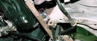
So, how to remove and disassemble the device for its subsequent repair or replacement:
- To begin, you will need to use a Phillips screwdriver to unscrew the two self-tapping screws located on the top trim.
- After this, you also need to unscrew two more bolts, they are located on the bottom of the lining.
- Then you need to carefully detach the cover and put it aside.
- Next, the connectors with wiring from the buttons located on the sides of the device are disconnected. This will allow you to move the trim to the side.
- Only after these steps can you unscrew the two bolts that secure the tidy to the center console. They are located at the ends.
- Then you need to carefully slide the combination back, parallel to disconnecting it from the metal plates installed on top.
- For complete dismantling, you also need to disconnect the two connectors with the wiring on the back of the panel. Having done this, you can remove the device from the mounting location and begin repairing or replacing it. The assembly procedure is carried out in reverse order.
Photo gallery “Removing the tidy with your own hands”
Nuances of work
However, these pinout diagrams for the VAZ 2110 are, so to speak, basic, mostly the same, but there are also differences in color markings (especially by manufacturer). Therefore, you need to either use the instruction manual that came specifically with your car, or, armed with a marker and self-adhesive labels, “write everything out” in detail and not get confused when installing a new instrument panel.
Connecting wires to the VDO panel on a VAZ 2110
Connecting wires to the “Schetmash” panel in Kursk on a VAZ 2110
Connecting wires to the “AP” panel in Vladimir on a VAZ 2110
Connecting wires to the panel from the Kalina car to the VAZ 2110
During subsequent assembly, there will probably be a lot of devices that are not taken into account here, and, taking into account modern realities, many car owners plan to install them on the updated dashboard.
Connecting the trip computer
The mentioned diagram took into account only one, brown wire leading from the red block to the trip computer, but this is clearly not enough. Therefore, let's see how the pinout occurs here.
- The fuel consumption signal from the electronic control unit is indicated by a green wire;
- Orange leads to terminal “15” in the ignition switch;
- Red and white - to terminal “30” in the ignition switch;
- Black, which is common, goes to ground;
- The speed indicator corresponds to brown;
- The positive terminal of the fuel sensor is green and red;
- Responsible for lighting the dashboard white, it leads to the light control.
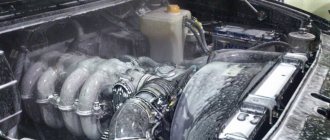
Make sure that the board is not damaged, on which, in fact, uninterrupted reading of information from your VAZ 2110 depends, and providing it to you through all those sensors and devices that you always see in front of you.
Probably, hardly anyone will argue with the fact that the VAZ “ten” is not the pinnacle of design thought. However, there is nothing surprising here, because this car was designed back in the last century. At the same time, the compensator, and quite a serious one, in this case is the price. In other words, a certain compromise is proposed - the imperfection of the car in exchange for an acceptable cost. Well, the choice is ultimately made by the car owner himself, deciding whether this option is suitable for him.
Why you should know the pinout
But before you start this kind of upgrade, you need to understand which wire leads where. The pinout of the instrument panel of a VAZ-2110 car is a very important point when “tuning”. Without this, you risk simply getting confused in a fairly large number of wires, buttons and various sensors. The pinout will be useful in any case - both when making minor improvements and when completely replacing the instrument panel.
The process of installation and dismantling itself is quite labor-intensive, but if you know the correct sequence of actions, then there is nothing particularly difficult about it.
For these works you will need a minimum set of tools - a screwdriver and pliers.
For those who are doing this for the first time, it is best to stock up on self-adhesive pieces of paper, like those on which prices are written in stores, and a pen. With their help, at the time of disassembly, you will indicate, firstly, the sequence of dismantling the parts, and secondly, which wire is connected where. At first glance, this may seem time-consuming, but in fact, for beginners, such markings will help them put the panel back together faster.
At the same time, before starting work, it is best to stock up on a pinout diagram - at least conditional. After all, during the work process you need not to confuse anything and correctly understand each wire and connection during the reassembly process. It is worth noting one very important point. By and large, understanding the pinout of the panel of the “tenth” family will not be difficult even for a beginner.
But you need to remember that there are certain differences here, depending on the plant where the car was manufactured and the year of its manufacture. For example, the instrument panel may be an old model, with a mechanical odometer. If the odometer is electronic, then this is a newer version. Accordingly, there are certain differences in pinout between these panels.
Removal and modification
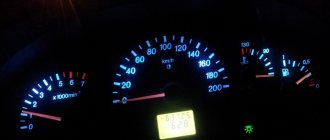
Here's a quick look at the device and control panel icons. If for some reason she refuses, don’t immediately panic. Most often, the reason is the absence of contacts in some place in the wiring. But of course, if you wish, you can completely change or tune the panel.
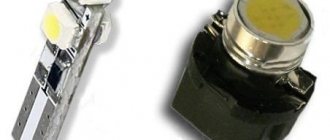
For example, remove the cover and replace the light bulbs with brighter LEDs. Such a panel works brighter and the signals sent by the car will be more noticeable to the driver. If desired, you can install a more solid europanel, which will transform the interior.
- Disconnect the “-” wire from the battery;
- Remove the shield by unscrewing the screws;
- Remove the fastenings of the control panel to the trim, remove the instrument cluster from the socket;
- Remove the glass mask;
- Disconnect the wires from the block;
- Make changes to the instrument panel or replace it with a new one. Reassemble everything in reverse order.
Source
Which wire goes where?
First, let's look at the back of the instrument panel. At the top there are:
- fuel level indicator;
- dashboard lighting lamps;
- control of right and left turns (separately);
- tachometer;
- block with many plugs;
- coolant temperature gauge.
As you can see, there is really nothing particularly complicated here. At the bottom of the instrument panel on the back side there are controllers:
- high beam;
- "emergency lights";
- CHECK ENGINE;
- battery charge;
- parking brake;
- oil pressure;
- air damper (for models with a carburetor);
- outdoor lighting work.
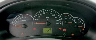
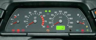
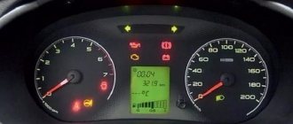
Icons on the dashboard of the VAZ 2110: what do they mean?
Along with the description, all designations require decoding. Knowing the names of the indicators will not provide a complete understanding of the situation. Below, under similar numbers, is the decoding of each sign:
- 3-4 – lamps indicate the turn signals are on;
- 7 – the gas station icon indicates that there are less than 8 liters of fuel left in the tank;
- 8 – symbol confirming the normal operation of the dimensions;
- 9 – exclamation mark indicates incorrect brake operation;
- 10 – dimensions included;
- 13 – emergency stop mode activated;
- 14 – a critical engine failure has been detected, urgent intervention is needed;
- 16 – critical drop in battery charge;
- 17 – handbrake lamp, indicates that the lever is raised;
- 18 – possible oil leakage from the engine crankcase;
- 19 – the symbol indicates the closing of the carburetor damper.
By deciphering the symbols, you can independently determine the essence of the problem and fix the problem.
Features of connecting BC
In conclusion, I would like to dwell in more detail on such a point as installing an on-board computer. In the typical pinout diagram shown just above, there is only one wire leading to it - brown. But for the correct operation of this device, this alone will not be enough. Therefore, here is a complete pinout diagram for connecting the on-board computer:
- Green wire – comes from the electronic control unit, needed to obtain information about fuel consumption.
- Orange – goes to the ignition switch, to terminal 15.
- White-red - in the same place, only to terminal 30.
- The common ground wire is black.
- Brown – needed to take speed data.
- Red-green - to the positive circuit of the fuel level sensor.
- White - leads to the light control, which is responsible for the lamps that illuminate the instrument panel.
Tidy error codes
Standard errors in car self-diagnosis do not accurately indicate a breakdown. Due to the simplicity of the on-board computer, the device can only indicate the direction where to look for the problem. The decoding of standard errors looks like this:
- 0 – no errors detected – the system is in perfect order;
- 1-2 the voltage in the on-board network is exceeded or too low;
- 3 – malfunction of the float sensor in the gas tank;
- 4/5 malfunction in the antifreeze and ambient temperature sensor circuits, respectively;
- 6 – critical overheating of the power plant, it is necessary to wait for the antifreeze to cool down;
- 7 – not enough oil in the engine crankcase;
- 8 – the problem lies in the brake system;
- 9 – the battery is dead or the part is damaged;
- E – error in the firmware, EEPROM data packet is broken.