The fuel injection system is a fairly important part of modern vehicles. Of course, like the rest of the car, it needs maintenance.
The essence of this article is precisely the independent maintenance of injectors, namely the process of flushing without removing them from the engine. You can carry out this procedure yourself, without resorting to expensive services at local service stations.
Do-it-yourself waste oil burner manufacturing features
The easiest way to make a burner is using a small gas cylinder or a blowtorch. To work you need to prepare:
- the above container;
- welding machine;
- grinder;
- a piece of 1.5-inch pipe;
- a round plate equal to the inner diameter of the pipe;
- a piece of wire 6 - 8 mm;
- bolt with a through internal hole for the oil supply nozzle;
- a thick round blank for the lid.
Beginning of work
- Two holes are drilled tangentially in the cylinder: from the bottom (for the mixture of air and oil to enter), and from the top for the flame to exit. Tubes with a diameter of 1.5 inches are welded. One is a continuation of the other, only a little higher; so that the fire swirls inside and does not immediately fly out into the street.
- An ignition hatch is made on top and equipped with a heavy lid so that it does not open during operation due to the pressure of incoming air.
Air flow control
The pressure and amount of air supplied for combustion is regulated by a homemade damper (it is made according to the throttle principle, like in a carburetor).
The flap is installed in the supply pipe upstream of the fuel injector as follows:
- A hole for the rotary axis is drilled strictly according to the diameter of the existing workpiece.
- A round plate is cut along the inner diameter of the pipe, which in the closed position can completely block the hole.
- A rotary axis is made in the shape of the letter “L” and a damper is mounted on it with small bolts.
- In front of the damper, a hole is drilled or a slot is cut in the supply pipe to remove “excess” air (in case there is a lot of it for the burner).
The principle of feeding waste into the burner itself
To supply oil, a diffuser is installed in the intake pipe immediately behind the damper. The diffuser is a chiseled ring insert that slightly narrows the flow area. Thanks to it, a vacuum is created and oil (or other liquid fuel) flows through the nozzle and mixes with air.
For the supply pipeline, it is preferable to use metal pipes. A freon tank is well suited for the fuel tank, and the needle valve allows you to precisely regulate the oil supply.
Simple homemade burner
The oil must be separated from water and filtered.
Principle of operation
The fuel is supplied by gravity to the nozzle and is sucked in by air passing through the diffuser. The resulting mixture ignites inside the cylinder, and the torch is blown outside. Thus, the source of heat is the burner itself (heats up to a crimson glow) and the torch.
The flame can even be used to melt some metals such as copper, aluminum and others that have a lower melting point.
Making a drip heater
Most often, craftsmen use old oxygen and propane cylinders with a diameter of 220 and 300 mm, respectively, to assemble droppers. The former are preferable because of their powerful thick walls that can last a long time and not burn out. A pipe made of low-carbon steel (St 3-10) with a wall thickness of 5 mm or more is also suitable.
Select rolled metal for other parts according to the drawing of the furnace with top feed of waste into the combustion zone. The blower fan is a “snail” from a VAZ 2108 cabin heater or its Chinese equivalent, the fuel line is a stainless tube with a diameter of 8-10 mm.
The manufacturing technology is as follows:
- Make a fire bowl from a piece of pipe or take a ready-made steel container. It must be removed through the inspection hatch, so do not make the tray too large.
- Cut openings in the body for the chimney pipe and cleanout hatch. In the latter, make a frame and install the door (possibly bolted).
- Make an afterburner. Take your time to drill all the holes indicated on the drawing; do the bottom 2 rows first. You will complete the rest while setting up the oven.
- Weld a cover and an air duct with a flange for mounting the fan to the afterburner. Attach the fuel supply device as shown in the photo.
- Assemble the heating unit and connect it to the chimney.
We invite you to familiarize yourself with: What styles of clothing are there for men?
The afterburner in the photo is close-up - side and end views
To regulate the heating power, it is necessary to provide control of the fan speed and a device for dosing the fuel supply (as a rule, an automatic drinker with a jet break is used). According to reviews from craftsmen on a popular forum where heat extraction issues are discussed, fuel consumption in the furnace can be monitored visually. The trend is this: if the oil flows in drops at the break in the stream, then less than 1 liter per hour burns, and when a thin stream flows, more than 1 liter per hour.
Different designs of dropper bowls
Drilling holes
In order for the air flow to atomize the fuel as efficiently as possible, the hole should be as small in diameter as possible. The priority is 0.010 inches. Although holes up to 0.020 in size are also considered acceptable. To obtain them, special thin drills are used. If you look at them from the side, they will seem intermittent. In any case, the drilling process should be done slowly and carefully. Compressed air will flow through these holes.
As for spraying using air, this option is more preferable than gas. This is due to the low cost of the resource. While you have to pay for gas, you don’t have to pay for air. In addition, you need very little of it, so you can use ordinary compressors, such as those used on aquariums. In principle, the Babington burner, the drawings of which you can find in this article, is almost ready for use. There are a few small parts left.
When and for what purpose should the injector be flushed?
Ideally, all injectors of the power unit should produce at the output a high-quality torch of air-fuel mixture of the correct shape. But during the operation of the car, the fuel system becomes contaminated with various impurities. This is often preceded by the use of low-quality fuel, in which additives were used to increase the octane number. It is also possible that water, benzene compounds or sulfur were added to gasoline at gas stations in order to make a profit.
Common contaminants can get into a car's gas tank: dust, rain or rust, which inevitably appears during the process of using the car for its intended purpose. Over time, all this dirt reaches the injectors, settling on them, which causes disturbances in their normal operation. And in such a situation, you will need to flush the injector, which you can do yourself.
Even with a quick inspection during the initial cleaning of the injectors, you can notice that the fuel is pressed through with difficulty and at the exit there is not a normal torch, but several jets intertwined with each other. In such a situation, normal operation of the cylinder is not possible. This is due to the fact that the fuel is supplied either in incomplete volume or does not burn completely. In the latter case, there is a large excess consumption of gasoline. There is only one way out of this situation - flushing the injectors. Today there are several DIY methods for this procedure.
Do it yourself
The process of making a Babington burner is not very complicated and, if you have all the necessary materials and tools, it will only take a few days, depending on the skills of the person.
To manufacture this unit you will need the following materials:
- steel tube DN10,
- metal tee with a diameter of 50 millimeters with internal thread;
- a metal sphere (or hemisphere) with a diameter of less than 50 millimeters;
- copper tube DN10 at least one meter long;
- metal elbow DN10 with external thread;
- a bend with a diameter of 50 millimeters with an external thread, a length of at least 10 centimeters;
You will also need a minimum set of tools:
- angle grinder (grinder) or hacksaw for metal;
- perforator;
- special chuck for thin drills;
- drill;
- drill with a diameter of 0.1–0.3 millimeters;
- soldering iron;
Preparatory stage
Before starting assembly, you need to make a hole in the sphere (hemisphere). This is one of the most difficult and critical stages, since the hole must be made exactly in the middle. Otherwise, the burner torch will be directed to the side, which in turn can negatively affect the quality of the product and its efficiency.
In addition, drilling holes of this diameter is a difficult task, since thin drills can break. Therefore, this process must be carried out carefully and slowly.
Step-by-step instruction
Once the sphere or hemisphere is ready, you can begin assembly. It is very simple and consists of several simple manipulations:
- The metal squeegee will act as a nozzle. It is cut to the required length and screwed into the tee. After this, a hole is drilled in the side of the burner, large enough so that the jet can be ignited through it.
- On top of the tee, closer to the nozzle, a hole is made for a copper tube through which fuel will be supplied to the device.
- An elbow is attached to the copper tube to connect the fuel line.
- A copper tube makes several turns (2-3 will be enough) around the nozzle. They must be done at some distance from the drive. This will allow the oil to be heated to the desired temperature before it hits the sphere.
- In the sphere, at the opposite end of the small hole, another hole is drilled along the outer diameter of the steel tube. The tube is hermetically inserted into the sphere. This is necessary so that the air exits only through a small hole, and pressure is created inside it. If a hemisphere is used instead of a sphere, then the tube is soldered at the small hole and sealed.
- From the opposite end from the nozzle, a metal tube with a sphere is inserted into the tee. She is fixed in it.
- Thus, the burner is ready for use. All that remains is to connect a compressor to the tube with the sphere, which will pump air into it and a fuel line to the copper tube.
- If desired, this system can be improved by connecting a pump to supply oil. You can also install a control unit with control sensors. This will make this system automatic and more secure.
Operating rules
In order for the burner to be safe to operate, all parts associated with the supply of air and waste oil must be sealed. In addition, it is necessary to protect the mining storage from accidental penetration of fire. To do this you need to make an iron screen. It can be similarly made from other fire-resistant materials.
For safety, it is equally important that the torch burns strictly straight (this depends on the accuracy of the placement in the very center of the drilled small hole). Correct adjustment of the oil supply to the burner is also considered very important. It can be accomplished due to the longitudinal displacement of the tube with a sphere (hemisphere) from inside the tee.
Fuel supply
Amateur craftsmen often supply drip furnaces with single-stage fuel: an oil tank, a ball valve, and a supply tube. Firstly, this is dangerous: for convenience and safety of starting the stove, the valve must be placed closer to it. The supply tube gets quite hot when fuel is supplied from the bottom. If the heating passes through the pipe past the valve, up to which there is a solid column of fuel in the pipe, this could lead to disaster. Secondly, the fuel supply to the furnace is unstable: as the tube warms up, the drops become more frequent, because the oil thins out. If it flows in a trickle, then it is again dangerous.
The drip supply of oil to the furnace during processing should be organized according to a 2-stage scheme: main (storage) oil tank - valve - supply dropper - supply tank (tank) - free flow from it at least 60 mm from the bottom (for additional sedimentation of sludge) - working dropper. The fuel supply is opened when the kindling in the bowl (see below) is lit. While the oil drips into the tank to the level of the drain, you can slowly adjust its flow, and then it drips into the bowl drop by drop.
Scheme of safe power supply of a drip furnace from a supply tank with a safety valve and capillary
This system, however, is not completely safe. If in a hurry, out of ignorance, or simply trying to quickly warm up from the cold, open the valve too much, the consumables will immediately fill, fuel will rush into the stove, and it will throw out a tongue of fire and start spitting burning spray. It would be correct to build a drip oil supply system into the furnace with a safety float valve and a metering capillary (see figure on the right).
Since different metals are wetted by waste in different ways, and its properties vary significantly from batch to batch, the length of the capillary will need to be selected: the oil is fed under a gravitational pressure of 120-150 mm (from a suspended container) at room temperature, and the capillary is selected so that it drips more often, but with drops clearly visible to the eye. A diesel fuel drip furnace can be used from the same feeder, but the capillary will need to be taken with a clearance of 0.6-1 mm and a length 2.5-3 times longer than for mining. There is only one drawback to this scheme for supplying fuel to a drip furnace: the exhaust is dirty fuel, and the capillary will have to be cleaned periodically.
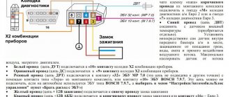
Cleaning and adjusting Valtek 37 LPG injectors — logbook of the 2010 Chevrolet Lacetti SW on DRIVE2
I cleaned the injectors a couple of weeks ago, and now I’m just about to write about it. The cold weather came and the car began to stall in the mornings when switching from gasoline to gas, after 2-3 stalls it switched to gas, stalled for about 5-10 seconds and then It was already working fine. Suspicion immediately fell on the gas injectors. Apparently deposits had accumulated, which froze at night and the rod stopped moving normally; after the injectors warmed up, the rod began to move normally and everything became fine. Gas consumption has also noticeably increased, I don’t know because of the injectors or simply because of the cold and long warm-ups, but the consumption has become prohibitively high - about 18-20 liters in the city.1. We close the valve on the gas cylinder and produce gas from the main line.2. Remove the rail with injectors.
Gas rail with injectors
3. Unscrew the screws and take out the injectors.
4. We take out the rods. They show deposits.
5. Wipe the rods and inside the injectors, naturally with alcohol