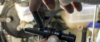
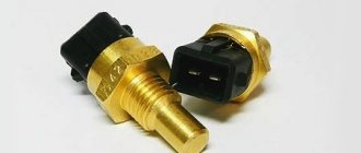
Description of the brake pedal sensor
Below we will find out how it works and how to replace it.
Purpose, location and operating principle
The essence of the system is that when you press on the brake, the piston in the cylinder begins to move. After this manipulation, fluid enters the brake system from the intake valve. It passes through the pipelines towards the main wheel mechanism, thus creating a suitable situation for the pads to move towards the wheel discs and drums. As a result, contact and subsequent braking occur. The controller itself turns on the brake lights.
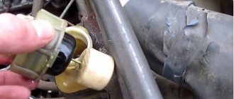
Brake end piece
Typical malfunctions and methods for their elimination
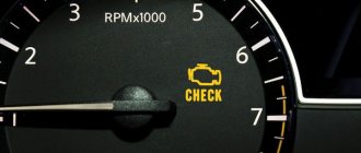
When “communicating” with a car, you can encounter various problems, but there is the most common and annoying problem. This problem is called error P0504, or otherwise “Brake pedal sensor mismatch.”
This malfunction often slows down the car. To solve this issue, you need to release the brake pedal and adjust the gap in the position sensor.
The adjustment is quite simple:
- It is necessary to hang a small but weighty weight in the area of the rubber brake pad.
- Unscrew the sensor nut a little and bring the white part to the brake pedal so that there is a gap of 0.2-0.5 mm between the body thread and the white tip. The sensor must be fixed in this position.
New replacement part
Detailed electrical diagrams of car components
Instrument panel wiring harness wiring diagram
1,2,3,4 blocks of the instrument panel wiring harness to the rear wiring harness blocks; 5,6 blocks of the instrument panel wiring harness to the blocks of the front wiring harness; 7 block of the instrument panel wiring harness to the block of the wiring harness of the air supply box; 8 block of the instrument panel wiring harness to the block of the front wiring harness; 9 lighting control module; 10 ignition switch; 11 on-board computer mode switch; 12 windshield wiper switch; 13 horn switch; 14 light signaling switch; 15 instrument cluster; 16 evaporator temperature sensor; 17 interior air temperature sensor; 18 air conditioner switch; 19 controller of the automatic climate control system; 20 heater damper gearmotor; 21 rear window heating switches; 22 alarm switch; 23 brake signal switch; 24 cigarette lighter; 25 electric power steering control unit; 26,27 connectors for the instrument panel wiring harness to the radio; 28 backlight lamp for the heater control panel; 29 lighting Lada Kalina; 30 mounting block: K3 additional starter relay; K4 additional relay; K5 relay breaker for direction indicators and hazard warning lights; K6 wiper relay; K7 relay for high beam headlights; K8 horn relay; K9 relay for turning on fog lights; K10 relay for turning on the heated rear window; K11 electric seat heating relay; K12 air conditioning compressor clutch activation relay; 31 heater motor switch; 32 electric heater motor; 33 additional resistance of the heater electric motor; 34 glove box lighting; 35 glove box lighting switch; 36 control unit of the automobile anti-theft system APS6; 37 driver airbag module; 38 passenger airbag module; 39,40 the instrument panel wiring harness blocks to the ignition system wiring harness blocks.
Electrical connection diagram for the wiring harness of the ignition system Lada Kalina 11174, 11184, 11194
1 oil pressure warning light sensor; 2 coolant temperature indicator sensor; 3 additional fuse box; 4 fuses for the electric fan of the engine cooling system; 5 electric fuel pump relays; 6 relays for the electric fan of the engine cooling system; 7 ignition relay; 8 relays 2 of the electric fan of the engine cooling system; 9 relay 3 of the electric fan of the engine cooling system; 10 electric fan of the engine cooling system; 11 throttle position sensor; 12 idle speed controller; 13 coolant temperature sensor; 14 diagnostic block; 15 ignition system harness block to the instrument panel harness block; 16 solenoid valve for purge the adsorber; 17 speed sensor; 18 ignition system harness block to instrument panel harness block 2; 19 mass air flow sensor; 20 crankshaft position sensor; 21 oxygen sensors; 22 controller; 23 rough road sensor; 24 diagnostic oxygen sensor; 25 ignition coil harness block to the ignition system harness block; 26 ignition coils; 27 ignition system harness block to ignition coil harness block; 28 spark plugs; 29 nozzles; 30 resistor; 31 air conditioning pressure sensors; 32 blocks of the ignition system harness and injector wiring harness; 33 phase sensor; 34 knock sensor.
Instructions for replacing the brake controller
- Pump out the liquid.
- Place the vehicle on a support stand and remove the wheel.
- Use a wrench to unscrew the two wheel pins.
- Remove the brake drum.
- Then, using a screwdriver, pull out the hook of the upper tension spring and remove the part. Perform the same manipulation with the lower tension spring.
- Then remove the front pad and spacer bar, while disconnecting the pressure spring and lower the pad.
- Remove the shoe lever from the parking brake hole, straighten the cotter pin and remove it from the parking brake drive.
- Remove the washer and lever.
- Install a new block and assemble the part in the reverse order.
Rear disc brakes on Lada Kalina
What to do if the brake fluid indicator on a LADA is on
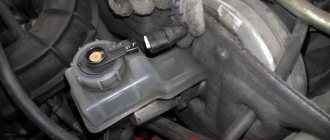
The brake system emergency indicator should light up red when the ignition is turned on and go out 2 seconds after the engine starts. Long-term lighting of the lamp while the engine is running indicates that the parking brake (handbrake) is engaged or the brake fluid level has dropped below the “MIN” mark. It is prohibited to operate a vehicle with the indicator on!
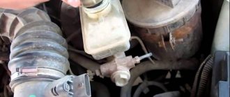
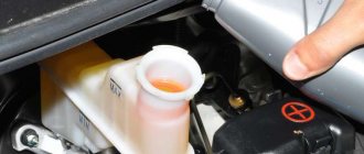
The brake fluid level sensor is located in the master cylinder reservoir. When the liquid level drops below o, a signal from the sensor lights up a warning lamp on the instrument panel. It is recommended to check the brake fluid level sensor at each scheduled maintenance inspection.
Description of the clutch pedal sensor
What kind of device is this and how to replace it is below.
Purpose, location and operating principle
The clutch sensor is installed directly on the clutch pedal. It influences engine control with an electronic gas pedal and provides a convenient and flexible control scheme for machine modes. On its own, it looks like a nondescript switch that has on and off modes.
Typical malfunctions and methods for their elimination
If the controller does not detect signals from the clutch, then there is a risk of error 0830. The occurrence of this problem is usually a malfunction of the clutch sensor or a short circuit or open circuit. To correct this state of affairs, it is necessary to identify the reasons. That is, inspect the contacts for breaks or corrosion.
Priora brake fluid level sensor
Hello. Such a problem. Today I noticed that the brake fluid indicator began to blink (exclamation mark in a circle). The brake fluid is filled to capacity. I filled it up when I changed the front brake pads a month ago.
The rear pads sometimes locked a couple of times when moving backwards. Not now. I noticed that the indicator blinks mainly when you pass a speed bump, and sometimes like that. What could it be? Rear pads?
- Stutters when starting off in reverse gear of the Priora - 3 answers
- Front pads whistle on Lada Priora - 2 answers
- Tapping from the right rear in Lada Priora - 2 answers
- How to replace brake pads on a Priora 2170? – 2 answers
Badge number 21? If so, then the problem may be, for example, in the brake fluid level sensor, try disconnecting the connector and driving it.
Most often, this problem occurs in the brake fluid reservoir. For example, the float gets stuck and cannot float up. Or it cannot float up because it has become saturated with liquid through the resulting leak (crack, hole) and has become heavy.
You open the lid, lift it along with the float and check how it moves freely up and down, and whether it is filled with liquid (it should be empty when it is working).
Just in case, a question: did you check the level today or then, a month ago, when you changed the pads?
Installed on VAZ cars of the tenth family (VAZ 2110, 2111, 2112).
Pay for goods by credit card, using QIWI, Yandex.Money or WebMoney and save on your purchase from 4%, avoiding postal and bank commissions
This product was chosen by 3 customers
Specifications:
- The sensor provides opening and closing of a DC electrical circuit of no more than 1 A with a rated voltage of 12 V and no more than 0.5 A with a rated voltage of 24 V, as well as when the voltage changes from 90 to 125% of the rated value.
- The sensor ensures that the electrical circuit is closed when mechanical pressure is applied to the central part of the protective cap by forcefully acting on the sensor contacts.
- The degree of protection of the sensor installed in the tank from the penetration of foreign bodies and water is IP55 according to GOST 14254.
- The sensor contacts close when there is a loss of brake fluid, determined by the size of 40.5-42.5 mm from the upper edge of the reservoir neck to the surface of the brake fluid and does not have “false” alarms when braking the car and when driving on a rough road.
- The transient resistance of the sensors is no more than 65 MOhm in normal climatic conditions.
Terms of Use:
- operating temperature range - from -45°C to +85°C;
- relative humidity up to 98% at a temperature of 40°C.
Weight, kg: 0.1 Dimensions, cm: 8 x 7 x 4 Volume, m3: 0.00022
Sensors on the brake pedal - what do they affect?
In general, I once again connected the computer to the car - I climbed in the “01 engine” section
I found this indicator there - I don’t remember exactly what it’s called - something about brake sensors in the three-zero field - when I press the brake pedal I get this picture: 000 pedal released 010 first 5-10 mm 011 after another 10 mm
The first zero never changes to one. I think I read somewhere that if the brake pedal sensors are not synchronized, then . in general, everything is bad - the car starts working not according to the fact, but according to a pattern, the first “0” is what kind of sensor is it - where is it, how does it change?
Phaeton
Registration 09/03/2007 Address Russia, Moscow, South-Western Administrative District Age 87 Messages 4,901
| Thank you: |
| Received: 116 Sent: 51 |
There is one sensor, for all zeros. Search for “Frog”, there is a detailed description of the replacement. But why change it if you don’t have any errors? My reason for replacement was burnt contacts and, as a result, a sporadic error in the stop sensor.
Added after 10 minutes 33 seconds:
It’s strange, contacts are transferred, but ones are only added? Of course, you may have a sensor from a different system.
Polo
Registration 11/27/2007 Address Russia, Yaroslavl Age 41 Messages 428 Diary entries 1
| Thank you: |
| Received: 0 Sent: 1 |
here is group 006 second field Brake pedal F/F47/F36
I read somewhere about “all trade wind sensors”; it described all the sensors that are on the car and what they affect; I definitely didn’t dream about it; for example, there was a paragraph about the crankshaft sensor and a description of what would happen if.
The brake pedal sensors were described in a similar way - there are three of them, one is a frog - turns on the light and two more - these two should work synchronously - if not, then the computer switched something to emergency mode and worked according to the factory template, and not in fact.
Phaeton
Registration 09/03/2007 Address Russia, Moscow, South-Western Administrative District Age 87 Messages 4,901
| Thank you: |
| Received: 116 Sent: 51 |
Everything is correct, but this is about the accelerator pedal sensor. [-X
How to check the Priora brake fluid sensor
- To the beginning of the forum
- Forum Rules
- Old design
- FAQ
- Search
- Users
Tell me how to check the functionality of the emergency brake fluid level sensor? There are suspicions that it does not work. If you close the connector contacts, the light on the device will light up, or this cannot be done. Is it the same on number 10 as on number 9 or something else?
The lamp on the panel works, i.e. lights up when the starter is running.
on the rubber plug of the brake fluid reservoir plug
Somehow today the topics on the forum are one better than the other: one has a problem due to the gasket between the steering wheel and the seat https://www.autolada.ru/viewtopic.php?t=94122&postdays=0&postorder=asc&start=0 the other has hemorrhoids from that what he thinks is how to check whether the light turns on if the float is sinking (no offense, but today something like this makes me sick), the third was washing the car in some ditch, somewhere in the village of Kazyulino and GIBBon on focus became attached to him https ://www.autolada.ru/viewtopic.php?t=96208 and he doesn’t have any documents with him. Maybe some storm in the sun or an aggravation in the spring.
Causes of sensor malfunction and their symptoms
In most cases, the above error occurs because the sensor has not been adjusted properly. It is for this reason that the car owner notes the emergence of such problems as:
- instability of the engine: it starts poorly or stalls immediately;
- instability of speed.
The sensor combines two functions: it is both an element of the brake pedal position and a brake light switch. Most often, the malfunction is caused by the sensor misalignment already mentioned above, or by a broken spring. The problem that has arisen manifests itself by the “check” icon lighting up and error P0504 (implying a mismatch in the operation of this part).
How does the GTZ function?
The unit consists of the following parts:
- metal housing with holes for supplying brake fluid, pedal rod and connecting the expansion tank;
- 2 pistons with rubber seals;
- 2 return springs;
- guide bushings;
- end plug with gasket.
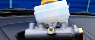
An expansion tank is attached to the top of the main distributor body, where excess fluid goes through compensation holes. Inside, the element is divided into 2 cylinders with separate pistons standing on the same axis.
The blind end of the housing is closed with a threaded plug; on the other side there is a flange for attaching to the vacuum booster. The brake pedal rod is attached to the first piston. The brake circuit pipes are connected to the lower holes - separately for the front and rear wheels.
The operating principle of the master brake cylinder looks like this:
- When you press the pedal, both pistons simultaneously move forward and push fluid into the circuit tubes. Under its pressure, the wheel cylinders are activated, compressing the pads on the discs.
- Part of the liquid that does not have time to pass into the tubes flows into the expansion tank through special bypass holes.
- When the driver releases the pedal, the springs push the pistons back, returning them to their original position. Liquid from the tubes and reservoir refills the cylinders.
- To compensate for the expansion of the liquid (for example, from heating), another pair of holes is provided leading to the expansion tank.
Carrying out pre-installation diagnostics
Before purchasing and installing a new sensor to replace a broken one, it is recommended to diagnose the old sensor and, if there is a breakdown, fix it yourself. There are two nuts on the sensor body, the first of which is located at the bottom, and the second at the top. The nut located at the top should adjust the clearance of the part (sometimes it is set incorrectly). This leads to disruption of the normal functioning of the button, therefore, you will need to set the gap so that there are no obstacles to its normal movement.
After the adjustment, the ECU error is reset, then you need to start the engine and wait about fifteen minutes, since errors are not recorded immediately. If error P0504 is not marked, it means that the cause of the engine malfunction was an incorrect sensor setting. If it appears again, you will need to replace this element with a new one.
Examination
2. Turn on the ignition.
3. By pressing from above, we recess the sensor float rod. In this case, the warning lamp for insufficient brake fluid level should light up on the instrument panel.
Recommendation: If the warning lamp does not light up, then the terminals in the block itself may have oxidized, the sensor is faulty, or the warning lamp for insufficient brake fluid level is faulty. To make sure that the test lamp is working properly, just short-circuit the terminals of the connecting block. The indicator lamp should light up. A faulty warning lamp must be replaced (see “Instrument panel - replacing lamps”). If the control lamp lights up when the terminals of the block are shorted, then the sensor is faulty and must be replaced.
Carrying out work on dismantling and repairing the sensor
In most cases, repairing a sensor does not take a significant amount of time and does not require the car owner to have either specific knowledge or the use of complex tools. You can do it yourself without going to a repair shop.
First you need to disconnect the negative terminal from the battery, and then move to the driver’s seat in the car. Move the front seats back as far as possible and remove the interior carpet. The sensor is located next to the brake pedal; to remove it, you will need to disconnect the clamp and the block with wires from its connector.
Carefully loosen the fastening nut and carefully unscrew the body of the part, then disassemble it. This element is a two-piece element, and both parts are held in place with latches.
There is a spring in the inside of the sensor, which is often what causes problems. Replacing a faulty spring with a new one, having the same number of turns and suitable dimensions, most often helps to eliminate the problem.
Having completed the repair, reassemble the element by performing the manipulations you performed to disassemble it in the opposite sequence, and then install it in its original place, and if necessary, adjust it. The part is tightened until the brake pedal goes down, after which it is turned 90 degrees clockwise and secured with a lock nut. As a result, with the brake pedal lowered, the switch rod will be in a recessed position, and when you press it, it will go beyond the boundaries of the switch body.
Next, start the engine and wait at least ten minutes; if the error does not appear, you have correctly identified the cause of the problem. If error P0504 appears again, adjust the sensor; if this error continues to appear, the part will need to be replaced.
Repair of the brake fluid sensor float in Lada Priora
The brake fluid sensor float malfunctioned for 3 weeks at -5 -20. Came to visit. The brake fluid check started popping up just like the regulations: It's on, it's squealing.
Everything is according to the instructions, as seen in the 2011 owner's manual.
1. Checked the fluid in the reservoir. It's a little more than half. Topping it up didn't help. On the road, it appears and disappears. 2. I decided to remove it and figure it out, here’s what happened: — Unscrew the fixed lid, carefully pull it out, wait a couple of seconds for the liquid to drain. Shocked, tugged. It feels like it’s coked, the movement is very tight. The rubber bands crawled one on top of the other, it is not clear how. The bottom float itself stuck stupidly to the rod. He drove like this for a couple of days, he completely stopped showing signs of life and stopped blinking. Let's look further.
3. The sensor, disassembled into parts, works just fine with the rod, moves back and forth on
4 mm as expected. Having connected it in disassembled form, everything is fine! Let's take a look further. By pressing one side, we squeeze it out of the lid (not necessary at all), I couldn’t insert it back myself, but a friend did it in 5 seconds.
4. The rod itself had a good chat back and forth. I folded back the extra inner elastic as shown in the picture (I ended up throwing it out a little later). Pulling the float down, I took it apart into small pieces; the structure couldn’t be easier to disassemble. Again I developed a plug (rod). Put it back together. Now I notice the difference. I checked the operation of the float rod under my own weight, everything works like a clock,
The 4mm stroke is maintained, checking the power supply - it works under its own weight. Then everything was carefully placed and screwed. I checked it a day later and it seems to be working.
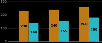
5. Conclusion. 20 minutes of work. Fifth grader design. (Price new
230 rubles), mine seems to work. Be sure to monitor the level of brake fluid in the reservoir yourself and there will be no troubles.