VAZ tachometer connection diagram
The first car from the Zhiguli family equipped with a tachometer was the VAZ 2103. Neither 2101 nor 2102 had such a device. The tachometer is used to measure the crankshaft speed. It is a revolution counter, showing their number by deflecting the scale needle to a certain angle. The tachometer is also indispensable when setting up the carburetor - its indicators are taken into account when adjusting the idle speed and the quality of the fuel mixture.
Repair (resurrection) BSK
Over the entire 4 years of using the car, the display unit (BI) turned on at most 10 times, and then everything was limited to the beeping and blinking of the lights at the moment when I took out the ignition key. Then I somehow noticed that if I moved the key in the lock, the BI would also blink. I started by studying this topic on the Internet.
I found two reasons for this problem: - poor contact on the BI connector, - worn out ignition switch. I think it’s unlikely that anyone will change the lock just to see errors on the BI; on the contrary, some people specifically disable it. But it would be convenient for me to see if there is fluid in the washer reservoir without opening the hood.
I climbed to look at the wires on the BI, it turned out to be original, manufactured on 06.2001. It is easier to remove it with the watch removed; you need to pull it hard. Indeed, the block with the wires was inserted crookedly. I corrected it and... lo and behold, it works. After a couple of days, I realized that the BI still turns on every other time, I have to turn the ignition on and off several times.
Of course, I wasn’t going to change the lock and suddenly I came across the same problem on one of the VAZ forums and it was solved with a guaranteed and simple solution. You just need to solder a diode between two wires No. 1 and No. 5 in the BI. Any diode is suitable, I had several from an old computer power supply, of course IN5406, which can withstand up to 600V would be superfluous here, but it just fit the length of the legs, so I installed it, a new diode with uncut legs will naturally also reach.
VAZ-2106 tachometer connection diagram
The “Sixes” were equipped with a tachometer model TX-193. This tachometer consists of:
- plastic cylindrical body with glass holder;
- a scale divided into zones of safe and dangerous modes;
- backlight lamps;
- a milliammeter with an arrow attached to its shaft;
- electronic printed circuit board.
The principle of its operation is based on measuring the number of electric current pulses in the primary (low-voltage) circuit of the car’s ignition system. In the VAZ 2106 engine, for one revolution of the distributor shaft, corresponding to two rotations of the crankshaft, the contacts in the breaker close and open exactly four times. These pulses are removed by the device from the final terminal of the primary winding of the ignition coil. Passing through the parts of the electronic board, their shape is converted from sinusoidal to rectangular, having a constant amplitude. From the board, the current flows to the winding of the milliammeter, where, depending on the pulse repetition rate, it increases or decreases. The arrow of the device reacts precisely to these changes. The greater the current, the more the arrow deviates to the right and vice versa.
Connecting a tachometer in carburetor VAZ 2106
Electric circuit of the speed counter of the carburetor “six”
In a contactless ignition system, the tachometer is connected not to the coil, but to the switch
Connecting a tachometer in injection VAZs
It should be taken into account that the colors of the wires and their purpose may differ depending on the manufacturer of the device, but for the standard “TX-193” device, which is usually used in “sixes”, the diagram is as follows:
- A white cable is required to connect the backlight.
- The red wire is connected to the ignition switch, a fuse is used for this, this cable supplies power when the ignition is activated.
- A white cable with a black break is required for connection to the car body.
- The brown wire connects to the K+ terminal on the coil.
- The black wire is connected to the charging current indicator relay. The latter, in turn, is installed on the right in the engine compartment.
- The gray-black cable is required to connect to the engine fluid pressure regulator installed to the left of the engine.
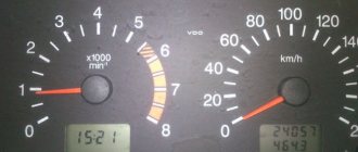
Designation of icons on the dashboard of Lada 2112
For a better understanding of the purpose of the indicators, their interpretation is given.
| Number in photo | Interpretation of lamps and indicators |
| 1 | Coolant temperature indicator; if the light comes on at the top of the scale, the engine has overheated. |
| 3/4 | The turn signal indicators light up simultaneously when the hazard lights are turned on. |
| 7 | Empty tank indicator; if the lamp lights up, stop at a gas station. |
| 8 | External lighting is turned on and operating normally. |
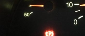
| 9 | The pressure in the brake system has dropped. It is necessary to immediately add fluid to the expansion tank of the system. |
| 10 | The high beam headlights are activated. |
| 12 | The odometer display shows non-resettable mileage. |
| 13 | The hazard warning lights are on. |
| 14 | The engine control system is damaged or not working correctly. |
| 15 | The battery is not receiving a charge. In this case, you should check the battery itself for wear and the generator set. |
| 16 | The handbrake is activated. |
| 17 | The oil pressure in the engine crankcase has dropped below normal. You should add fluid to the specified level and check the operation of the pump. |
| 18 | In a configuration with an airbag, it indicates that the squib drive is turned off. In other versions the light bulb is a backup one. |
Connection diagram for tachometer VAZ-2108 and 2109
Let us immediately note that the fuel supply system – injector or carburetor – does not play a special role here. As you know, currently the most common are cars with the following engine types: gasoline or diesel. Depending on this, the tachometer is selected, unless, of course, it comes in the stock version. The thing is that on gasoline engines the tachometer reads data from the ignition coil, or rather, the impulses that arise here. However, the design of diesel power plants does not provide for this unit. Accordingly, here the tachometer reads pulses not from the ignition coil (for lack of one), but from the generator.
The first two wires (12-volt and Signal) are to contacts “B” and “K” of the ignition coil, respectively. All that remains is to secure the mass in any convenient place.
The problem may be caused by a ground wire
Sometimes situations arise when the needles on instruments behave completely inappropriately, jumping sharply from the minimum to the maximum mark and vice versa. In the vast majority of cases, the cause of this malfunction is the lack of normal contact with ground. There is nothing difficult in fixing this problem. First of all, you should find the fastening of the ground wire connecting the instrument panel to the partition that separates the interior from the engine compartment. It can be detected by removing the car radio from its standard socket.
However, there is one caveat here. If an alarm was installed on the car, then the fastening of the mass wire could well be moved to some other place. However, as a rule, the car owner is warned about such actions. In most cases, the fastening of the mass wire is moved to the area where the driver’s left foot is located, placing it behind the interior trim.
By the way, a situation where the arrows on the instruments begin to “jump” can also arise after installing the radio. In order to do this, you need to unscrew the ground wire coming from the dashboard. It happens that it is then screwed in poorly, and subsequently, due to body vibration, the contact becomes unreliable. To solve the problem, just twist the wire normally. It is worth noting that doing this is not very convenient, so you will have to make some effort.
VAZ-2110 tachometer connection diagram
- tachometer VAZ;
- trip computer;
- ECM;
- crankshaft position sensor;
- ignition module.
Tachometer VAZ 2110 - with four outputs: if it is on a car with injection, it is connected not to the ignition (input 2), but to the ECM controller with an additional output provided for this (input 1) - and in this case it reads the number of revolution pulses directly from the controller. It receives a signal about the position of the shaft.
What exactly needs to be done
Check the cap on each of the wires: if the copper is burnt, clean it with ASIDOL, ammonia and ordinary chalk. The taps on the module should also be cleaned. For better protection, you can apply lithium grease (Litol-24). Here's what you can't do:
- Check for the presence of a spark by bringing a “grounded conductor” to the tap;
- Connect the “+” terminal removed from the battery to ground with the engine running;
- Apply voltage “+12” to any of the module contacts.
How to perform an express check: the key is at “0”, then we measure the resistance between taps 2-3, 1-4. Both values must match. By the way, the multimeter must be a dial gauge.
About the DPKV tachometer sensor
The tachometer has a sensor (crankshaft position sensor - DPKV). This device serves not only to count crankshaft revolutions, but also to determine its position at a certain moment, which is necessary for the electronic control unit to ensure proper operation of the power unit. When a metal object passes near the sensor core, an electrical impulse is generated in it, which is transmitted to the electronic engine control unit. The role of such an object in the power unit of a car is played by the crankshaft gear.
Symptoms
Any malfunction is preceded by the appearance of symptoms, minor problems or breakdowns. The tachometer was not spared similar signs. Symptoms of a tachometer malfunction are as follows:
- Poor operation of the instrument needle. It stops responding to an increase in speed, trembles, slowly decreases with a sharp decrease in speed, and gets stuck in a certain position.
- The dashboard stops working completely. The speedometer does not respond to changes in speed modes, the backlight does not turn on.
- The power unit loses power, speed stability, and stalls when shifting into gear or accelerating.
- High fuel consumption. The ECU cannot calculate the number of revolutions correctly. A speed sensor is involved in this calculation; failure of the tachometer system introduces a data error between all devices.
All the described symptoms appear as a result of the fact that the tachometer system for counting the revolutions of the power unit stops working smoothly. The following will describe how to check each element of the tachometer.
Why does the VAZ tachometer jump?
It often happens that the needle starts to twitch. If the car is fuel-injected, then troubleshooting involves connecting a diagnostic scanner and checking the engine systems. Jumps in the TX-193 needle in most cases are also a symptom of malfunctions associated with its electrical circuit. The reasons for this behavior of the device may be:
- lack of good contact at the negative terminal of the battery;
- oxidation or burning of the brown wire on the ignition coil;
- burning or wear of the contacts of the ignition distributor cap or slider;
- wear of the distributor shaft bearing;
- shorting the red wire powering the device to vehicle ground;
- malfunction of the crankshaft position sensor (for injection engines).
A similar problem is solved by stripping the contacts, replacing the ignition distributor cap, slider, support bearing, restoring the integrity of the insulation of the device’s supply wire, and replacing the crankshaft sensor.
Another jump may be due to the inoperability of the capacitor located at the bottom of the breaker. The capacitor may be broken or its contact is very weak.
Removing the old and installing a new panel
The process of replacing a Europanel does not require inviting highly qualified craftsmen.
Accompanied by preliminary preparation:
- battery power is turned off;
- The steering wheel and the facing part of the column are removed;
- sometimes the seats come out.
Removing the old panel
Dismantling instructions:
- The shields located at the feet of people sitting in front are dismantled.
- The curved plug is removed from under the handbrake;
- The window regulator cover is removed and the cigarette lighter connector is removed.
- The cover is removed from the gearbox lever. The air ducts going to the rear seats are removed.
- The plastic covers of the roof pillars are removed. The radio is pulled out.
- The plugs are removed from the top of the panel. The nuts that appear are unscrewed.
- Then the bolts located along the contour of the lower edge, as well as at the feet of the driver and passenger, are unscrewed;
- The mounting block is dismantled and the plastic casing is removed.
Installation of a new panel sample
Both panels have different dimensions, therefore, installation is carried out using 3 methods:
- a new instrument cluster is adjusted to the existing panel dimensions;
- the panel is being completely replaced with a new sample;
- Installation of the Euro-plate is underway.
The latter method is rarely used. This is due to the fact that installation requires combining the wiring. Work is being carried out on a panel removed from the car.
If the panel on a VAZ 2110 does not work, you need to check the condition of each indicator. Make sure the safety elements are reliable. Next move on to checking the sensors. If a breakdown is detected, repair it. If the unit cannot be repaired, replace it.
If the tachometer on a VAZ does not work
Usually, the lack of response from the arrow is due to a broken contact in the connectors of the main wires of its connection, or damage to the wiring of the circuit. The first step is:
- Inspect the fastening of the conductor in brown insulation to terminal “K” on the ignition coil. If you detect poor contact, traces of oxidation, burning of a wire or terminal, fix the problem by cleaning the problem areas, treating them with anti-corrosion liquid, and tightening the fastening nut.
- Check the reliability of the connection of the black and white wire to the vehicle ground. If contact is broken, clean the wire and the surface to which it is attached.
- Using a tester, determine whether voltage is supplied to the red wire when the ignition is on. If there is no voltage, check the serviceability of fuse F-9, which is responsible for the integrity of the instrument panel circuit, as well as the condition of the ignition switch contacts.
- Disassemble the instrument panel and check the connections of the contacts in the tachometer wiring harness block. “Ring” all the wires going to the device with a tester.
Examination
It is better to test the component components of the engine speed counting system in order of priority. This will help to quickly identify the malfunction and conduct an additional examination of the condition of each element.
Before checking the electrical circuit and its parts, you should make sure that the fuel injection system is working. The serviceability of the gas distribution mechanism also affects the performance of the tachometer. Only after checking these components can we assume that the tachometer circuit is not working.
DPKV
This device is located near the machine's generator pulley. You can check its operation using a multimeter. To do this you need:
- Set the multimeter to resistance measurement mode.
- Disconnect the sensor power supply connector.
- Connect the red control probe of the tester to terminal “1”.
- Connect the black measuring probe to terminal “2”.
- Crank the engine with the starter.
When open, the device will show a resistance of up to 550–750 Ohms. If the tester does not measure the operating resistance of the sensor, you will have to dismantle it. To do this, you will need to unscrew one nut that secures the element. Very often, metal shavings stick to the magnetic sensor and interfere with the opening. If chips have accumulated on the rod, they must be removed, the body must be cleaned with a solvent and the resistance measurement must be repeated.
After checking the DPKV, you need to check the integrity of the wiring that powers the sensor and transmits pulse signals to the control unit. It is necessary to inspect the wires and check the integrity of the insulation. You will also have to clean both halves of the connecting plug with solvent.
Ignition module
This device is most often prone to breakdowns. This happens due to a short circuit to ground. The check is carried out with the engine running. During operation of the power unit, it is necessary to remove the power wires from the spark plugs one by one. After this, you need to direct the end of each wire towards the engine block, but without touching it. A spark should appear from the end of each wire. It should be blue. If the spark is yellow or there is no spark at all, the module and wires will have to be ringed.
The wires can be tested with a multimeter only to check the integrity of the cores. It is not possible to determine an insulation breakdown in this way. It is better to replace all suspicious elements with new ones. Often, owners replace standard high-voltage wires with modern silicone analogues; this should not be done. The electrical resistance of such wires is very high; it does not allow the spark of the required discharge to pass through. It is also worth carefully inspecting the caps that are placed on the candles. Parts with poor contact or external defects must be replaced.
Before checking the module, you need to test the wiring that powers this device. To do this, you need to disconnect the plug. Next, you will need a multimeter in DC voltage measurement mode.
- Connect the red measuring probe to terminal “1”.
- Connect the black measuring probe to terminal “3”.
- Turn on the ignition.
The tester should show a voltage of 12 volts or equal to the battery voltage. If there is no voltage at all, then you need to check the integrity of the fuse responsible for the ignition module. It is located under the trim on the right side under the instrument panel, the very first one on the hood side. Has a rating of 15 amps.
If voltage is supplied to the module, then it is necessary to check each coil of this assembly.
- The primary windings are checked for the presence of operating resistance. To do this, you need to switch the multimeter to resistance measurement mode. Next, you need to connect the red test lead to pin 1 of the power wire going to the first cylinder, and the black test lead to pin 4 of the cylinder. The operating resistance must be at least 0.5 Ohm.
- The second primary winding is checked in the same way, only at terminals 2 and 3.
Next, the secondary winding is checked. To do this you need:
- Connect the red measuring probe to terminal “1” on the module socket.
- Connect the black measuring probe to terminal “3”.
- The operating resistance should be 0.5 Ohm.
The third check is the most important. It is carried out to test for the presence of a short circuit.
- The red test probe is connected to the module's connecting socket.
- The black test probe is connected to the device body.
- A working module should not show resistance. If it is, even the most minimal, then the device will have to be replaced.
If the module has fully passed the test, it must be inspected. Any cracks in the housing, even the most minor ones, can create a ground fault during operation in wet weather. Such deformations cannot be eliminated; the unit will have to be replaced with a similar one. You also need to clean the sockets of the high-voltage wires going to the spark plugs.
Fuse
Very often the tachometer does not work due to a fuse problem. If the instrument panel does not work at all and there is no backlight, then we can assume that fuse “F9” has failed. It must be removed and checked using a tester. The multimeter is switched to continuity mode, both test leads are connected to the fuse contacts. The absence of a buzzer will indicate a malfunction of the protective element. It will have to be replaced with a similar device rated 10 amps.
You also need to check the fuse socket. Clean any dirt, oxidation, carbon deposits with alcohol. Bend the contacts with a screwdriver.
Next, the electrical voltage coming to the fuse is checked. This requires:
- Switch the multimeter to voltmeter mode to measure DC voltage.
- Connect the red test lead to the fuse output.
- Connect the black test lead to ground.
- Turn on the ignition.
The voltmeter should show a voltage identical to the battery charge.
Receiver block
If the previously described checks did not bring results, and all the elements are in good order, then you need to test the tachometer itself. A simple check is to reset the odometer. After resetting, you need to hold down the odometer button and turn on the ignition. The tachometer and speedometer needles should deviate to the maximum position and return back. If the tachometer does not respond to the voltage supply, you will have to dismantle the dashboard and remove the device. To do this, you need to unscrew the 4 screws of the cladding in front of the protective glass and dismantle it. Next, remove 4 more screws holding the instrument panel itself. After dismantling, you need to pull the block towards you.
Electrical power is supplied to the tachometer through a yellow (sometimes white) connector. “+” terminal number “8” is the very first in the bottom row. To check the power supply, you must:
- Switch the tester to DC voltage measurement mode.
- Disconnect the plug.
- Connect the red probe to pin “8” of the incoming power cable.
- Connect the black probe to ground.
With the ignition on, the voltmeter should show a voltage of up to 12 volts. If there are no readings, then you should check the ignition switch terminal.
Next, terminal “2” of the receiver unit itself is checked. She is the very first one in the top row. Responsible for power supply with pulsed current. To check it, you need to run a test wire from the “+” terminal of the battery. The second end of the wire must be abruptly connected to terminal “2” several times. The tachometer needle should respond to the simulated impulses by deflecting at a certain angle. If there is no deviation, then the reason lies in the receiver itself.
It needs to be inspected visually for oxidation and broken tracks. A big problem with such receivers is microcracks in the solder. You should carefully inspect all connections and eliminate any defects found. Then repeat the check again.
If the receiver unit is working properly, power is supplied from the ignition and there is a reaction from the arrow to simulated pulses, then the problem lies in the ground terminal. It is the very first one, located in the corner between the rows of plugs. Necessary:
- Set the tester to voltmeter mode.
- Connect the red test probe to terminal “2” of the incoming cable plug.
- Connect the black probe to terminal “1” of the same plug.
- Turn on the ignition.
If there are no readings, then it is worth connecting the black control probe to ground in another place. The presence of data will indicate a break in the ground line. It can be pulled through using a jumper and pre-fixed with a bolted connection in the engine compartment.
Pioneer DEH-1500UB
pionrrr mvh-150ub gives an amplifier error amp error
Answers 1
Try turning off all the speakers, amplifiers, etc., leaving only the power and try turning it on, if it works, then connect one speaker at a time and look for where the short is.
Watch another video:
Sound amplifiers are needed in order to improve the quality of music playback by reducing its distortion when turning on high volumes. Sometimes car owners encounter amplifier errors on the Pioneer radio: the sound disappears in the speakers, and then the equipment starts working again, while the display shows “ERROR” DC." There are several ways to troubleshoot problems; you can choose the right one by determining the cause of the problem.
Classification by operating principle
- Mechanical or electromechanical tachometers with direct drive. The revolutions are transmitted to the dial indicator through a flexible shaft, which, through a worm gear, receives rotation directly from the crankshaft or one of the transmission shafts. The operating principle of the indicator is based on the phenomenon of eddy current induction. The operation and design of a magnetic tachometer are extremely similar to the operating principle of a car speedometer. In modern cars, a similar tachometer design is not used.
- Electric machine. A distinctive feature is the connection to a generator. It is used primarily on diesel engines, but for the purpose of unification, a device of this type can also be used on gasoline engines.
- Electronic. The signal can be taken either from the ignition system or directly from the computer. Installed on gasoline and diesel internal combustion engines.
Design and principle of operation
Main components of electric machine and electronic tachometers:
- measuring unit, or signal converter. It can be based on elements of analog circuitry or built using special microcircuits;
- display unit with analogue or digital display of the number of revolutions;
- auxiliary elements.
The operation of electronic tachometers is based on the conversion of individual signals or pulses captured from the computer, ignition system or generator into a signal “understandable” for the display unit.
Connection diagram
When looking for the reason why the tachometer does not work, it is first of all important to understand the connection diagram and the type of signal. There are 3 typical connection schemes:
- to a contactless ignition system (the tachometer wire is connected to the primary circuit of the ignition coil). The operating principle is based on measuring the frequency of voltage surges in the primary circuit of the ignition system. Calculating the ignition angle is impossible without focusing on the number of crankshaft revolutions, therefore the sparking frequency directly depends on the crankshaft rotation speed. On 4-cylinder internal combustion engines, a full revolution of the crankshaft corresponds to 2 voltage pulses in the primary circuit. Accordingly, the higher the crankshaft rotation speed, the greater the frequency of voltage surges;
- connection to the contact ignition system. The operating principle and connection diagram are similar to the BSZ, but the design of the measuring unit will differ depending on the voltage of the input circuit;
- connection to the engine ECU. The principle of operation is still based on recording voltage pulses in the primary circuit of the ignition system, but the signal to the tachometer comes from the engine control unit;
- connection to the generator (the tachometer signal contact is connected to terminal W of the generator). The rotation of the generator pulley is carried out by a belt drive from the crankshaft, so the rotation speed of the generator rotor will always be proportional to the crankshaft speed. The change in the number of revolutions of the crankshaft can be calculated by constantly measuring the amount of EMF generated on the winding. According to its principle of operation, an electric machine tachometer resembles a regular one class=”aligncenter” width=”448″ height=”412″[/img]
Typical faults
If the mechanical tachometer on a car stops working, there is mechanical damage to any of the structural elements. A broken cable of a flexible shaft, wear of the worm gear elements, the appearance of backlashes, deformations - all these reasons can cause the engine speed indicator to fail.
What to pay attention to if the electronic tachometer does not work:
- integrity of electrical wiring. In this case, it is important to check not only the signal wire, but also the ground and power supply of the instrument panel;
- quality of contacts. The presence of oxides and loose contact inside the chips may well cause the tachometer to fail;
- the integrity of the elements of the measuring unit, which are located behind the protective glass inside the dashboard. Among mechanical damage to transistors, burnout of microcircuits, tracks or swelling of resistors, the most common reason for a non-working tachometer is a violation of solder integrity. For example, on the Mitsubishi Padjero II, the appearance of microcracks in the soldering areas of the tachometer elements is a generally recognized disease.
General faults
During use, did you notice that the needle in the car’s speedometer is inactive (at any speed)?
The first thing you need to do is check the tightness of the fastening nut of the speedometer tips, as well as its drive.
speedometer tip nuts
If, after checking, no comments were found or the work performed did not bring the desired effect, in other words, there is a risk of damage to the speed indicator drive or breakage of the flexible shaft.
In the latter case, the part will have to be changed. In this case, do not forget to apply a good-quality lubricant to the area near the seal (Litol-24 may be suitable for these purposes).
Once the work is completed, push the shaft through the seal - this will help distribute the lubricant over the surface of the cable.
The occurrence of a knocking noise while driving may indicate a malfunction of the speedometer flexible shaft.
The reasons for this phenomenon include huge bends in the cable under the device panel, dents, etc. Make sure that the radii of the roundings do not exceed 10 cm.
From time to time while driving you can see a “growling” sound, approximately in the front part of the car. The reason may be the speedometer cable, which often makes noise in the absence of regular lubrication.
This is one of the more important car devices. Its task is to demonstrate the number of revolutions of the engine crankshaft at a certain point in time.
A tachometer breakdown is not that critical. But in the long term, it may become a prerequisite for engine malfunction and new costs for the car owner.
Speedometer not working properly
Because how can you cope with a breakdown, and what could be the main reasons for a breakdown?
In fact, there are not so few of them. In the case of an electric tachometer, in most cases the LED screen of the device fails. Repairing in this case is problematic - it is better to change the screen.
Nissan Qashqai tachometer contacts.
Nissan Qashqai tachometer contacts
Malfunctions of the tachometer are often caused by a decrease in the properties of the contacts or faulty wiring (in this case, impulses from the motor to the device may not arrive at all).
To eliminate such problems, you need to carefully examine all the wires for cracks and breaks. If you find a crack, simply solder it, and if a break is detected, replace part of the wiring.
The cause of a malfunction of the tachometer may be a failure of the engine speed sensor.
engine speed sensor
It is not difficult to diagnose the problem - the tachometer needle begins to “jump” in different directions. The only way to bring the tachometer back to “life” is by replacing this element.
speed sensor
Please note that the above malfunctions and methods for eliminating them are of a general nature. Each car model may have its own aspects, and we will talk about some of them in more detail.
Featured Posts
Anatoly-
Car VAZ21124 Y7.2 tachometer does not work. What I did was check all the electrical circuits connected to the tachometer, throw in a new electronic unit. I changed the instrument panel, the tachometer does not work. I tried and tossed the EB. Bosh7.9.7 worked, I return Ya7.2 does not work. The guy says that the tachometer worked before. Who has any thoughts, what is the ambush?
Xander ROTTEN DICK
Open the ECU and ring 8 pins... no other thoughts.
romelo
Did you do something with her, or did he already arrive like this? You need to ring with a control or an oscilloscope, starting from the block; if there is no signal from the block, then it is already clear that the block. If repair is unrealistic, then you can somehow hook it up to the injectors or coil.
Softer
Car VAZ21124 Y7.2 tachometer does not work. What I did was check all the electrical circuits connected to the tachometer, throw in a new electronic unit. I changed the instrument panel, the tachometer does not work. I tried and tossed the EB. Bosh7.9.7 worked, I return Ya7.2 does not work. The guy says that the tachometer worked before. Who has any thoughts, what is the ambush?
The tachometer output is controlled by a key in the block to ground. And pulled up to +12V through a 4.7 kOhm resistor.
Check with a DIGITAL multimeter with the ignition on to see if there is pull-up voltage at the output.
Modified on July 3, 2010 by Softer
Anatoly-
I didn’t do anything with the block; the guy already arrived with one. The fact is that I bought a completely new EB from the store. I threw it in and the tachometer still doesn't work. I took the instrument panel from another car, it doesn’t work, I put the original instrument panel on another car, it works. And it works with BOSCH7.9.7. That is, there is no point in ringing the circuits inside the block. Maybe something is wrong with EEPROM? Or is it a bug?
andreikl
You might want to try attaching an external +12V resistor to the tachometer wire so as not to damage the unit. By the way, the tachometer wire can connect to 2 points on the tidy. Look where the tachometer wire went on the car from which the tidy worked
Softer
2 inputs - this is in old devices. Low voltage – the one for control units. And high-voltage - connected directly to the ignition coil.
masters41
Or maybe hang an external generator from the output of the unit to check the wiring and panel?
- 4 months later...
DGON-S
Check the battery charge, I had an increased charge of 15.5v. The tachometer turned off two seconds after starting.
Types of speedometers
On domestic “tens”, an electronic or mechanical type device can be installed, characterized by the presence of a specific drive. Mechanical automobile speedometers (AS) were installed on the first “tens” equipped with eight-valve carburetor engines. Subsequently, these models began to be equipped with electronic devices. In this case, the torque from the transmission is transmitted to the control panel using a speed controller.
Control panel "tens"