As practice shows, failure of the speedometer and tachometer is a fairly common occurrence.
On the one hand, such breakdowns do not affect the basic functions of the car, but on the other hand, the driver does not receive important information, which can lead to more serious malfunctions or even an accident.
Therefore, if your speedometer stops working or the tachometer needle begins to “take on a life of its own,” you need to urgently take some action.
In this article we will look at what and how to do.
Tips for motorists
Quite often, in domestic cars equipped with ECUs, there are malfunctions in the operation of the dashboard instruments. These include the tachometer.
Many drivers, especially beginners, ask the question why the tachometer on the VAZ 2114 does not work ? There may be several reasons for this.
First, let's check the serviceability of the indicator itself; to do this, we carry out diagnostics on the instrument panel by clicking on the odometer reset, with the ignition off, turn on the ignition, as a result of which all the instrument panel arrows should rise to the maximum level and return back. If the tachometer needle does not respond during diagnostics, the pointer is most likely faulty; the remedy is to replace the instrument panel. It’s even easier to check the indicator, if the car has an on-board computer and it shows the revolutions, it means the problem is in the indicator.
Sometimes a malfunction occurs, expressed in jumps in the tachometer needle, or periodic shutdowns (works, does not work), most likely the fault here is poor contact in the wire blocks that supply and control the tachometer, or weak ground contact, on the tachometer or on ECU. It is also possible that the control circuit from the computer to the tachometer may be broken. The solution is to check the quality of the contacts on all tachometer wires. Also, the tachometer may not work together with all the other devices; the reason here is most likely in the supply of power to the panel, or rather its absence or not constant contact. The elimination method is to eliminate the cause of the lack of power - a blown fuse or an open circuit.
So, why does the tachometer on the VAZ 2114 not work? It does not work because either the device itself is faulty, or the circuits that supply and control it have a break or unauthorized contact, i.e. short circuit.
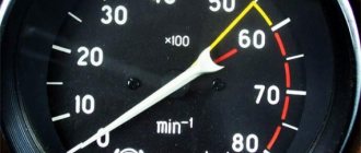
The tachometer in a car is used to indicate the number of revolutions of the engine crankshaft. Let's look at why the tachometer doesn't work and how to find and eliminate the cause of the breakdown. We will definitely dwell on the device and principle of operation, which will help to find out why the tachometer stopped working, the needle twitches or behaves inappropriately.
Poor contact on the connector
Driving on bad, bumpy roads leads to a violation of the reliability of fastening the contacts and plugs of the devices inside the panel. Low reliability of fastenings leads to loss of contact on the tachometer connector.
In the photo above you can see the white plug for connecting the wire block. The presence of oxides on the surface of the plug can interfere with the normal operation of the tachometer. Also, due to a poor fit of the plug, the sensor may act up and periodically display incorrect speed readings. On the surface of the board there are transistors, resistors, microcircuits, and board tracks. Failure of any of the listed elements can lead to failure of the device.
Classification by operating principle
- Mechanical or electromechanical tachometers with direct drive. The revolutions are transmitted to the dial indicator through a flexible shaft, which, through a worm gear, receives rotation directly from the crankshaft or one of the transmission shafts. The operating principle of the indicator is based on the phenomenon of eddy current induction. The operation and design of a magnetic tachometer are extremely similar to the operating principle of a car speedometer. In modern cars, a similar tachometer design is not used.
- Electric machine. A distinctive feature is the connection to a generator. It is used primarily on diesel engines, but for the purpose of unification, a device of this type can also be used on gasoline engines.
- Electronic. The signal can be taken either from the ignition system or directly from the computer. Installed on gasoline and diesel internal combustion engines.
Design and principle of operation
Main components of electric machine and electronic tachometers:
- measuring unit, or signal converter. It can be based on elements of analog circuitry or built using special microcircuits;
- display unit with analogue or digital display of the number of revolutions;
- auxiliary elements.
The operation of electronic tachometers is based on the conversion of individual signals or pulses captured from the computer, ignition system or generator into a signal “understandable” for the display unit.
Connection diagram
When looking for the reason why the tachometer does not work, it is first of all important to understand the connection diagram and the type of signal. There are 3 typical connection schemes:
- to a contactless ignition system (the tachometer wire is connected to the primary circuit of the ignition coil). The operating principle is based on measuring the frequency of voltage surges in the primary circuit of the ignition system. Calculating the ignition angle is impossible without focusing on the number of crankshaft revolutions, therefore the sparking frequency directly depends on the crankshaft rotation speed. On 4-cylinder internal combustion engines, a full revolution of the crankshaft corresponds to 2 voltage pulses in the primary circuit. Accordingly, the higher the crankshaft rotation speed, the greater the frequency of voltage surges;
- connection to the contact ignition system. The operating principle and connection diagram are similar to the BSZ, but the design of the measuring unit will differ depending on the voltage of the input circuit;
- connection to the engine ECU. The principle of operation is still based on recording voltage pulses in the primary circuit of the ignition system, but the signal to the tachometer comes from the engine control unit;
- connection to the generator (the tachometer signal contact is connected to terminal W of the generator). The rotation of the generator pulley is carried out by a belt drive from the crankshaft, so the rotation speed of the generator rotor will always be proportional to the crankshaft speed. The change in the number of revolutions of the crankshaft can be calculated by constantly measuring the amount of EMF generated on the winding. According to its principle of operation, an electric machine tachometer resembles a regular one class=”aligncenter” width=”448″ height=”412″[/img]
Device
The tachometer of the VAZ “fourteenth” model is very simple. Its basis is the car's ignition module. This device contains a Hall pulse chopper. Due to the rotation of this device, an electrical impulse is generated. For one revolution of the crankshaft, only 2 discharges are formed (for 1–3 and 2–4 pistons). These signals are transmitted to the on-board computer. The ECU calculates the speed and number of received pulses. Based on these data, the magnitude of the electrical signal and its duration are calculated, which will be transmitted to the tachometer receiving unit in the car. Also, an exactly identical signal, but with a higher frequency, comes to the ECU from the crankshaft sensor. The computer compares the number of pulses and transmits the result in the form of a pulse voltage to the tachometer itself, located on the dashboard of the car. Two completely different devices allow you to obtain the most accurate data on the number of revolutions of the power unit.
The system is quite simple, but breakdowns often occur in it. The following will describe in detail the symptoms of a tachometer malfunction.
General information about VAZ-2114 sensors
Sensors look like small mechanisms. However, their role in the operation of the entire vehicle system is simply colossal. They signal the remaining fuel in the gas tank, inform the driver of the coolant temperature, and determine the position of various engine elements in a certain operating mode. In order to know your car well and understand what could fail in a given situation, you need to know the entire list of mechanisms involved in the system.
We list all the sensors on the VAZ-2114 injector 8 valves, which are the most important:
- Crankshaft positions.
- TPDZ.
- Camshaft position sensor.
- DTOZH.
- Speed.
- Idle move.
- DMRV.
- Lambda probe.
These devices are in most cases located in the engine compartment. Almost all of them are installed at the factory during vehicle assembly. But the driver himself can install some sensors at any suitable time. It is also important to know how each of these devices works and what primary task it performs.
Fault repair
In fact, no one is repairing the speed sensor on these VAZ models, since it is much easier and faster to replace this entire unit - it costs around 400 rubles, which is not that expensive.
In order to begin the replacement process, it is recommended to drive the car into a pit and prepare screwdrivers, pliers and a set of wrenches. If there is no hole nearby, you first need to remove the terminals from the battery, then remove the air filter and intake pipe, and then remove the terminal from the DS itself (if the car uses a cable drive for the speedometer, you need to remove that too).
Next, use a rag to clean the work area of debris, oil or dust, and then proceed directly to the replacement:
- Remove the terminal block using the button that deactivates the spring retainer.
- Using a 21mm wrench, remove the speed sensor from its socket.
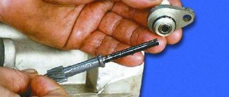
- Install the new device so that its rod precisely fits into the fixing sleeve to transmit rotation.
- Tighten the thread back with a 21mm wrench, without pinching it, so as not to damage the integrity of the plastic housing of the DS.
Replacing DS VAZ 2114
The result can be assessed immediately - if the sensor does not fit into the socket, it means that its rod has not moved into the bushing, so the procedure will have to be repeated until success is achieved. After this, you need to return the removed units to their place, connect the power and check the operation of the new sensor while the car is moving. Or, if the replacement was carried out in a pit and with a jack, you can evaluate the performance of the DS using the same multimeter and rotating the hung left wheel.
Crankshaft position sensor
You can often hear drivers with many years of experience calling this mechanism nothing other than a synchronization sensor. This name comes from the principle of operation of the device. The tasks of the DPKV are to synchronize the operation of the electronic unit and the gas distribution mechanism.
The VAZ-2114 is equipped with an inductive type DPKV. The cost of such a sensor is relatively small. If a vital controller for a car fails, most drivers prefer to immediately replace the device with a new one.
If the DPKV breaks down, further operation of the vehicle will become impossible. Without this mechanism, the fuel supply system will stop working, because the ECU will not receive information about when it is necessary to give a command to inject fuel into the cylinders. The location of the DPKV is in close proximity to the camshaft.
Electronics are responsible for fuel delivery in the VAZ-2114 car system. Without TPS, the control unit will not be able to determine the optimal time to supply gasoline. Deviations from the correct operation of the TPS lead to an increase in the amount of fuel consumed. The operation of many other car systems depends on the angle at which the remote control is located: cooling, fuel supply.
see also
The TPS is located near the idle speed sensor. In the “fourteenth” system, the work of these two devices is closely linked.
When the TPS breaks down, the car begins to twitch in a certain position of the damper, and instability of engine operation is also noted. All VAZ-2114 8 valve sensors are interconnected in their operation, so two different devices sometimes exhibit the same symptoms of malfunction. If symptoms of a breakdown occur, it is necessary to take a comprehensive approach to checking all controllers.
Examination
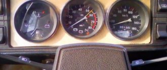
You need to start checking from the tachometer itself. For a quick test, you need to reset the odometer - hold down its button and turn on the ignition. If the tachometer and speedometer needles react to the supply of voltage, then both of these devices are working. If there is no reaction, then you will have to continue the search.
Fuse
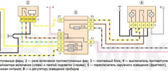
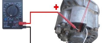
The tachometer does not have a direct connection through the fuse. It connects via a common dashboard control system. Fuse “F16” is responsible for protecting this system. In order to check it, you will need a tester in dial mode. Both tester probes must be connected to the contacts of the protective device. An audible alert will indicate integrity. If the fuse is blown, then it must be replaced with an analogue 15 ampere.
A short circuit and overvoltage in the electrical network does not go away without leaving a trace. It is necessary to measure the voltage at the fuse contacts. This requires:
- Switch the tester to DC voltage measurement mode.
- Connect the black test lead to ground or the car body.
- Connect the red test lead to the fuse contact.
The operating voltage should be 12 volts. It is also worth inspecting the safety block for melted housing, burnt fuse contacts or relay-breaker housings.
It is also worth carrying out a general inspection of the wires and cables of the vehicle's electrical circuit. A small penetration into the housing through the melted insulation also leads to failure of the fuse. The problem especially manifests itself after washing the car.
Ignition unit
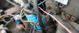
There is only one wire going from the ignition module to the tachometer. It is responsible for transmitting pulse signals. To check, you need to disconnect the connecting plug of this wire and check its contact. The presence of oxidation, dirt, and moisture is removed using a solvent. It is also worth checking this wire for integrity.
- Disconnect the second end of the wire from the ECU.
- Turn the multimeter into dialing mode.
- Connect both control probes of the tester to the ends of the wire.
- The presence of a buzzer will indicate the integrity of the element.
Next, you will need to check the block itself with a tester. To do this you need:
- Connect the red control probe of the tester to the tachometer connector.
- Connect the black test probe to ground.
- Start the power unit.
- Set the tester to DC voltage measurement mode.
The presence of a voltage from 0.6 to 12 volts will indicate the functionality of the mechanism. The voltage should rise and fall depending on the engine speed. If there is no voltage at all, then you should open the module and check the connection of the external plug and the internal contact of the impulse circuit.
On the “fourteenth” models, a magnetic type crankshaft position sensor is installed. To check it, you will need a tester in resistance measurement mode. There are only 2 wires suitable for it: power and return pulse. To check you need:
- Disconnect the power connector.
- Connect both tester probes to the connector contacts.
- If there are no readings from the tester, then you need to crank the engine with the starter until the sensor aligns with the missing tooth on the drive gear.
- The device will respond to this location by opening the contact, and the tester will show the resistance of the inductor.
Camshaft position sensor
This mechanism is located near the cylinder block. The main task is to transmit data to the ECU regarding the current operating cycle. Among specialists, the mechanism is called a Hall sensor. The operation of the device is based on the following principle: in accordance with the location of the crankshaft, the position of the gas distribution mechanism is determined. The data received by the sensor is reported to the electronic unit. Fuel is injected and the mixture is subsequently ignited.
Replacement
Practice has shown that the weakest unit in the speedometer system is the EMF. The plastic parts of this unit are very fragile and quickly wear out from friction. A faulty sensor will have to be completely replaced. To do this you need:
- Disconnect the “+” terminal from the battery.
- Remove the air purification filter and its pipe.
- Disconnect the current-carrying EMF connection.
- Using the “22” key, unscrew the part.
- Wash the sensor installation area thoroughly with solvent.
- Replace the rubber seal ring.
- Install a new EMF analogue.
- Reinstall previously dismantled parts.
Attention! Devices with gears have different numbers of teeth. If you install a part that differs from the original, a problem may arise in the accuracy of the speed readings.
Private situations
General signs do not always indicate specific breakdowns. There may be exceptions.
If individual devices refuse to work, it is quite possible that this is their personal problem. You'll have to parse the specific pointer. It may have a cracked gear that needs to be replaced.
Also, why doesn’t the instrument panel of the VAZ 2114 work? If the fuel gauge and tachometer are capricious (either they function, or they don’t react at all), the contacts and the mounting block are normal - you need to do a small check.
Reset is pressed and held, and the ignition is turned on at the same time. Raised arrows indicate the need for further searches. Lifeless - that microcracks have appeared in the shield itself. You will have to remove it and examine all soldering and traces under a magnifying glass. In principle, these are all the main options. If calling all the listed components and parts did not lead to the revival of the instrument panel, your case is individual, and you will have to determine the situation in the company of an experienced auto mechanic.
Analogs
Original speed sensors for injection VAZ-2114 are marked with article number 2111-3843010. This is a part in a plastic case, with a drive gear made of the same metal. The German analogue in a metal case is also suitable for this car model, but to install it you will have to redo the electrical contact socket.
Domestic EMFs are quite reliable. Their declared service life is up to 100–150 thousand kilometers. Rapid wear occurs due to dirt or damage to the housing itself during the repair of other components. You just need to monitor the condition of the part during operation.
What do you need to know?
Often, problems with the speedometer are related to electronic problems. Although a lot depends on the car. For example, if the speedometer needle of a VAZ-2107 twitches, then it is not necessarily a matter of wiring. The speedometer in this car is of a mechanical type, there are a minimum of wires. Therefore, very often the problem is a cable that has lost tension.
At the same time, the issue may be a faulty speed sensor. Many motorists check its performance first. After all, it’s much easier than disassembling the dashboard, fixing the problem and putting it back together. Let's look in more detail at the main malfunctions of speedometers on some car brands and consider methods for eliminating them.
Troubleshooting Methods
Usually, the functionality of control devices can be restored by replacing the speed sensor. As an example, consider the Hyundai Accent car. The speedometer needle twitches - we go to the store to buy a new speed sensor. With a high mileage of this brand of car, this is a completely typical problem that many motorists encounter. If the gearbox is mechanical, then the problem is most often solved by replacing the cable. Lubrication with WD-40 also helps, but this is more of a temporary solution, so the problem may return in the future.
A few important nuances
So we, in fact, figured out why the speedometer needle may twitch. As you can see, there can be a lot of reasons. But, when faced with such a problem, it is not at all necessary to immediately go to the service station. The malfunction can often be fixed on your own, of course, if you have the time and desire.
Oddly enough, with electronic systems in this case everything is much simpler. In most cases, it all ends with a banal replacement of the speed sensor or wiring. Another thing is that this sensor costs a lot of money for some cars. In this case, you can try to find a worthy analogue using online catalogs. But it is better to avoid openly Chinese products, which attract with their low cost. After all, such a sensor can please the owner of the car with correct operation for a short period of time, or even not work at all immediately after installation.
Atypical breakdowns
If the speedometer needle twitches (2109 is a VAZ or another model - it doesn’t matter, this type of breakdown is common to many cars), and the above method did not help, then there are several more options. One of them is wedging the arrow in a certain position. Therefore, when picking up speed, the instruments may show normally, but at some point there will be a jump. The problem can be solved by disassembling the dashboard and repairing the speedometer. It is likely that you will need to remove the arrow and lubricate it or replace it with a new one.
