Replacement of camshafts on the 16-valve VAZ-2112 engine occurs when they wear out and the support journals wear out. Most often this happens when the time for a major overhaul of the power unit or cylinder head passes. This is a rather complicated procedure, but you can really do it yourself.
The video below shows the installation of camshafts and split gears on a 16-valve engine of the VAZ family
The video material will tell you how to replace camshafts on a VAZ-2112 16 valves, and give some recommendations and advice.
Camshafts of engines 2112 and 21124 (16v) - removal and installation
The work is shown on engine 21124. For details of performing work on engine 2112, see the text.
1. We prepare the car for work (see “Preparing the car for maintenance and repair”).
2. Remove the camshaft pulleys (see “Camshaft pulleys - removal and installation”).
3. Remove the tension and guide rollers (see “Timing belt - replacement”).
10 mm socket wrench
unscrew the six bolts securing the rear timing belt cover and remove it.
5. Remove the cylinder head cover (see “Cylinder head cover for engines 2112 and 21124 (16V) - removal and installation”).
6. To avoid damage, remove the oil pressure sensor (see “Emergency oil pressure sensor in the engine - replacement”) or disconnect the wire tip from it.
8 mm socket wrench
Evenly, half a turn, unscrew the 20 bolts securing the camshaft bearing housing.
8. Remove the camshaft bearing housing.
On the 2112 engine, remove the camshaft bearing housing together with the guide pipes of the spark plugs (spark plug wells). We remove the pipes from the bearing housing.
9. We remove two plugs for technological holes from the seats in the cylinder head (near the rear ends of the camshafts).
10. Remove the camshafts of the intake and exhaust valves.
11. Remove the seals from the shafts.
12. Inspect the shafts. The journals and cams of the shaft should not show signs of heavy wear, scratches, cracks, or traces of metal envelopment.
1. Lubricate the bearing journals and shaft cams with clean engine oil.
2. Place the camshafts in the cylinder head. The shafts are not interchangeable and have different markings.
The exhaust valve shaft is marked 1006014.
The intake valve shaft is marked 1006015.
In addition, the intake valve shaft has an additional belt.
When repairing an engine, do not use sealant with a high content of silicone (silicon compounds), the vapors of which can get through the crankcase ventilation system into the cylinders and then into the exhaust tract. Use a sealant that specifically states on the packaging that it is safe for the oxygen concentration sensor.
Do not apply too much sealant to the mating surfaces of the bearing housing. When tightening the mounting bolts, the sealant squeezed into the internal cavities of the engine can clog the oil passages.
3. Apply a thin layer of Loctite sealant No. 574 or similar to the plane of the cylinder head and to the lower surface of the bearing housing around the holes of the spark plug wells according to the following scheme:
4. Install the camshafts into the cylinder head with the keyways facing up.
5. Install the bearing housing on the cylinder head and evenly tighten its mounting bolts until the bearing housing comes into contact with the cylinder head. We finally tighten the bearing housing mounting bolts in pairs, to a torque of 8.0-10.0 Nm (0.8-1.0 kgfm) in the following sequence (see photo).
Tightening sequence for camshaft support bolts
6. Press in the camshaft oil seals (see “Camshaft oil seals - replacement”).
7. On engine 2112
Apply clean engine oil to the rubber O-rings of the spark plug guide pipes (spark wells) and install the pipes into the head.
8. Further assembly is carried out in the reverse order of disassembly.
Source
Tuning a car VAZ 2110, 2111, 2112 Ten - Camshaft
Lada 2108 Raketa Logbook repair of the camshaft bed of the cylinder head of a VAZ 2112 or shesnar
Remove the camshaft gear pulley (see Composite camshaft drive pulley for an eight-valve engine).
To avoid losing the pulley key, remove it from the camshaft groove.
Using a 10mm wrench, unscrew the nut securing the rear timing belt cover.
Using a 10mm wrench, unscrew the two nuts securing the throttle cable bracket to the receiver...
...and remove the bracket.
Using a Phillips screwdriver, loosen the clamps securing the two crankcase ventilation outlet hoses and remove the hoses from the valve cover fittings.
Using a Phillips screwdriver, loosen the clamp securing the crankcase ventilation supply hose and remove the hose.
Using a 10mm wrench, unscrew the two nuts securing the valve cover.
Remove the valve cover.
Rubber sealing bushings are installed in the valve cover holes.
Remove the valve cover gasket.
Using a 10mm wrench, unscrew the two nuts securing the ends of the ground wires to the studs of the cylinder head plug and remove the wires from the studs.
Use a 10mm wrench to unscrew the two nuts...
...and one bolt securing the plug.
We remove the plug...
...and its O-ring.
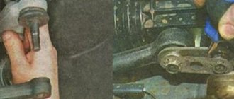
Using a “13” wrench, evenly in several steps (until the pressure of the valve springs is removed), unscrew the ten nuts securing the camshaft bearing housings.
Remove the front one from the studs...
...and the rear camshaft bearing housings.
Moving the rear timing belt cover slightly away from the cylinder head, remove the camshaft.
Remove the camshaft oil seal.
We install the tuning camshaft in the following sequence.
We clean the mating surfaces of the cylinder head and bearing housings from sealant and oil.
Lubricate the bearing journals and camshaft cams with engine oil. We place the shaft in the cylinder head supports so that the cams of the first cylinder are directed upward (the figure shows the position of the cams of the first cylinder when the camshaft is placed in the cylinder head supports).
On the surfaces of the cylinder head that interface with the bearing housings in the area of the outer supports, apply a thin layer of sealant (arrows).
We install the bearing housings and tighten the nuts securing them in two steps.
Pre-tighten the nuts in the sequence shown in the figure until the surfaces of the bearing housings touch the cylinder head.
In this case, it is necessary to ensure that the installation sleeves of the housings fit freely into their sockets. We finally tighten the nuts to a torque of 21.6 N.m (2.2 kgf.m) in the same sequence.
After tightening the nuts, carefully remove any remaining sealant.
After lubricating the working edge of the new oil seal with engine oil, press it into place with a suitable piece of pipe.
We install the camshaft timing belt and timing belt. (See Composite camshaft pulley for eight-valve engine).
Turn the crankshaft clockwise until the timing marks on the camshaft sprocket and the rear timing belt cover align.
Then we turn the crankshaft another 40-50° (2.5-3 teeth on the camshaft pulley).
In this position of the shafts, we use a set of feeler gauges to check the gaps at the first...
... and the third camshaft cam.
The clearance between the camshaft lobes and the washers should be 0.20 mm for the intake valves and 0.35 mm for the exhaust valves. The clearance tolerance for all jaws is ±0.05 mm.
If the gap differs from the norm, then install a device for adjusting the valves on the studs of the camshaft bearing housings.
We introduce the “fang” of the device between the cam and the pusher.
We rotate the pusher so that the slot in its upper part faces forward (along the direction of the car).
By pressing the lever of the device, we recess the pusher with the “fang”...
...and install a clamp between the edge of the pusher and the camshaft, which holds the pusher in the lower position.
Move the lever of the device to the upper position.
Using tweezers, pry the adjusting washer through the pusher slot and remove it.
If you do not have a device for adjusting the valves, you can use two screwdrivers.
Using a powerful screwdriver, leaning on the cam, press the pusher down. By inserting the edge of another screwdriver (with a blade at least 10 mm wide) between the edge of the pusher and the camshaft, we fix the pusher.
Use tweezers to remove the adjusting washer.
Installation and replacement of camshafts on a 16-valve VAZ-2112
Replacement of camshafts on the 16-valve VAZ-2112 engine occurs when they wear out and the support journals wear out. Most often this happens when the time for a major overhaul of the power unit or cylinder head passes. This is a rather complicated procedure, but you can really do it yourself.
The video below shows the installation of camshafts and split gears on a 16-valve engine of the VAZ family
The video material will tell you how to replace camshafts on a VAZ-2112 16 valves, and give some recommendations and advice.
Engine 2112 characteristics
Which is better Lada Priora or Lada Kalina
Years of production - (1997 - 2004) Cylinder block material - cast iron Power system - injector Type - in-line Number of cylinders - 4 Valves per cylinder - 4 Piston stroke - 71mm Cylinder diameter - 82mm Compression ratio - 10.5 Engine displacement 2112 - 1499 cm cube Engine power 2112 – 93 hp. /5600 rpm Torque - 128 Nm / 3700 rpm Fuel - AI95 Fuel consumption - city 8.8 l. | track 5.5 l. | mixed 7.2 l/100 km Oil consumption - 50 g/1000 km Weight of the VAZ 2112 engine - 127 kg Overall dimensions of the 2112 engine (LxWxH), mm - Oil for the VAZ 2112 engine: 5W-30 5W-40 10W-40 15W40 How much oil in engine 2112: 3.5 l. When replacing, pour 3.2 liters.
Resource: 1. According to the plant – 150 thousand km 2. In practice – 250 thousand km
TUNING Potential – 400+ hp. Without loss of resource - up to 120 hp.
The engine was installed on: VAZ 21103 VAZ 2111 VAZ 2112
Camshaft replacement process
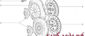
Camshafts with gears and fasteners
In order to install camshafts on the VAZ-2112 16 valves, they must first be dismantled. Like any spare part, they are installed in the reverse order from disassembly.
So, let's look at the step-by-step process of removing and installing the intake and exhaust camshaft.
Removing camshafts
- To begin with, as with any repair operations, it is necessary to remove the “minus terminal” from the battery.
- Remove the timing belt cover.
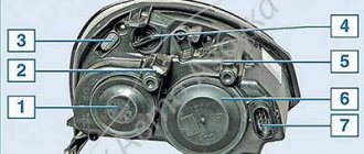
After unscrewing the mounting bolts indicated in the diagram, remove the timing cover
Unscrew the fastening nuts and remove the valve cover.
Disconnect the emergency oil pressure sensor
Scheme for dismantling and tightening the camshaft bearing housing bolts
You need to be careful with the camshaft plugs; if you install them incorrectly, oil will leak out. If you don’t notice it in time, you’ll shorten the engine’s lifespan or end up in need of a major overhaul.
Remove the two rear cylinder head plugs
We remove the camshafts from their seats
Remove the seals from the camshaft. If it does not come off, carefully cut it or pry it off with a screwdriver.
Installation of camshafts
Now that everything is removed, you can proceed to installing new camshafts on the car:
- Lubricate the cams and shaft support journals with engine oil.
Lubricate the camshaft journals and cams with engine oil.
The intake camshaft is shown on the left and the exhaust camshaft on the right.
How to apply sealant to the camshaft bearing housing cover
We press new oil seals onto the camshafts
Choice
Cylinder head camshafts for the VAZ-2112 are produced only by the manufacturer, so there is no need to look for analogues.
Original catalog numbers: inlet - 2112-1006015, outlet - 2112-1006014 . Each camshaft costs an average of about 3,000 rubles.
Nuances
When installing the bearing housing and cylinder head, do not apply sealant that contains silicone. This is due to the fact that the motor heats up, and accordingly the sealant heats up, which releases vapors that can get into the cylinders and further through the system . You should use a sealant whose instructions or packaging indicate that it is safe for the oxygen sensor.
When applying sealant to cavities, you should not apply a lot of it, because when tightening the bolts, it can get inside and this will lead to clogging of the oil channels, and therefore there will be no lubrication. The lack of lubricant will lead to increased wear of parts that will quickly fail.
Removing camshafts
To begin with, as with any repair operations, it is necessary to remove the “minus terminal” from the battery. Remove the timing belt cover. Now you need to remove the valve cover
Please note that the bolt tightening order must be followed during assembly. Disconnect the wires of the emergency oil pressure sensor, and then unscrew it. Using a socket wrench or 8mm socket, unscrew the 20 bolts securing the camshaft cover. We dismantle the camshaft bearing housing. Now, there is free access to two plugs that are located on the rear side of the cylinder head. We take them out. We take out the intake camshaft. We take out the exhaust camshaft. We press the seals out of the camshafts.
Installation and replacement of VAZ-2112 camshafts 16 valves: photo, video
Replacement of camshafts on the 16-valve VAZ-2112 engine occurs when they wear out and the support journals wear out. Most often this happens when the time for a major overhaul of the power unit or cylinder head passes. This is a rather complicated procedure, but you can really do it yourself. The video below shows the installation of camshafts and split gears on a 16-valve engine of the VAZ family
The video material will tell you how to replace camshafts on a VAZ-2112 16 valves, and give some recommendations and advice.
Camshaft replacement process
Camshafts with gears and fasteners
In order to install camshafts on the VAZ-2112 16 valves, they must first be dismantled. Like any spare part, they are installed in the reverse order from disassembly.
So, let's look at the step-by-step process of removing and installing the intake and exhaust camshaft.
Removing camshafts
After unscrewing the mounting bolts indicated in the diagram, remove the timing cover
Unscrew the fastening nuts and remove the valve cover.
Disconnect the emergency oil pressure sensor
Scheme for dismantling and tightening the camshaft bearing housing bolts
You need to be careful with the camshaft plugs; if you install them incorrectly, oil will leak out. If you don’t notice it in time, you’ll shorten the engine’s lifespan or end up in need of a major overhaul.
Remove the two rear cylinder head plugs
We remove the camshafts from their seats
Remove the seals from the camshaft. If it does not come off, carefully cut it or pry it off with a screwdriver.
Installation of camshafts
Now that everything is removed, you can proceed to installing new camshafts on the car:
Lubricate the camshaft journals and cams with engine oil.
The intake camshaft is shown on the left and the exhaust camshaft on the right.
How to apply sealant to the camshaft bearing housing cover
We press new oil seals onto the camshafts
Choice
Cylinder head camshafts for the VAZ-2112 are produced only by the manufacturer, so there is no need to look for analogues.
Original catalog numbers: inlet - 2112-1006015, outlet - 2112-1006014. Each camshaft costs an average of about 3,000 rubles.
Intake camshaft marking Exhaust camshaft marking
Nuances
When installing the bearing housing and cylinder head, do not apply sealant that contains silicone. This is due to the fact that the motor heats up, and accordingly the sealant heats up, which releases vapors that can get into the cylinders and further through the system. You should use a sealant whose instructions or packaging indicate that it is safe for the oxygen sensor.
When applying sealant to cavities, you should not apply a lot of it, because when tightening the bolts, it can get inside and this will lead to clogging of the oil channels, and therefore there will be no lubrication. The lack of lubricant will lead to increased wear of parts that will quickly fail.
conclusions
Replacing and installing camshafts on a 16-valve VAZ-2112 is not entirely easy, but it is quite possible. The main thing to ensure results is caution and following instructions. It is worth noting separately that the intake and exhaust camshafts are different and not interchangeable. On the intake there is an additional border for the phase sensor.
DPRV is a device for determining data on the position of camshafts.
The sensor performs monitoring functions. The electromagnetic field of the sensor working element changes potential depending on the distance from the control mark, which is located on the camshaft.
In a sensor, as in any electronic device, there can be malfunctions, both systemic (functional) and current ones, associated with a violation of the contact tightness.
- All assembly and disassembly work to replace the sensor is carried out with the battery disconnected. To do this, disconnect the terminal supplying voltage to the car body - with a minus sign.
- Disconnect the connector sockets.
- Unscrew the sensor retaining bolt.
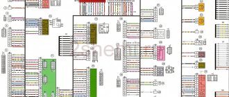
The sensor has three contacts, two of which (1st and 3rd) are intended, respectively, for connecting to ground and supplying power. A wire transmitting a signal is connected to terminal No. 2.
The sensor is installed in the reverse order.
How to change valves on VAZ 2110/2112 (instructions)
- Replacement must be done in a garage or closed box, where there is no wind and dust.
- Turn off the power to the car and disconnect the battery.
- Drain the engine lubricant and cooling fluid.
- We dismantle all the attachments: hoses, fuel supply, vacuum system, we get wide access to the parts that need to be worked with.
- Remove the cover from the main cylinder block (cylinder head).
- Remove the casing and belt.
- We unscrew the bolts that secure the cylinder head.
- After removing the cylinder head, we arm ourselves with a special puller (if it’s not available, ask your neighbors in the garage - it’s really more convenient to do the work with it). We remove the camshaft and disassemble the pushers from the cylinder head. We attach the removal device to the studs. And put a stand under the plate and take out the fastener crackers. We remove the plate along with the springs, as well as the stop plates located under the springs (before that, we also remove the valve seal).
- We remove worn out or damaged valves.
- The next step is to replace the guide bushings. It is better to use a special device (screw version) because when struck there is a chance of damaging not only the head, but also the landing site. We press out the guides and treat the new ones with lubricant.
- We press each bushing into its proper place. They have special locking rings installed on them, so we press them in until there is a characteristic click, which means that the part has found its place. Everything should happen without strong tension, which could damage the bushing. If things get tough, don't rush. When the guide is pressed in, it is adjusted to the required fit dimensions (we use a reamer 8 mm in diameter, install it in the guide and scroll).
- We blow air through the holes, removing any foreign debris. We take measurements of the guide holes. We insert new valves.
- If you notice that the valve does not fully adhere to the seat, you need to grind the valves. It is produced on special machines. However, it should be remembered that you should not grind the valve too much, and after grinding it must be thoroughly washed. An ideal grind is considered to be one in which the working visible strip is 1 millimeter.
- We assemble the cylinder head in the reverse order and connect the fuel and air supply and cooling systems. We connect the battery.
The valve guides must be pressed in with the retaining rings in place. The intake valve guides are shorter than the exhaust valve guides. On the inner surface of the bushings there are spiral grooves for lubrication of the valves: for the intake valve guide bushings - up to half the length of the hole, for the exhaust valve bushings - along the entire length of the hole.
Replacing camshafts on a VAZ 2114 with your own hands
Camshafts, like other mechanisms and components of a car, determine the quality of engine operation. This material will tell you how to determine the malfunction of the shafts, how to replace the camshafts on a VAZ 2112 16 valves, and what needs to be prepared for this.
The pulleys of the 16-valve VAZ 2112 must be replaced when they are worn out or have mechanical damage. In particular, we are talking about:
If some kind of extraneous knocking noise appears in the valves while the engine is running, it is usually caused by one of these damages. If you have recorded a reduced pressure of the engine fluid in the system, this may indicate an increase in the clearances in the bearings.
To do this, in order to eliminate this malfunction, it is necessary to grind and restore the pulley bearing journals. You should also enlarge the grooves through which the engine fluid flows. This is done so that the lubricating fluid, after the next grinding, lubricates the internal combustion engine elements. As for the necks, after grinding they should be polished with green GOI paste.
What is a throttle cable
By throttle cable, car enthusiasts understand the throttle cable, which plays an important role in the proper operation of the vehicle. The throttle valve is a structural part of the fuel intake system into an internal combustion engine. Its main function is to regulate the amount of air supplied to the engine for the air-fuel mixture. This damper is located between the air filter and the intake manifold. If the throttle valve opens, the pressure in the intake system is compared to atmospheric pressure. If it is in the closed position, then the pressure drops to vacuum. This action of the throttle valve is necessary to enhance the operation of the vehicle’s braking system and to ventilate the adsorber in the gasoline vapor recovery system.
Causes of malfunctions
The main cause of the malfunction is simple mechanical wear. Any oil seal is, by its nature, a consumable - after a certain period of time it begins to deteriorate, since it is made of an elastic material.
The malfunction may manifest itself in the form of changes in shape, swelling, scarring, rupture or chipping of the material from which the consumable is made. Another manifestation of a malfunction may be the cuff being completely squeezed out of the seat.
Other causes of problems with the camshaft oil seal are incorrect selection of consumables, manufacturing defects, or incorrect installation. In these cases, the oil seal also does not perform its functions and needs to be replaced.
How to distinguish the intake camshaft from the exhaust camshaft of a VAZ-2112: photo
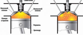
The camshafts of the 16-valve VAZ-2112 admit the working mixture and release exhaust gases. Unlike an 8-valve engine, where one camshaft serves for intake and exhaust, on a 16-valve engine there is a separate element for each phase. This improves not only engine performance, but also contributes to lower fuel consumption.
Photo of intake and exhaust camshafts
The intake and exhaust camshafts are indicated by arrows in the photo. The photo shows the engine with the valve cover removed.
Camshaft difference
The difference between the intake and exhaust camshafts is the presence of a groove for the phase sensor
16-valve 2008
16-valve 2008
The “smallest” of the 16-valve engines of the Volga Automobile Plant is the VAZ-11194 with a displacement of 1.4 liters. Two 1.6-liter models are also being produced - the already somewhat outdated VAZ-21124 and its more modern and powerful version, the VAZ-21126, which is gradually replacing its predecessor on the production line. Pay attention to the graph with engine characteristics: at crankshaft speeds close to maximum, the power and torque characteristics of the VAZ-11194 and VAZ-21124 are practically the same - and only at lower speeds is the “baby” inferior to its older brother. But engine 21126 is significantly - about 10% - more powerful and high-torque than the other two.
Let's get acquainted with their filling.
Cylinder blocks 21124 and 21126 are cast from cast iron. Compared to the previous one and a half liter analogue 2112, they are 2.3 mm higher (distance from the axis of the main bearings to the upper plane of the block). The cylinder diameter of engines 21124 and 21126 is the same - 82 mm. For selective engine assembly, 21124 blocks according to cylinder diameter are divided into five classes every 0.01 mm (A, B, C, D, E). Block 21126 has three classes separated by the same 0.01 mm (A, B, C). The cylinder class mark is located on the bottom plane of the block.
Other block sizes are identical. But there are differences in the requirements for processing the cylinder walls. Honing of cylinders 21124 is carried out according to the technology and requirements of AVTOVAZ, and 21126 - in accordance with the more stringent requirements of the Federal Mogul company, which have led to stricter requirements for the roughness of working surfaces. In order not to mix up the blocks, in addition to the markings made in the casting on the left wall of the block, the serial number is printed on the rear wall next to the fourth cylinder. Block 21124 is painted blue, and block 21126 is gray.
The cylinder block of the 11194 engine is similar in design to the 21126 block, but the cylinder diameter is smaller - 76.5 mm versus 82 mm. The processing of the cylinder walls is also in accordance with the requirements of Federal Mogul. Markings are in the same places, the block is painted blue. In addition, in block 11194 there are cooling jacket ducts between the cylinders, but 1.6 liter engines do not have them. For selective engine assembly, 11194 blocks are divided into three classes by cylinder diameter at 0.01 mm intervals (A, B, C).
The 21124 engine uses a 2110 connecting rod - steel, I-section, with a steel-bronze bushing in the upper head and axial fixation along the lower head (pictured above). The connecting rod cover is secured with two bolts pressed into the connecting rod. Based on the diameter of the bushing hole for the piston pin, connecting rods are divided into three classes every 0.004 mm. The hole class number is marked on the upper end of the connecting rod.
Engines 11194 and 21126 use connecting rod 11194, which is not interchangeable with connecting rod 2110. The new connecting rod, although it has grown from 121 mm to 133.5 mm, has become lighter - on average, it has “lost weight” from 683 to 412 g, which has seriously reduced inertial loads . Its axial fixation is ensured by the upper(!) head - along the piston. In this case, the steel part is in contact with the aluminum part, which reduces friction losses compared to the 21124 engine, where the steel connecting rod rubs against the cast iron surfaces of the crankshaft, and the friction speed is lower. The lower head, made using breaking technology, has become more elegant. Its cover is attached to the connecting rod with two bolts. Lengthening the connecting rod reduced the force of lateral pressure of the piston on the cylinder.
Engine VAZ-21127 features
The VAZ-21127 engine is one of the latest developments of the Volzhsky Automobile Plant. Today we will talk about its main differences from other VAZ engines, and also share our impressions of driving a car with this engine.
The VAZ-21127 engine is based on the “Prior” 16-valve VAZ-21126 engine, but has the following differences from it:
- maximum power increased to 106 hp. (VAZ-21126 has 98 hp)
- torque increased from 145 to 148 Nm
- Instead of a mass air flow sensor (MAF), an absolute pressure sensor (MAP) and an air temperature sensor (ATS) are installed
Characteristics of the VAZ - 21127 engine
Displacement - 1596 cc.
Maximum power - 78/5800 kW/rpm.
Maximum torque - 148/4000 Nm/rpm.
Maximum engine power - 106 hp.
Changes in the VAZ-21127 engine
The main change in the VAZ-21127 engine is the appearance of a controlled air intake system.
It is a new receiver in which controlled dampers are installed that regulate its volume depending on engine speed. At low speeds, air enters the engine through a long channel, at high speeds through a short channel, which should improve the elasticity of the engine. In essence, this is a conventional inertial supercharging system.
Impressions from the operation of the VAZ-21127 engine
For the first time, the VAZ-21127 engine began to be installed in the spring of 2013. At the moment it is installed on Kalina, Grant and Priora cars.
We tested this engine paired with a manual transmission on the new Lada Kalina, as well as with a robotic transmission on the Lada Priora.
What can you say about this engine? Indeed, the engine accelerates the car more readily. This is especially noticeable at low speeds, up to 2.5 thousand. Where a 98-horsepower engine accelerates rather sluggishly, a 106-horsepower engine allows you to maintain a good acceleration rate. But at high speeds, over 4 thousand, the differences are no longer so noticeable.
By the way, after abandoning the mass air flow sensor, the problem of floating speed at idle, which many owners of domestic cars suffered from, practically disappeared.
Tightening torque for VAZ-2112 camshaft bed 16 valves: order
Many motorists have heard that it is necessary to correctly tighten the threaded connections on the 16-valve VAZ-2112 engine, but they have never done it themselves. Thus, the tightening torque is determined by the manufacturer and is indicated in the service repair manuals.
Video about installing camshafts and split gears on a 16 valve engine
The video will tell you how to properly tighten the threaded connections on the camshaft beds
Torque and sequence of tightening the camshaft bed
Camshaft cover tightening sequence
Correct tightening of the camshaft bed, as well as other parts of the cylinder head, determines the normal functioning of all components and assemblies. So, in order to tighten threaded connections, a standard tightening pattern and a torque wrench are used.
Before installing the bolts in place, they must be washed thoroughly and lubricated with silicone grease.
In order to properly tighten the bolts, you need to know the sequence. It starts from the middle part and gradually moves directly to the edges. The detailed sequence can be seen in the photo below.
Tightening diagram for each camshaft bed bolt with numbering
Other cases in which dismantling of the cylinder head is required
Of course, it is not necessary to remove the cylinder head for every breakdown. This is only necessary if major repairs are needed. Such “major” cases include:
- Gasket wear.
- Formation of carbon deposits on parts.
- Valve deformation.
- Need to replace guide bushings.
- Failure of the camshaft, etc.
Of course, repairing it yourself or through a service in any case involves certain financial costs. To ensure smooth operation of the engine, regular diagnostics of the cylinder head are necessary. It is recommended to use high-quality fuel. In addition, try to prevent the car from overheating - because of this, the cylinder head may lead.
If some points remain unclear to you, then you can visually familiarize yourself with the process of replacing valves by watching the video:
HomeCarsVAZVAZ 2112
How to replace valves on a VAZ-2112 (21120) engine. One of the current methods is to remove the cylinder head
There is nothing special, but it is important to grind the valves in during the process. This applies to all VAZ engines
Cylinder head repair
We mark all hydraulic compensators with numbers using an ordinary clerical touch and put them away. An ordinary magnet will help you pull them out. We dry out the valves and remove the oil seals (valve seals), the valves into scrap metal, the oil seals into the trash. We clean all channels. We take the head for grinding, just in case. After washing it again with kerosene after sanding and blowing it with air, we begin to assemble it.
We arrange the freshly purchased valves in the sequence in which they will stand in the cylinder head and begin to grind in one by one. Lubricate the valve stem with clean oil and apply lapping paste to the edge.
We insert the valve into place and put a valve grinding tool on the valve stem. The stores sell a device for manual lapping, but since this is the twenty-first century, we are mechanizing the process. We take the old valve and cut off the rod from it, select a rubber tube for it of such a diameter that it fits tightly. The rod is in a reversible drill, one end of the tube is on it, the other is on the valve being ground in. At low speeds we begin to grind the valve, constantly change the direction of rotation and periodically press it to the seat or weaken the force. On average, the valve takes about twenty seconds. We take it out and wipe it. The valve is considered ground in if a uniform gray strip of at least 1.5 mm wide appears on the chamfer.
Procedure for installation and dismantling
The cylinder block is the basis for mounting the head, which is held on by 10 screws. Unscrewing is carried out with a special socket wrench - “ten”.
The photo shows the correct folding order:
- Top right corner.
- Bottom right corner.
- Top left corner.
- Bottom left corner.
- Top second from left.
- Top second from the right.
- Second bottom from the right.
- Second bottom from the left.
- Top in the middle.
- Bottom in the middle.
By strictly observing this sequence, you can avoid deformation of bolts and threads, as well as other unpleasant moments.
The design of the unit is quite complex, although at first glance it seems primitive.
The head is attached with bolts or studs to the block and closes the cylinders on top. The seating area of the upper element is very large, therefore the correct sequence of tightening the threaded connections with a specific force is very important. Previously, older car models had cast iron elements of this unit, which were easier to work with. Nowadays, softer, lighter and more ductile aluminum is predominantly used, when working with which it is very easy to damage a cylinder. Cast iron is also much more resistant to heat shrinkage and deformation, which does not yet allow us to completely abandon it.
The standard screw size in the model we are considering is 93 mm. If even one stretches even a couple of millimeters, it must be replaced immediately.
The installation sequence differs from the above order and is shown in the photo:
- Middle bottom.
- Upper lower.
- Bottom second from left.
- Bottom second from right.
- Top second from the right.
- Top second from left.
- Bottom corner left.
- Top corner left.
- Bottom corner right.
- Top corner right.
Tension torque standards:
- The force at the first stage is 20 N*m.
- Each element should be turned to the right by 90°.
- After waiting 20 minutes, you need to turn it another 90°.
The initial effort is small. But from the third stage the work becomes more difficult, so a lever is used. If you have any difficulties with the stretching process, watch the video tutorial in which everything is shown and explained in detail.
Installing a cylinder head under a turbine on an internal combustion engine is not much different from the option discussed above, but in case of inconsistencies or other problems, it is better to seek advice or help from qualified specialists.
Advantages of a sixteen-valve engine
We have already said that the internal combustion engines of the VAZ-2110 (2112) family discussed in the article are distinguished by greater power, lower fuel consumption, and also high technical characteristics, unlike the V8s. It's time to find out what design features make the VAZ 2112 16 valve engine such an attractive choice for motorists.
Let’s immediately make a reservation about exactly what “advantages” will be discussed in this section of the article:
- fuel economy;
- higher power;
- detonation resistance;
- advanced cooling system;
- simple tuning due to the separation of the intake and exhaust tracts.
It is the separation between the intake and exhaust tracts in the design of the VAZ-21120 and 21124 engines that makes it possible to achieve quite noticeable fuel savings. Thus, the supply of fuel and the intake of exhaust gases is carried out by a separate spaced valve system, due to which there is no unwanted mixing of fuel and combustion products. It is also obvious that this increases the efficiency of the engine and its power.
Advantages of a 16-valve engine
The VAZ 2112 with 16 engine valves has a number of advantages over cars of the same brand, but with fewer valves. Its main advantage is the ability to achieve maximum engine power, regardless of the type of the latter. (see picture).
For comparison:
- VAZ 2112 with a volume of 1500 cubic cm, has 77 horsepower.
- A VAZ 2112 of the same volume can have a power of up to 90 horsepower.
This difference is possible due to the fact that in the second case the filling of the cylinders with the warm-air mixture is much higher. In addition, the advantages of the 16-valve engine:
Better performance of the cooling system and, as a result, greater strength of the unit. Possibility of increasing engine knock resistance
This is especially important if low quality fuel is used. With 16 valves, the intake and exhaust tracts are located on opposite sides of the cylinder head, which facilitates their installation, repair, etc.
How to check the phase sensor
Before taking measurements and performing replacement work, it is worth visually inspecting the position sensor and checking the wires for integrity. If, as a result of the inspection, no malfunctions that could affect the operation of the device are identified, it is necessary to check the DPRV.
To find out whether the phase sensor is working or not, you will need some knowledge and ability to use a multimeter. Diagnostics can be carried out in several ways, so as an example, we will consider diagnostic methods for various DPRVs.
- Two-wire device. Operating procedure:
- start the internal combustion engine;
- switch the voltage measurement mode on the multimeter to the AC voltage position;
- Connect both wires from the electrical meter to two different terminals on the camshaft sensor. If the voltage fluctuates up to 5 V, then the part is serviceable; if there is no voltage, then replacement is necessary.
- Three-wire device. Operating procedure:
- start the internal combustion engine;
- switch the electrical measuring device to constant voltage mode;
- connect one contact of the multimeter to the black wire on the part, and the second to its power wire. If the voltage indicator is missing, then replacement is made. For a specific car model, the voltage value is indicated in the instruction manual.
The part is non-repairable, therefore, if it is found to be faulty, it is replaced with a new one.
When the throttle cable needs to be replaced
How to determine the moment when the VAZ-2110 throttle cable requires replacement? Experts recommend paying attention to the following points in the operation of this vehicle part:
- it is not possible to regulate the throttle valve drive;
- when pressing the accelerator pedal, the damper cannot open and close fully;
- the metal part of the cable began to “shag” (this can be seen visually when checking the internal parts of the car);
- When the throttle valve is operating, the gas cable constantly gets stuck.
If you find one of these problems in the operation of your vehicle, then you need to immediately buy a new throttle cable and replace it.
Let's move on to the cylinder block
We remove the pallet. Rotating the crankshaft as it is convenient for us, unscrew two bolts on each connecting rod cap. We use a TORX E10 head for this.
We take out the pistons along with the connecting rods. To do this, use the wooden handle of a hammer to press the connecting rod from below and lightly tap it to knock it up. We remove the old liners and buy new ones of the same size according to the markings on them. Here is another stone in AvtoVAZ’s garden, the owner has never climbed into the car from the interior or into the engine, but three pistons were of group “B” and one was “C”. It turns out that at the factory they re-sharpened one cylinder a little and simply put an enlarged piston there, no words. There are no options, we take group “C”, don’t sharpen the engine because of this. We will not touch the main liners either.
We buy a new piston group that does not bend the valves, connecting rods and connecting rod bearings.
Eliminating longitudinal play of the crankshaft
It was noticed on this motor. To eliminate it, replace the thrust half-rings. Standard and repair sizes are available. We take the first repair size, if they are too tight we sand them down a little. We unscrew the middle main bearing and gently push it with a screwdriver and move the half rings. The mark on it is in the form of three serifs, shown below.
When the half ring comes out a little, turn the crankshaft, it will push it out. There are two types of half rings: white at the front and yellow at the rear; the grooves on them should point towards the crankshaft cheeks.
We install them as we removed the new half rings; if they go in with great effort, you can grind them a little on a small abrasive stone, but not from the side of the grooves. Checking the play. We tighten the main bearing with a torque of 8 kgf*m.
Assembling the piston
There is an arrow stamped on the top of the piston; it should be directed towards the front of the engine. And there are marks on the connecting rod that should look the same way. Don't get confused!
We insert one retaining ring into the groove on the piston. We insert the connecting rod into the piston and, having lubricated the connecting rod and the piston pin with oil, insert it into place. Insert the second retaining ring. Although this operation seems simple, it will take some pains. We inspect the assembled structure; all retaining rings must be clearly in their grooves, otherwise a ring that has jumped out while the engine is running can cause a lot of trouble.
After assembly, you need to break off the connecting rod bearing cap, since the connecting rod is made in one piece. It's like that on our cars. First, unscrew the bolts. We insert the connecting rod into the cleats at the level of the mark shown in the figure with the black arrow and lightly clamp it, then break it off with a slight movement of the hand. The first time is very scary. We put the cover in place and tighten the bolts so as not to mix it up in the future.
Installation and dismantling procedure
The part called the cylinder head is attached to the cylinder block with 10 screws. They are unscrewed with a 10mm socket wrench. The procedure for dismantling the cylinder head is shown in the first photo.
Reversal sequence (1-10)
The standard screw length is 93 mm. If the screw has been pulled out to at least 95 mm, it is replaced with a new one (AvtoVAZ requirement).
During installation, a different scheme is used (photo 2). Each screw is lubricated with machine oil, otherwise the efforts will be reduced to nothing.
The order of tightening the head is indicated in this photo
Tightening torque for cylinder head cover bolts
For VAZ-2112, the cylinder head tightening torque is standardized:
- First pass – the force is 20 N*m;
- Each screw is turned 90 degrees to the right;
- Wait 20 minutes, then turn the screws another 90 degrees.
At first the effort is very small. But at “step 3” it will be difficult to cope with the work. Use the lever.
Why are guide bushings needed?
Before installing the cylinder head, perform the following steps: clean the threaded holes, as well as all holes for the bushings (photo 1). Each bushing is installed in place, and only then a gasket is placed on top.
Everything is ready to install the cylinder head
Metal parts adjacent to the gasket must be degreased. We looked at the cylinder head tightening diagram, but the cylinder head itself must be installed correctly:
- We place the cylinder head on the cylinder block;
- By moving the part in different directions, we ensure that the bushings fit into the recesses.
After “step 2” the screws can be tightened.
Sealant
No sealing compounds are used when installing the gasket! Solidol, CIATIM and other lubricants are not even needed. The main thing is that the metal must be degreased. And the cylinder head gasket must be new.
Hi all.
Last fall I noticed drops of oil in cylinder 4 and leaks around the entire perimeter of the valve cover.
I've been through the winter and it's time to fix the problem. I change everything together as usual. What we need:
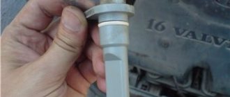
1) Anaerobic sealant "Locktite" 20 ml - 150r2) Camshaft oil seal BRT (cat. number 21080-1005034-00) 2 pcs - 240r per pair 3) Camshaft plugs 2 pieces (cat. number 21120-1003290-00) - 100r pair4) Crankcase ventilation pipes for engine 21126 (21126-1014240-00 (E-gas) - thin long, 21124-1014058-00 upper small, 21120-1014056-00 lower large - 3 pieces - 250r set5) Filter " Knecht" KL23of - 150r6) Carburetor cleaner - 150r7) Intake manifold and throttle gaskets - 150r set BRT8) Oil dipstick seal (cat number 21120-1009078-00) - 30r9) Torque wrench
I don’t see any point in describing the entire process of disassembling the valve cover. There are plenty of manuals, I’ll only focus on the moments that cause difficulties
Remove the decorative cover
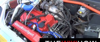
We remove all wires, ventilation hoses, and throttle. The receiver is secured with 2 bolts and 3 nuts. The nuts with the left bolt unscrew easily, you can crawl up. But there is a problem with the right bolt; the generator does not work.
I have a car with air conditioning, the pipes are in the way. There are two bolts near the gene; we remove them (the bolts are visible in the photo). When you remove the intake manifold, you need to bend the tubes, don’t be afraid to bend them, there are rubber inserts. Remove the generator belt, unscrew the top fastening and carefully move the gene towards the radiator with a pry bar.
Many motorists have heard that it is necessary to correctly tighten the threaded connections on the 16-valve VAZ-2112 engine, but they have never done it themselves. Thus, the tightening torque is determined by the manufacturer and is indicated in the service repair manuals.
Video about installing camshafts and split gears on a 16 valve engine